Skip to content
CRANE MANUFACTURER SINCE 2002
info@hnksglobal.com+86 188 3620 7779Project enquiry ↗
Henan Mine Crane Request a quote
KSX / Cross Travel Crane Systems

Track Switching Overhead Cranes

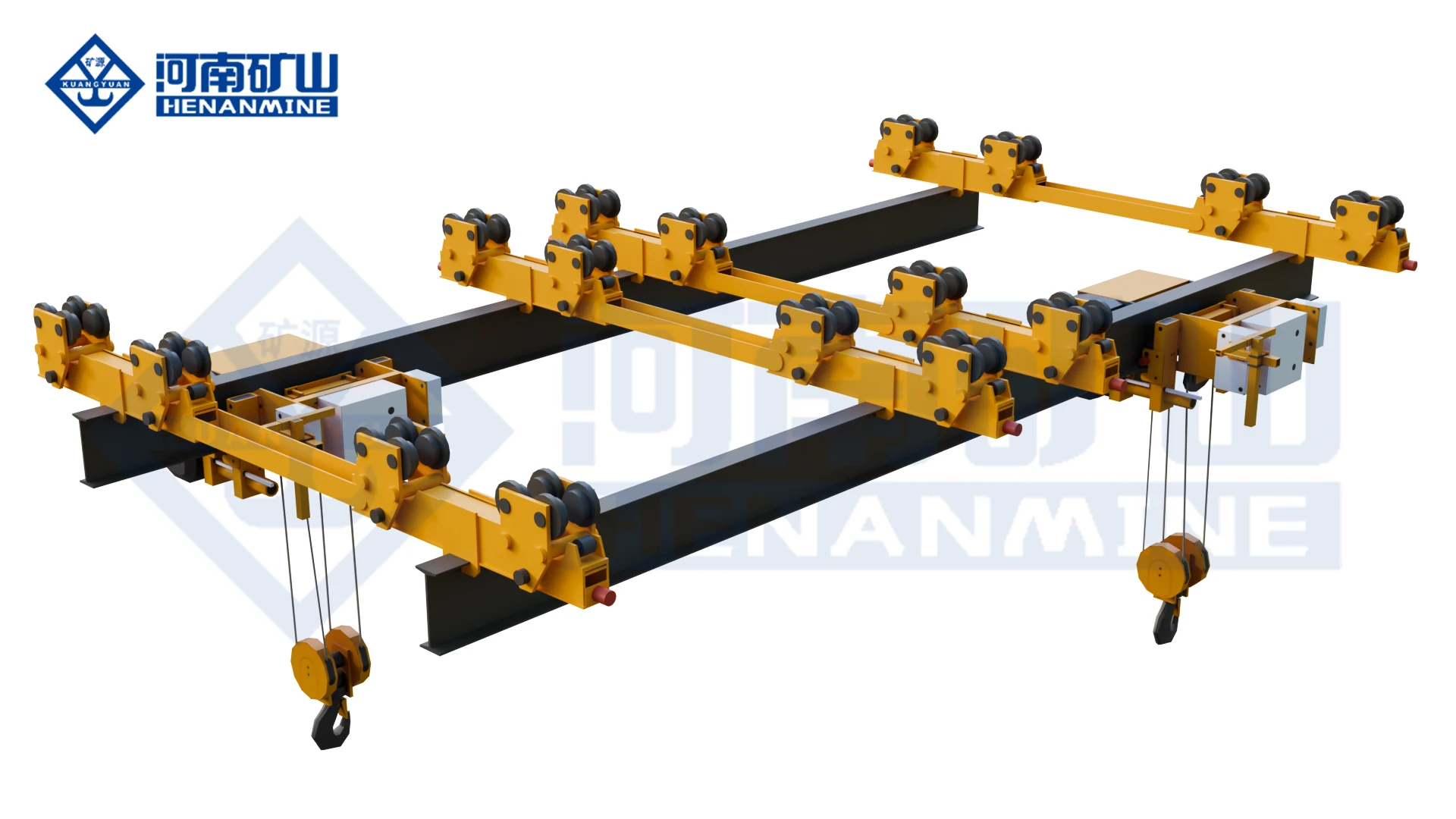
Track-switching overhead cranes for moving lifting equipment between separate high-level runways. The KSX / Cross Travel system is designed for power-plant coal-mill maintenance, multi-bay industrial workshops and equipment overhaul areas where one lifting system must cross from one runway or work zone to another.

KSX track switching cross travel overhead crane
1–32 tCurrent configurable Cross Travel crane range
3–30 mCurrent configurable span range
A5–A6Current medium-heavy maintenance duty
Multi-Track TransferHigh-level rail switching without ground rehandling
Product Family Structure

Complete Track-Switching Overhead Crane Range

Track-switching crane selection depends on the number of parallel tracks, track elevation, transfer direction, lifting capacity, clearance at the connection point and required switching frequency. The crane, rail-passing device and safety interlocks must be engineered as one transfer system.

Current Track-Switching Systems

Current Track-Switching Systems

Modern configurable track-switching cranes for multi-bay workshops and maintenance systems, with VFD motion, high-level rail transfer and engineered interlocks.

Cross Travel Overhead Crane
KSX / Cross Travel

Cross Travel Overhead Crane

A track-switching overhead crane for maintenance and material transfer between separate high-level runways. The crane can align with a rail-passing device, lock into position and transfer the hoisting unit or crane assembly between tracks, allowing one lifting system to serve multiple work areas without ground transfer equipment.

1–32 tA5–A63–30 m SpanHigh-Level Track Switching
Technical Specifications
Rated Capacity1–32 t or customized
Span3–30 m or customized
Lifting Height4–20 m or customized
Working ClassA5–A6
Hoisting Speed0.5–16 m/min, VFD adjustable
Trolley Travel Speed2–20 m/min
Crane Travel Speed5–30 m/min
Track ModeHigh-level multi-track switching
Protection LevelIP54
Power Supply220–690 V / 50–60 Hz
ControlWireless remote / pendant control
Typical ApplicationPower-plant coal mill maintenance, heavy-industry multi-bay workshops, cross-area equipment transfer
KSX configuration System

KSX configuration System

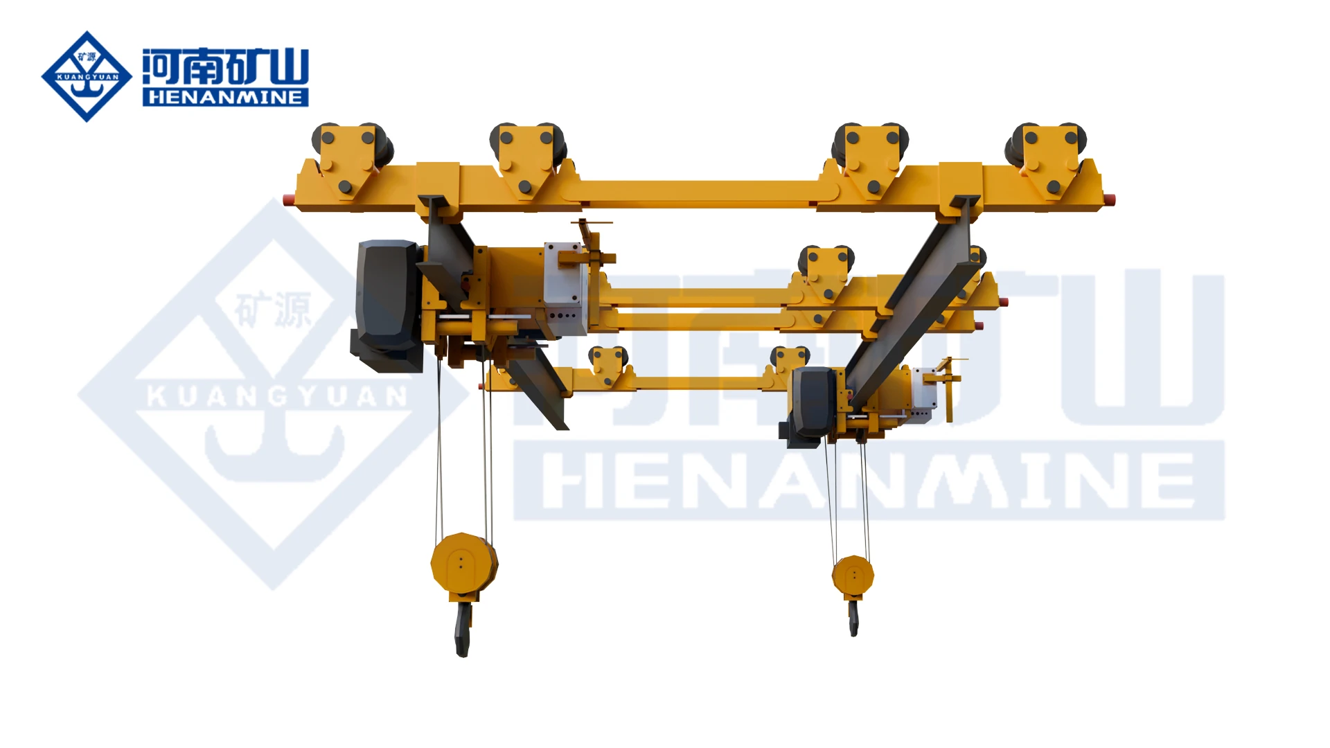
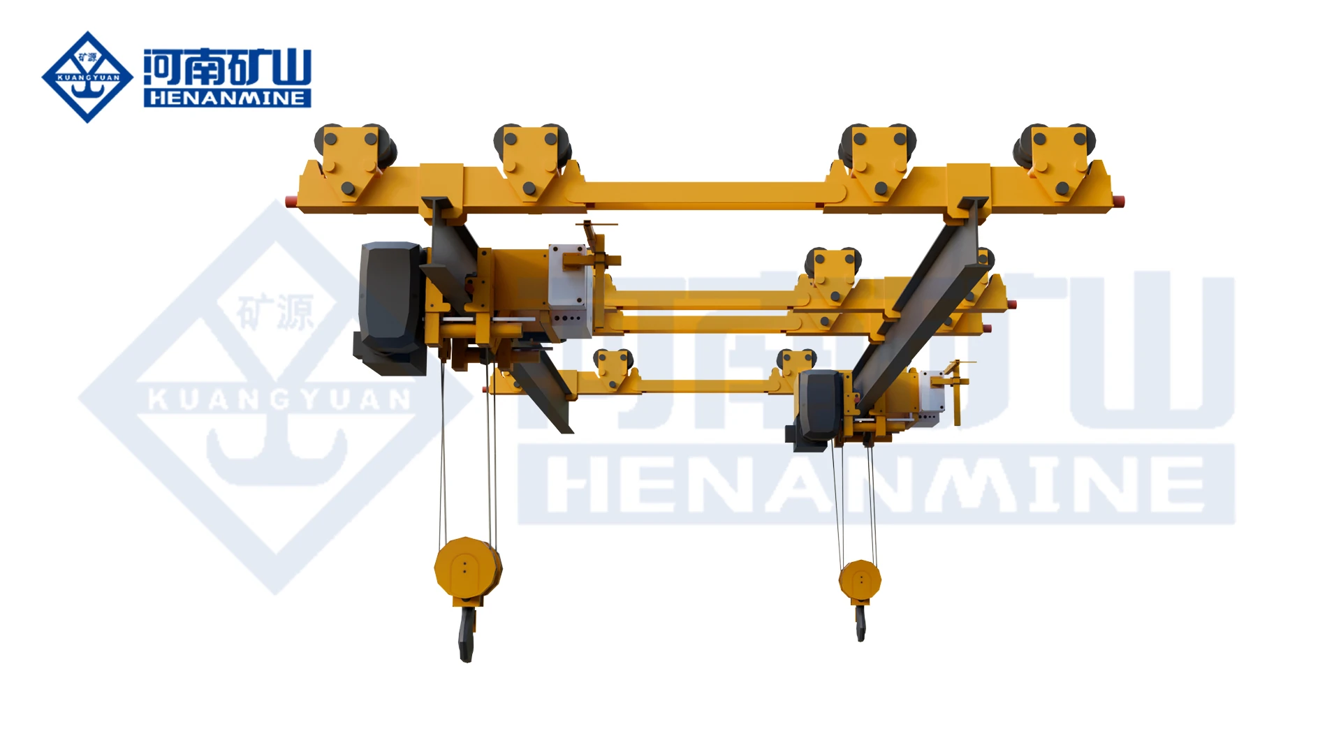
The KSX 12.5 t arrangement supports rail-passing crane travel in complex workshop layouts.

KSX 12.5 t Electric Double-Beam Underhung Rail-Passing Crane
KSX 12.5 t — Electric Main Travel

KSX 12.5 t Electric Double-Beam Underhung Rail-Passing Crane

The KSX system uses a 12.5 t electric-hoist trolley together with an electrically driven double-beam underhung rail-passing crane and a dedicated rail-passing device. The complete set was developed for generator-unit and coal-mill maintenance where lifting equipment must pass between adjacent tracks.

12.5 tA3Electric Main TravelRail-Passing Device
Technical Specifications
Rated Capacity12.5 t
Crane Span3.65 m
Vertical Dimension3.50 m
Working ClassA3
Mechanism ClassM3
Crane Travel Speed20 m/min
Travel MotorZDY21-4
Travel Motor Power4 × 0.8 kW
Wheel DiameterØ154 mm
Maximum Wheel Pressure20.83 / 20.29 kN
Ambient Temperature-25°C to +40°C
System Composition12.5 t hoist trolley + electric underhung rail-passing crane + rail-passing device
KSX 12.5 t Manual Double-Beam Underhung Rail-Passing Crane
KSX 12.5 t — Manual Main Travel

KSX 12.5 t Manual Double-Beam Underhung Rail-Passing Crane

A manual-main-travel configuration within the KSX rail-passing system. It uses the same 12.5 t hoist-trolley concept and rail-transfer arrangement but moves the main crane manually, providing a simpler configuration for selected maintenance layouts and lower-frequency cross-track operation.

12.5 tA3Manual Main TravelLow-Frequency Transfer
Technical Specifications
Rated Capacity12.5 t
Crane Span3.70 m
Vertical Dimension3.90 m
Working ClassA3
Mechanism ClassM3
Main TravelManual
Wheel DiameterØ154 mm
Maximum Wheel Pressure19.83 kN
Ambient Temperature-25°C to +40°C
System Composition12.5 t hoist trolley + manual underhung rail-passing crane + rail-passing device
Typical UseLower-frequency maintenance and cross-track transfer
Side-by-Side Selection

Track-Switching Crane Configuration Comparison

Compare the current configurable system with the KSX crane arrangement before defining rail geometry, locking method, transfer frequency, drive mode and maintenance duty.

ConfigurationCapacitySpanWorking ClassTrack / Travel ModePrimary Use
KSX / Cross Travel
Cross Travel Overhead Crane
1–32 t or customized3–30 m or customizedA5–A6High-level multi-track switchingHigh-Level Track Switching
KSX 12.5 t — Electric Main Travel
KSX 12.5 t Electric Double-Beam Underhung Rail-Passing Crane
12.5 t3.65 mA3Electric rail-passingRail-Passing Device
KSX 12.5 t — Manual Main Travel
KSX 12.5 t Manual Double-Beam Underhung Rail-Passing Crane
12.5 t3.70 mA3ManualLow-Frequency Transfer
Current 32/10 t Detailed Series

32/10 t Cross Travel Crane: Weight & Wheel Load by Span

The current 32/10 t crane series provides span-by-span crane weight and maximum wheel-load data for preliminary support-structure and track design.

Parameter7.5 m10.5 m13.5 m16.5 m19.5 m22.5 m25.5 m
32/10 t Total Weight (kg)12,53014,66016,36018,87021,65024,26027,060
32/10 t Max. Wheel Load (kN)167184196206215224233
32/10 t configuration Parameter Value
Lifting Height9 / 12 / 16 / 24 m
Lifting Speed3 (3/0.3) or 7 (7/0.7) m/min
Trolley Travel Speed20 m/min
Crane Travel Speed20 m/min
Recommended Rail43 kg/m
Total Motor Power20 kW
Rail Top to Crane TopH = 1900 mm
Hook Left / Right LimitationS1 = 1100 mm / S2 = 1600 mm
How Track Switching Works

Rail-Passing System Operating Sequence

1. Approach the Transfer Position

The crane or hoist moves to the designated rail-transfer point at controlled speed and enters the alignment zone.

2. Track Alignment

The moving rail section is aligned with the receiving track so wheel paths and structural interfaces are correctly matched.

3. Position Confirmation

Limit switches or position sensors confirm that the crane, transfer device and target runway are correctly aligned.

4. Mechanical Locking

The rail-passing device is mechanically locked before transfer to prevent track movement or separation under wheel load.

5. Cross-Track Transfer

The hoist trolley or rail-passing crane travels across the connection point onto the next track at controlled speed.

6. Unlock & Resume Operation

After the transfer is completed and the unit reaches the safe zone, the switching device is released for the next operating cycle.

Core Transfer Equipment

Rail-Passing Device & Crane System

KSX rail passing device and cross travel crane
Integrated Track-Switching System

Crane, Hoist Trolley and Rail-Passing Device Operate as One System

The KSX concept is not only a crane. The arrangement combines a hoist trolley, electric or manual underhung rail-passing crane and a dedicated rail-transfer device. Modern systems add VFD travel, position detection, mechanical locking and control interlocks so the crane cannot cross until the transfer tracks are correctly aligned and secured.

Core ComponentsHoist trolley + rail-passing crane + track switching device
Track ArrangementMultiple parallel or connected high-level tracks
Switching RequirementAccurate rail alignment before wheel transfer
LockingMechanical track locking with electrical status confirmation
ControlPendant / wireless remote / PLC interlocked control
Primary BenefitCross-area maintenance or handling without secondary ground transfer
Safety Interlocks

Critical Track-Switching Safety Functions

Rail Alignment Detection

Position sensors confirm that both track sections are aligned before the transfer movement is enabled.

Mechanical Track Locking

The transfer track is positively locked before wheel load crosses the joint, reducing derailment and separation risk.

Transfer-Speed Limitation

Low-speed or VFD-controlled travel through the switching zone reduces impact at the rail interface and improves positioning accuracy.

Travel Limit Protection

Limit switches prevent the crane or trolley from entering an unaligned or unavailable transfer path.

Overload & Emergency Stop

Overload protection and emergency stop functions remain active during normal lifting and the rail-passing sequence.

Control Interlock

Transfer, locking and travel commands are logically interlocked so conflicting operations cannot be executed simultaneously.

Application Selection

Where Track-Switching Overhead Cranes Are Used

Power Plant Coal-Mill Maintenance

One lifting system can move between maintenance tracks for mill components, motors, reducers and other equipment without repeated rigging or ground transfer.

Multi-Bay Heavy-Industry Workshop

Track switching connects separate production bays so large parts and maintenance equipment can move across workshop zones.

Large Equipment Overhaul

Compact underhung layouts provide lifting access above equipment where floor space is occupied by machinery and maintenance platforms.

Steel-Structure Fabrication

Cross-track movement can connect cutting, welding, assembly and storage zones without adding independent cranes to every bay.

Wind / Hydropower Components

Large components can be transferred across production, inspection and storage areas in multi-span plants.

Existing Plant Retrofit

Track-switching systems can solve cross-bay handling bottlenecks where adding ground routes or new runway columns is difficult.

Engineering RFQ

Request a Track-Switching Overhead Crane Proposal

Provide the rated load, number of tracks, track center distances, rail elevation, transfer direction, lifting height and switching frequency. Existing-plant projects should include roof/runway drawings and clear dimensions around every rail-transfer point.