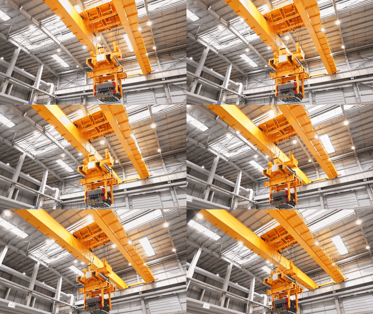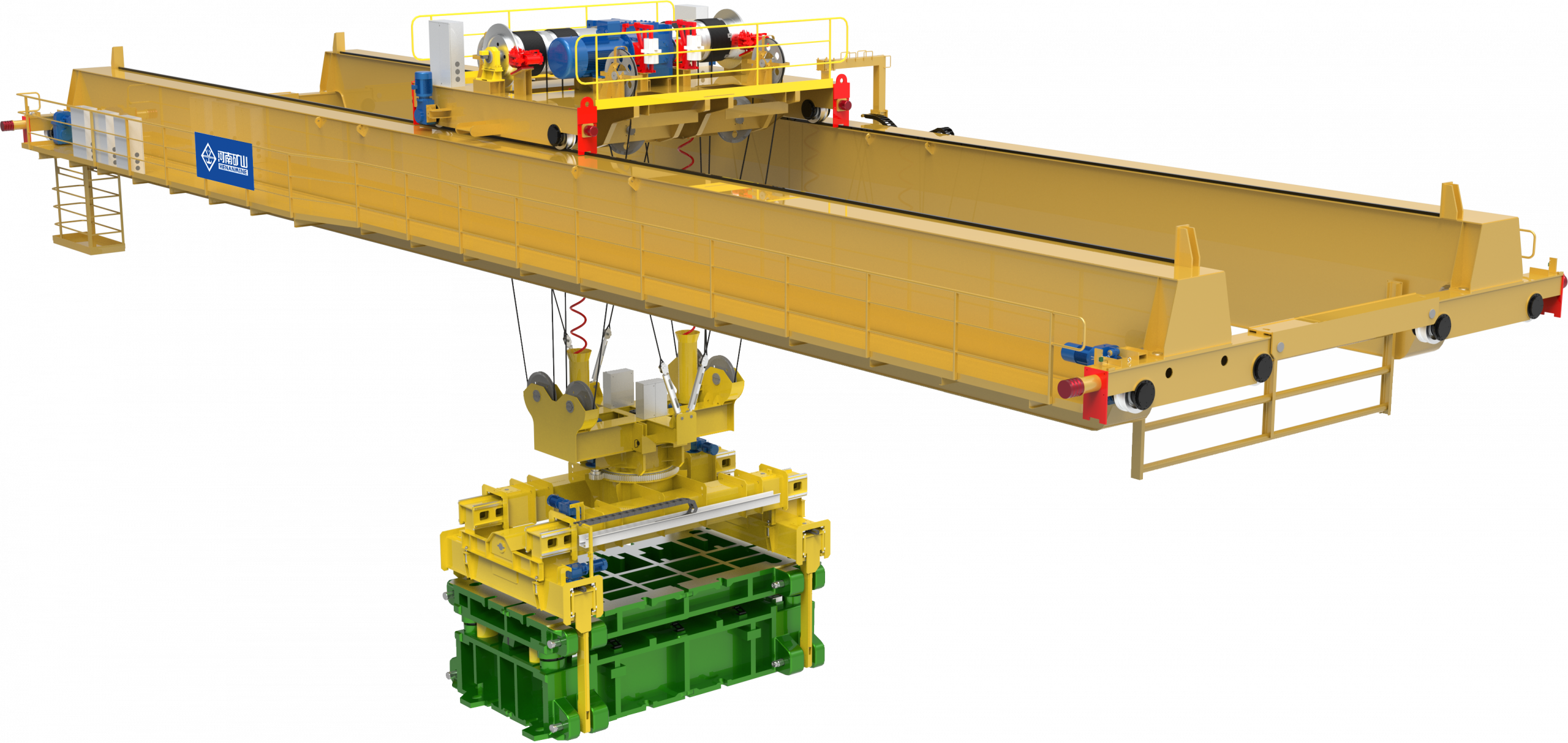
| Application | Automotive stamping die transfer |
| Attachment motion | X/Y extension and Z rotation |
| Integrated functions | Positioning, WCS management and anti-sway |
| Area protection | Laser anti-collision and light curtains |
Fit the lifting tool to the die
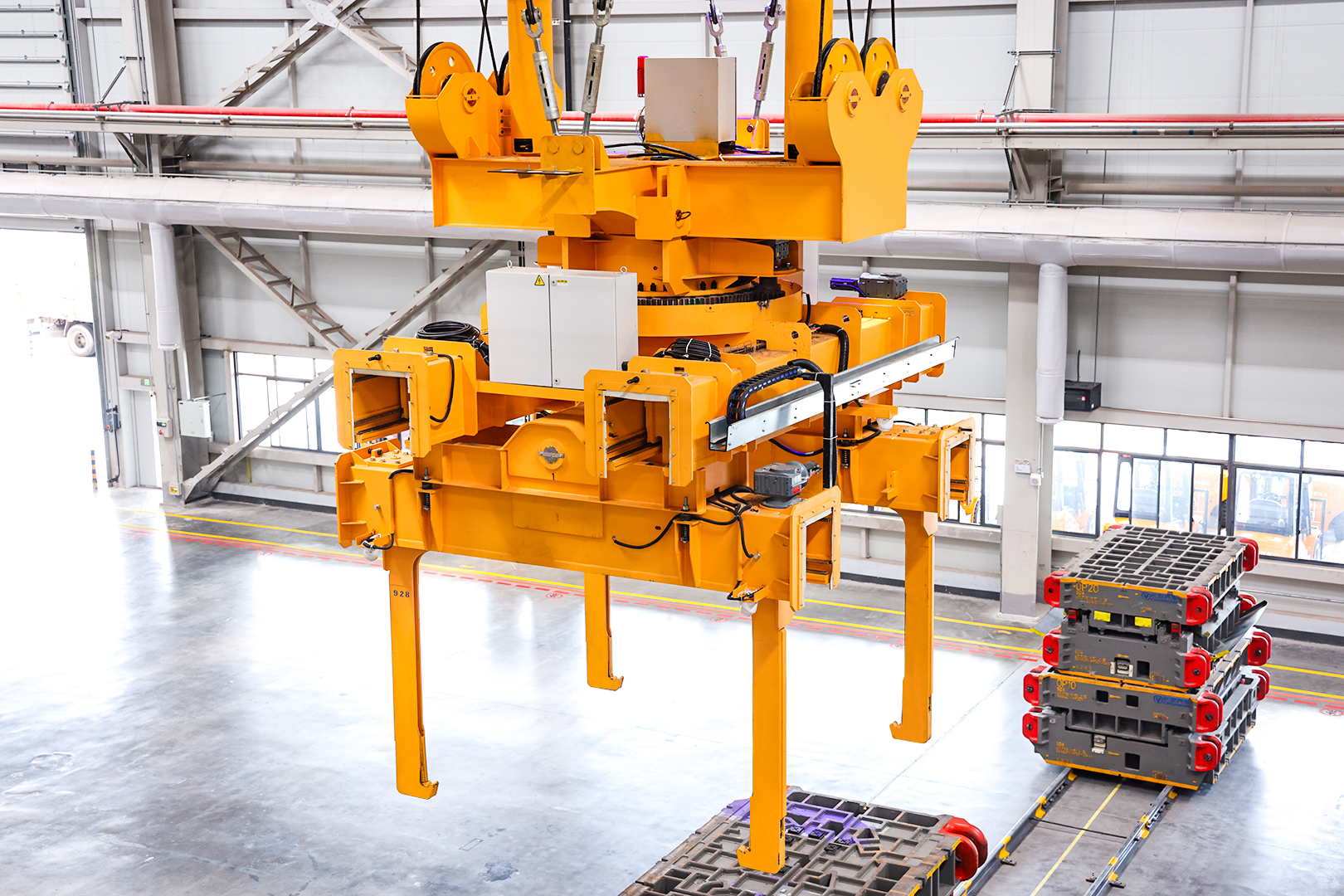
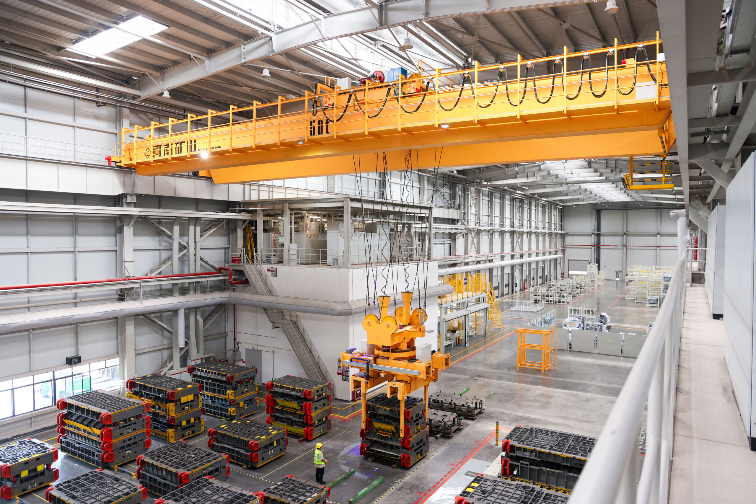
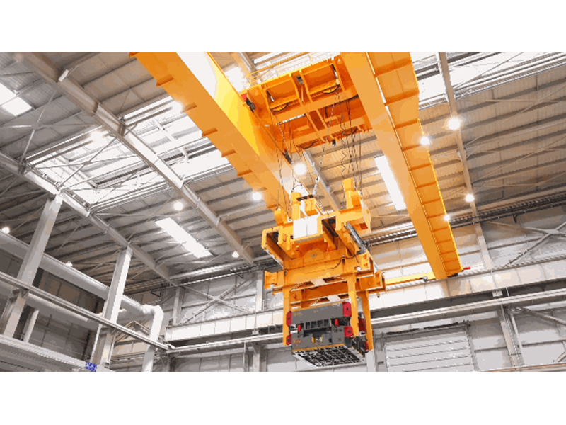
The dedicated attachment can extend along the X and Y axes and rotate along the Z axis. Combined with crane motion, it supports six-axis movement to accommodate different die specifications and transfer paths.
For a stamping-workshop enquiry, die dimensions, mass, lifting interfaces and required orientation determine the attachment arrangement. The transfer route must also account for presses, storage positions and the clearances needed during die placement.
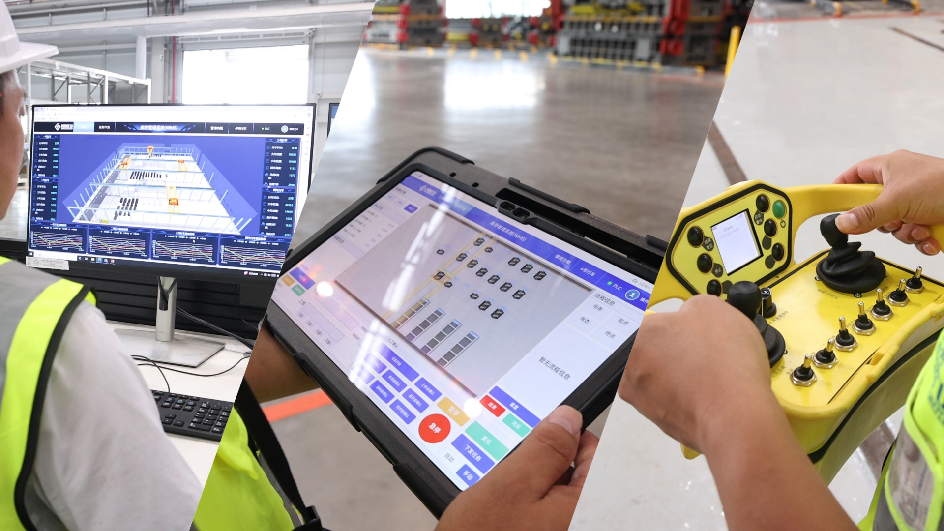
Coordinate positioning and workshop control
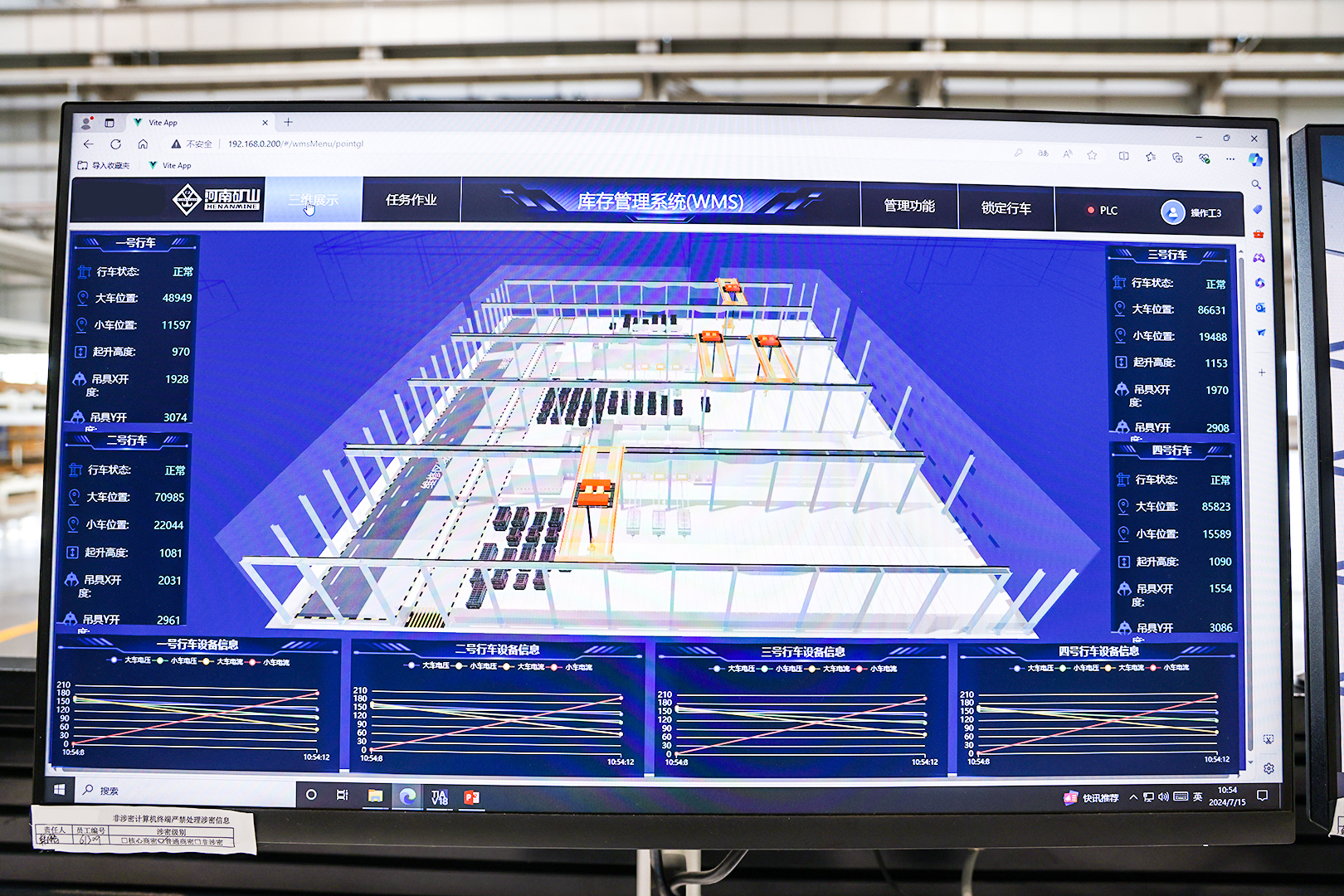
The cranes combine anti-sway functions with servo-controlled attachment positioning. The system includes automatic positioning and WCS management, allowing handling tasks to be coordinated within the workshop.
The control arrangement offers control-room, mobile and radio-control modes. A purchasing specification should define the duties of each mode and how control is transferred during normal operation, setup and recovery.
Define the protected operating area
Laser anti-collision functions, light-curtain area protection, video monitoring and three-dimensional visual/digital-twin functions form part of the arrangement. These features should be related to the actual transfer routes and staff-access points.
Agree demonstrations for position accuracy with a representative die, including the load condition and measurement point. Also review access response, obstacle detection and recovery from an interrupted movement as individual acceptance tasks.
Prepare a die-transfer brief
Send die drawings, the workshop layout, press interfaces and the handling sequence. Identify the required storage positions, software connections and changeover tasks so the crane and attachment can be reviewed as one handling system.
Photographs from this update