
Wall-Travelling Jib Cranes
Reach several lifting points along one workshop bay while keeping the floor route open. The jib carriage travels on a wall-supported runway; its arm and hoist then cover each workstation within a defined hook envelope.
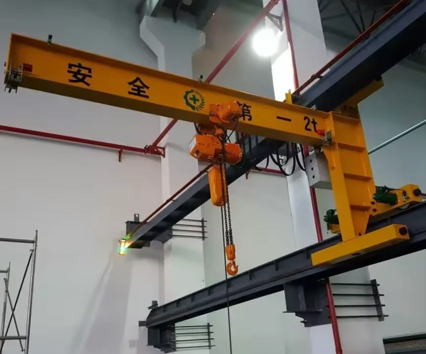
One rail route. Several lifting stations.
A fixed wall-mounted jib serves one pivot point. This arrangement moves the pivot along a runway so the same crane can reach successive work areas. It is suitable only where the existing structure can accept the running rails and travelling, lifted-load reactions.
Take material from a shared feed point and deliver it to machines arranged along the same wall-side bay.
Position components at several fixtures while keeping the floor free for material carts and operators.
Use the rail travel to bring the hoist beside equipment, then use the jib reach for local pick-up and set-down.
Specify the load, arm and runway as one system.
Capacity alone cannot define a wall-travelling jib. The arm, hoist, carriage, rails and building support must be checked together for the actual operating cycle. Reference options below are configuration choices; the selected values and their pairing belong on the approved drawing.
| Selection item | Available planning reference | Confirm in the final offer |
|---|---|---|
| Rated load | 0.5, 1, 2, 3 or 5 t reference options | Complete suspended load, including rigging and lifting attachments. |
| Arm reach | 5 or 6 m listed options | Usable inner and outer hook positions at each workstation. |
| Hook lift | 6 or 9 m listed options | Mounting level, highest load position and headroom. |
| Slew envelope | Up to 180° in the referenced layout | Travel-side clearance, allowable swing sectors and end limits. |
| Duty | A3 listed arrangement | Lift frequency, near-rated lifts and daily shifts. |
| Rail travel | Engineered to the workstations | Travel length, end stops, rail alignment and power-feed route. |
| Power | Three-phase AC arrangement | Site voltage, frequency, phases and protection requirements. |
| Building interface | Project-calculated reactions | Vertical and lateral loads, overturning moments, fixing and rail details. |
Draw the complete hook path before sizing the rail.
The hook has two movements: the travelling carriage moves along the wall and the hoist reaches out along the jib arm. Trolley end positions, hoist headroom, slew stops and the load dimensions reduce the usable area. The building must carry loads in every position along the route.
Mark the stationsShow each pickup and set-down point on a bay plan, with load height and access routes.
Define both travel and reachGive the first and last carriage positions plus the nearest and farthest hook positions from the wall.
Check interferenceShow doors, services, columns, adjacent cranes, roof members and every excluded swing zone.
Verify the structureProvide wall and column drawings so the calculated rail reactions and fixing layout can be approved.
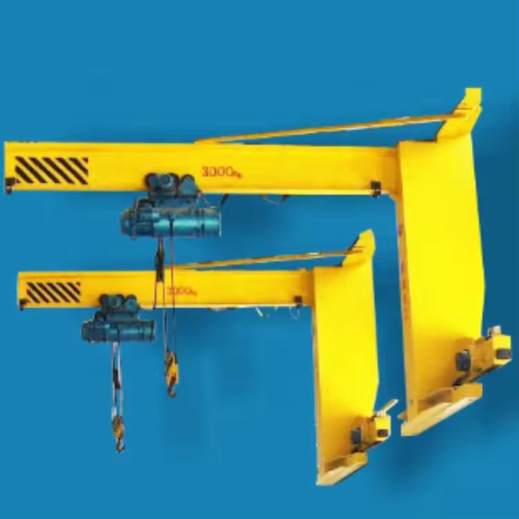
Use rail travel when one fixed pivot cannot do the job.
Sequential fabrication
Bring plate, frames or parts to several fixtures while leaving the aisle clear of a mobile lifting machine.
Long assembly stations
Move the hoist along the rail to the current build position, then reach into the station with the arm.
Wall-side maintenance
Serve motors, tooling or removable units at multiple positions on the same service route.
Need coverage across the full bay? Compare a single-girder overhead crane against the same lifting route.
Get a quote for the whole moving system.
Ask for one coordinated offer covering the jib, hoist, travelling carriage, rails, electrification, safety devices, structural interface and site work. A price for only the crane arm will not describe an installable system.
List the rated load, arm reach, hoist, trolley, carriage travel drive, control method, brakes, limits and overload protection.
Include rail length and section, fixing spacing, end stops, cable system and loads transferred into the building.
State who supplies steelwork, fixings, access equipment, electrical feed, installation, commissioning, load testing and operator training.
Resolve the rail route before ordering.
These answers determine usable coverage, building work and total installed cost.
How is this different from a fixed wall-mounted jib?
A fixed jib rotates around one wall support. A wall-travelling jib adds a carriage that moves along a wall-supported runway, allowing one crane to serve several stations along the bay.
Will the hook reach all stations along the rail?
Only if the approved plan shows the real carriage travel and the usable inner and outer hook positions. End stops, trolley limits, load dimensions and building obstructions all reduce the effective area.
Can an existing workshop wall carry the rails?
That requires an engineering check. Send wall, column and connection drawings; the crane supplier should provide calculated rail reactions for the selected load and arm so the building engineer can approve the support.
Which capacity, certification and delivery time apply?
The listed capacity options are not interchangeable with every reach and lift height. The final technical offer should pair the selected values, identify required destination documents and state the delivery and warranty terms after drawing approval.
Send the bay plan and lifting sequence.
Mark every station, complete suspended load, required hook positions, wall and rail support, operating cycle, power supply and destination. We can then define the crane, runway reactions, documentation and site scope in one comparable offer.
Send your wall-travelling jib enquiry ↗- Maximum complete suspended load
- First and last workstations along the bay
- Nearest and farthest hook positions
- Wall, column and rail support drawings
- Roof, doors and obstacle clearances
- Lift frequency, power, destination and site scope