
Check the complete working rope range
Specify the load at the least favourable drum layer and account for reeving losses and installation geometry.
- First and last working layer
- Per-line load and reeving
- Starting and holding force
Move and position heavy equipment with a planned, controlled rope line. JM series models pair their catalogue rated load with a particular speed, rope capacity and rope diameter. The final winch is selected for the working drum layer, braking requirement, mounting base and site duty—not by nominal tonnage alone.
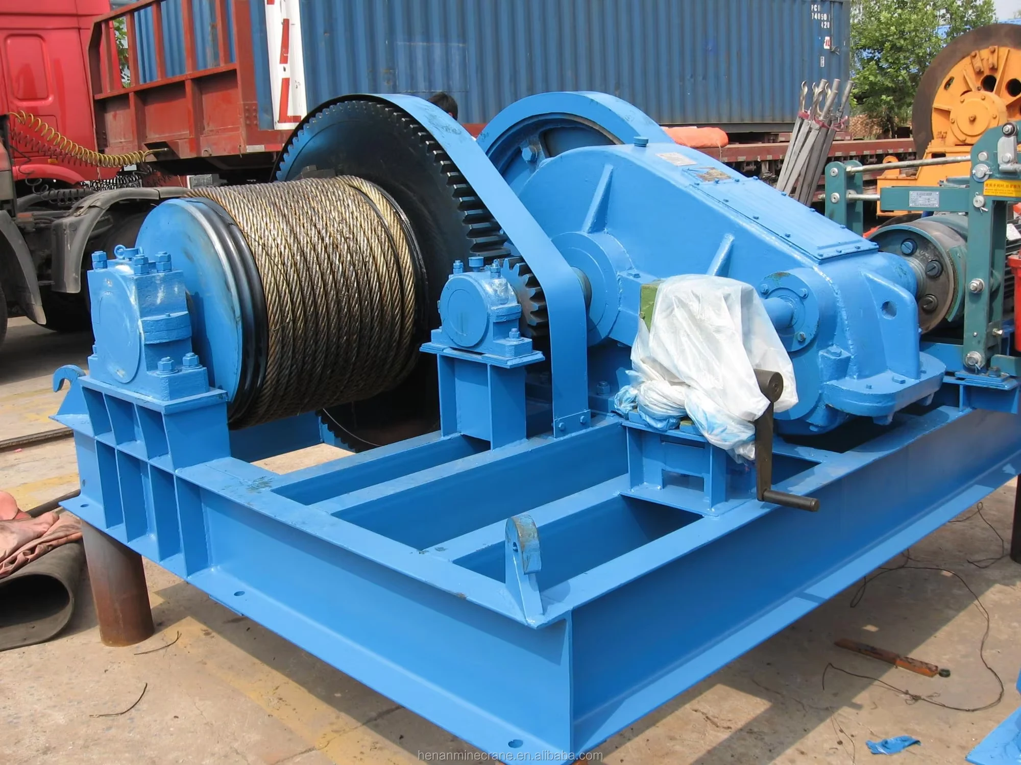
Send the required line pull at the working drum layer, usable travel, target speed, rope path, holding requirement and an anchor or foundation sketch. State pulling or suspended lifting clearly.
Model, minimum order and supplied equipment are confirmed in the written quotation.
Confirm rope route, working-layer pull, drum, brake, controls and foundation as one arrangement.
Agree inspection, documents, packing, schedule, installation support and warranty before the order.
Compare each model's listed load, speed, rope storage and diameter as one combination. Variants of the same nominal load have different speeds and capacities; select a complete configuration that fits the duty.
Compare the load path, rope movement and selected arrangement →
| Model | Listed rated load | Rated line speed | Rope capacity | Rope diameter |
|---|---|---|---|---|
| JM1 | 10 kN | 15 m/min | 100 m | Ø9.3 mm |
| JM1.6 | 16 kN | 16 m/min | 150 m | Ø12.5 mm |
| JM2 | 20 kN | 16 m/min | 150 m | Ø13 mm |
| JM3.2 | 32 kN | 9.5 m/min | 150 m | Ø15.5 mm |
| JM3.2B | 32 kN | 12 m/min | 195 m | Ø15.5 mm |
| JM5 | 50 kN | 10 m/min | 270 m | Ø21.5 mm |
| JM5B | 50 kN | 9.5 m/min | 200 m | Ø21.5 mm |
| JM5C | 50 kN | 9.5 m/min | 250 m | Ø21.5 mm |
| JM5D | 50 kN | 15 m/min | 250 m | Ø21.5 mm |
| JM5E | 50 kN | 20 m/min | 250 m | Ø21.5 mm |
| JM6 | 60 kN | 9.5 m/min | 270 m | Ø24 mm |
| JM8 | 80 kN | 8 m/min | 250 m | Ø26 mm |
| JM8B | 80 kN | 9.5 m/min | 350 m | Ø26 mm |
| JM10 | 100 kN | 8 m/min | 170 m | Ø30 mm |
| JM10B | 100 kN | 9.5 m/min | 250 m | Ø30 mm |
| JM12.5 | 125 kN | 8 m/min | 300 m | Ø34 mm |
| JM13.5 | 135 kN | 0-5 m/min | 290 m | Ø28 mm |
| JM16 | 160 kN | 10 m/min | 500 m | Ø37 mm |
| JM20 | 200 kN | 10 m/min | 600 m | Ø43 mm |
| JM25 | 250 kN | 9 m/min | 700 m | Ø48 mm |
| JM32 | 320 kN | 9 m/min | 700 m | Ø56 mm |
| JM50 | 500 kN | 9 m/min | 800 m | Ø65 mm |
Model rows are paired reference specifications. Confirm first- and last-working-layer pull, usable rope travel, brake, motor supply and intended pulling or lifting duty on the selected unit’s technical schedule.
Start with the required pull at the least favourable drum layer, not the maximum catalogue figure alone. Confirm usable rope travel, brake holding duty, anchorage and the actual speed needed near the final position.
Review selection options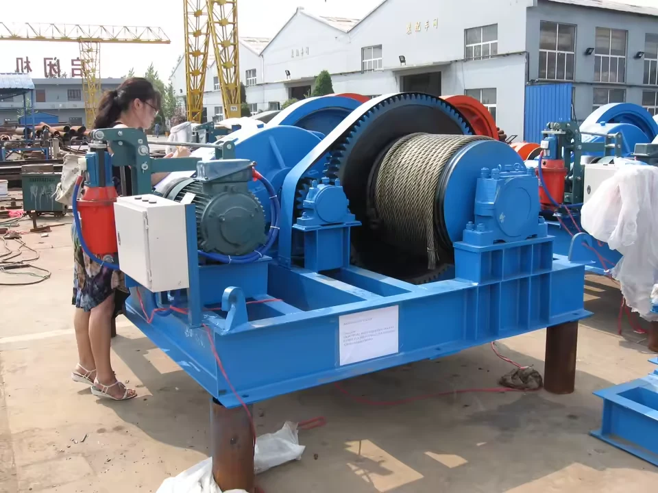
Move large equipment toward an installation point at a defined speed. State the total resistance, rope route, stopping tolerance and how the load will be secured when motion stops.
Pull or position a component along a surveyed route. Provide a rigging drawing showing each sheave, the anchorage and the minimum pull required across the full travel.
Where the winch will support a suspended load, request a lifting-specific design review for the brake, rope system, controls, limits, supporting structure and test documentation.
A winch rated for pulling is not automatically approved for suspended lifting. State the intended duty before the brake, controls and documentation are fixed. Compare electric hoists.
Line pull, rope travel, speed, stopping and site interfaces must work together. The chosen equipment and the installation plan should be reviewed as one package.
Two prices are only comparable when the rope package, controls, site interface, documents and delivery boundary are the same.
Specify the selected drum, motor, gearbox, brake, wire rope and base. Identify any sheaves, rope end fittings or guards supplied with the unit.
Define:Working-layer pull, speed, usable travel, duty and pulling or lifting service.
List the control cabinet, pendant or remote, limits, emergency stop, power connection, foundation and anchor responsibilities.
Define:Where the operator stands, how the load stops and who provides the installed rope path.
Agree drawings, inspection, export packing, freight, unloading, installation support and commissioning before production begins.
Define:Incoterm, destination, document scope, production programme and after-sales terms.
The project offer should connect the operating brief to an approved winch arrangement, production, inspection, packing and site handover. Dates and responsibilities are confirmed for the selected configuration.
For a suspended-load duty, identify the applicable acceptance and conformity requirements before the equipment is selected.
Agree the load path, drum-layer pull, rope travel, speed, brake duty and installation interfaces.
Check the drum, controls, base, anchors, rope exits and document list against the site.
Confirm witness points, agreed tests, packing, dispatch and transport dimensions.
Assign local labour, wiring, anchoring, rope installation, testing and operator instruction.
Minimum order and the scope of the supplied rope system are stated in the written quotation.
Tell us the destination and required standards; the offer lists applicable documents, inspection and agreed test records.
Drawing approval, production, inspection, dispatch and freight are shown as separate milestones in the order programme.
The written offer identifies warranty period and start date, covered parts, spare-parts scope, installation guidance and any site service included.
Request support termsAgree anchoring, wiring, rope installation, load-path checks and commissioning responsibilities before shipment.
Set factory and site test expectations, witness points and required records in the order.
Identify the supplied winch and drive components when ordering replacement rope, brake or control parts.
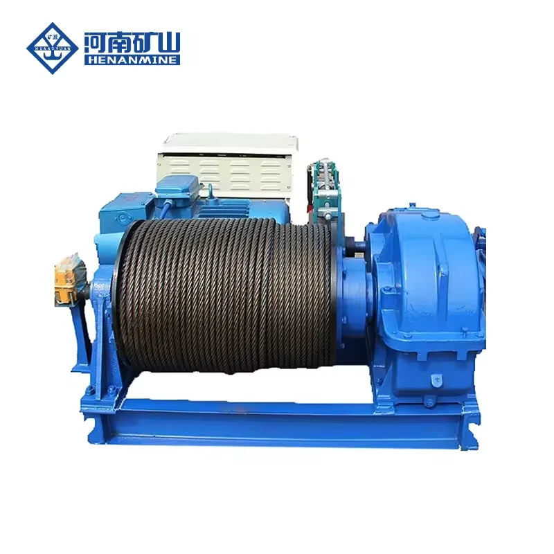
Move a rope line faster over a defined route.
View product ↗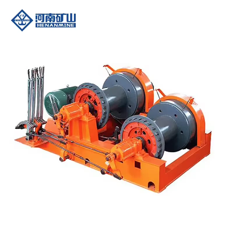
Use two separate rope drums when a project needs two defined line routes in one engineered arrangement.
View product ↗Compare rope speed, handling duty and drum arrangement before requesting a project quotation.
View collection ↗Use the answers to prepare one complete technical and commercial brief.
Discuss your winch requirementJM is a useful starting point for controlled, generally slower rope movement; JK starts with faster line travel. The correct selection follows the required working-layer pull, speed, rope length, brake and duty.
No. The model table lists rated load in kN from the supplier's winch specification. It does not independently certify a suspended lifting capacity or tell you the available pull on every drum layer.
Variants with the same listed 50 kN load can have different speeds and rope capacities. Ask for the selected model's complete technical schedule rather than mixing figures from separate rows.
State the usable travel, number of sheave passes, required dead wraps and rope diameter. The final drum and rope arrangement should meet that path without overfilling or excessive fleet angle.
A lifting request is reviewed as a separate duty. Specify the suspended load and working cycle so the brake, controls, rope system, structure, testing and local requirements can be assessed.
Specify the destination and acceptance requirements. Request the selected general arrangement, electrical and control documents, operating instructions, inspection records and agreed factory test evidence in the offer.
Single-unit enquiries are welcome. Minimum order, drawing approval, production and dispatch dates, warranty and installation support are confirmed for the selected package in writing.
Send the load path and operating conditions. We can then match the drum, rope, drive, brakes, controls and installation interface in a quotation that your team can actually compare.
Send my winch enquiry ↗