
Draw the entire steel range
List the longest and shortest pieces, thickness, shape and weight, including any cutouts or coating.
- Length and width
- Thickness and grade
- Weight and temperature
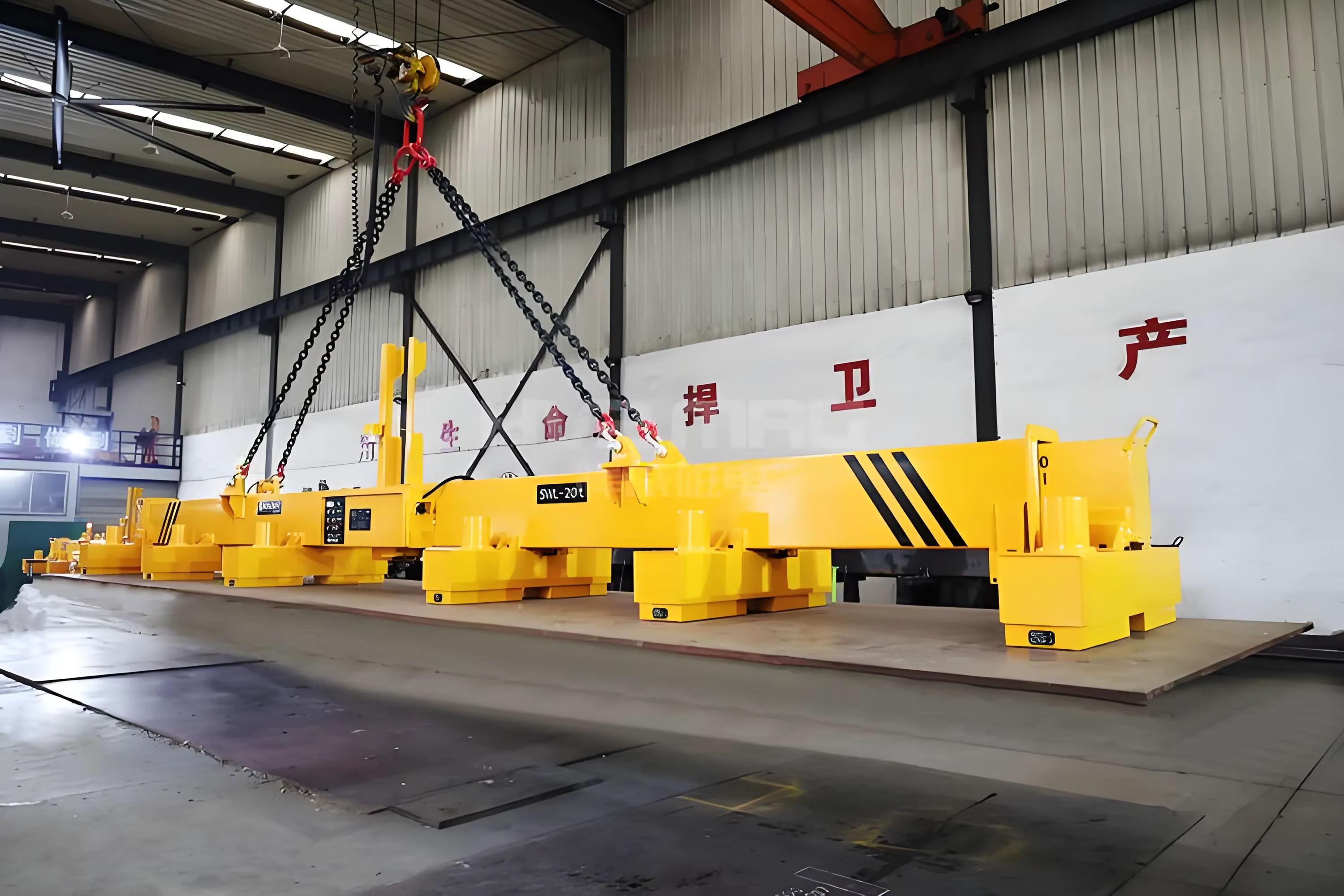
Lift long ferrous loads with multiple magnets supported by a beam rather than concentrating the load at one point. Beam length, suspension, magnet spacing and control zones follow the actual steel size and stiffness. The quotation should show the load from pickup to set-down, including sag, overhang, total beam mass and the crane's hook coverage.
Send plate or section drawings, grades and thicknesses, maximum length and weight, acceptable sag, pickup points, crane hook data and site power supply.
The selected attachment's minimum order and supply scope are confirmed in the written offer.
Review the loaded attachment, connection, operating cycle and site clearances before approval.
Agree inspection, documents, packing, schedule, site support and warranty before order placement.
Each beam must be sized to its workpiece and crane. The selected drawing should settle these linked parameters before production.
Swipe to compare the complete selected-unit parameters →
| Parameter | Buyer input | Selected-unit confirmation |
|---|---|---|
| Load envelope | Length, width, thickness and weight | Approved maximum/minimum workpiece |
| Material | Steel grade, coatings and temperature | Magnetic contact performance |
| Beam geometry | Pickup clearance and crane hook position | Length, suspension and headroom |
| Magnet layout | Allowed sag and overhang | Number and centre spacing |
| Controls | One load or multiple zones | Grouped or independent switching |
| Crane capacity | Hook rating and lifting height | Beam, magnets, rigging and steel |
| Site operation | Pickup/placement and cycle | Controls, power loss and test plan |
Capacity is conditional on the specific plate or section, surface contact, temperature and support pattern. Include the beam, magnets and rigging in the crane's total suspended load.
A long or flexible steel load can sag and peel away from a single contact point. Multiple magnets spaced along a lifting beam can support the load more evenly, but the final spacing and safe load need a drawing and trial for the actual material.
Review the configuration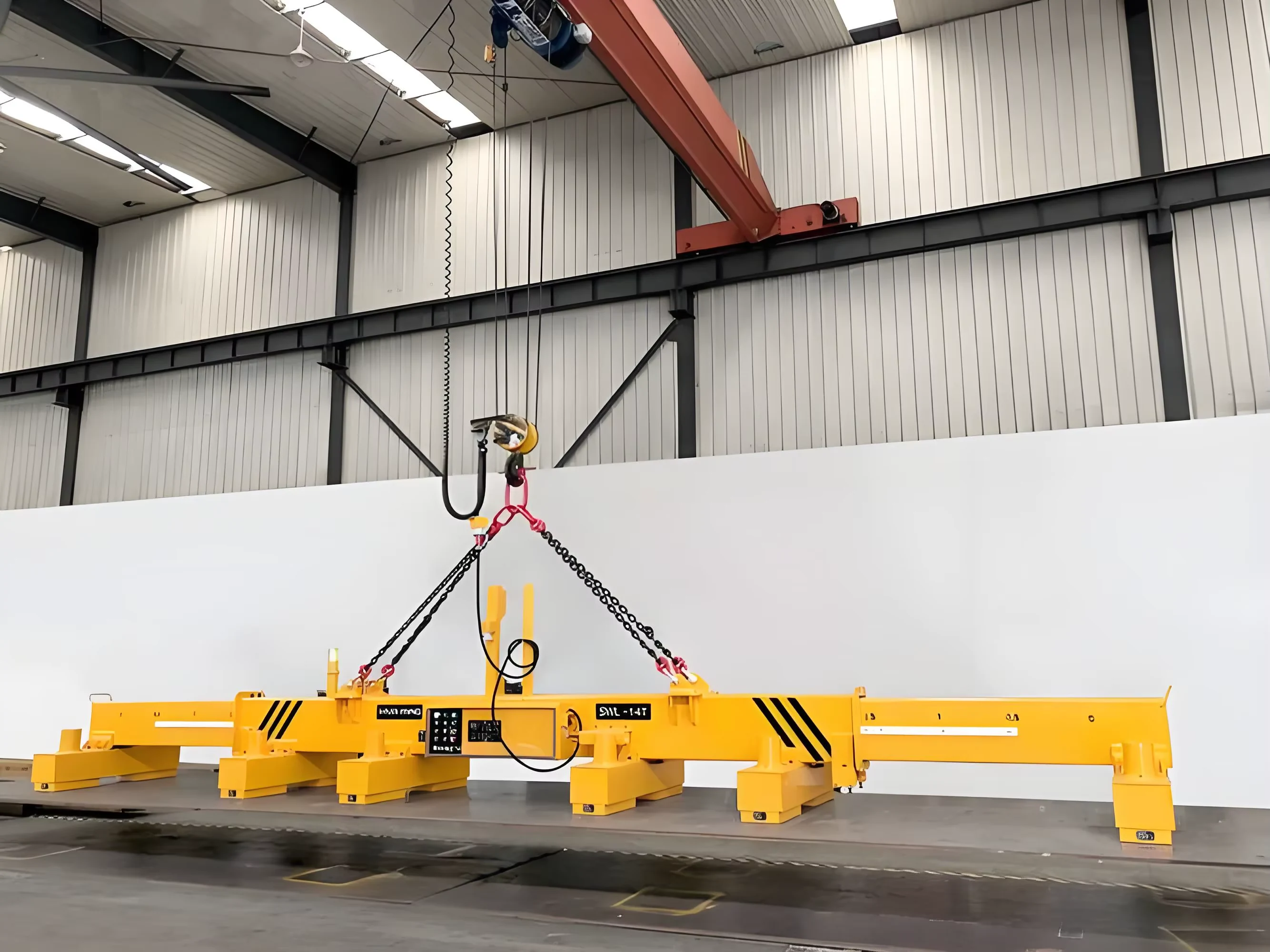
Pick and place plate with support points planned to limit excessive overhang, bending and contact loss.
Move sections between cutting, machining and assembly positions while keeping the workpiece orientation controlled.
Lift known lengths into storage or vehicles with enough hook coverage, set-down clearance and a controlled power-loss procedure.
Only suitable ferrous loads should be considered. Flexible plate and coated surfaces must be evaluated for real contact and sag, not a catalogue force figure alone. Compare the matching crane system.
Start with the longest, shortest and heaviest steel pieces that must be lifted. Set magnet number and spacing, beam length, suspension points and power supply for the least favourable load geometry, then confirm the approved lift on a project drawing.
Equipment price, crane modifications and site services should be separated so your team knows what is supplied and what remains to be done locally.
List the beam structure, magnet count and centres, suspension gear and complete self-weight.
Define the control cabinet, cable management, switching zones and power-loss response.
Agree load cases, trial lifts, drawings, test records, packing and on-site integration responsibilities.
The offer should connect your load data to one drawing, one equipment schedule and a clear inspection and handover plan. Production and freight dates are confirmed for that selected configuration.
List the destination standards and customer witness points before finalising the acceptance plan.
Confirm load, crane interface, environment, operating sequence and buyer requirements.
Approve dimensions, self-weight, selected components, controls and site responsibilities.
Complete the agreed functional and load-case checks, records and packing.
Coordinate transport, unloading, installation checks, operator instruction and handover.
Single-unit enquiries are welcome. The written offer confirms the selected design's minimum order and exactly what is supplied.
State applicable market and customer requirements. The offer lists the documents, inspections and tests available for the selected unit.
Drawing approval, production, inspection and shipping are separate milestones. A dated delivery programme follows the selected configuration.
Agree the warranty period and start date, covered components, replacement parts, installation guidance and any on-site service in the signed offer.
Ask for support termsAssign who supplies power, rope, hook connection, controls, rigging and commissioning equipment.
Agree inspection and functional checks around the material and lift the attachment was selected for.
Record the final model, serial number and wear parts so replacement components fit the supplied configuration.
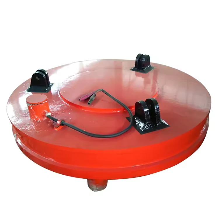
Pick up compatible ferrous scrap and cast-steel pieces without mechanical bucket jaws.
View product ↗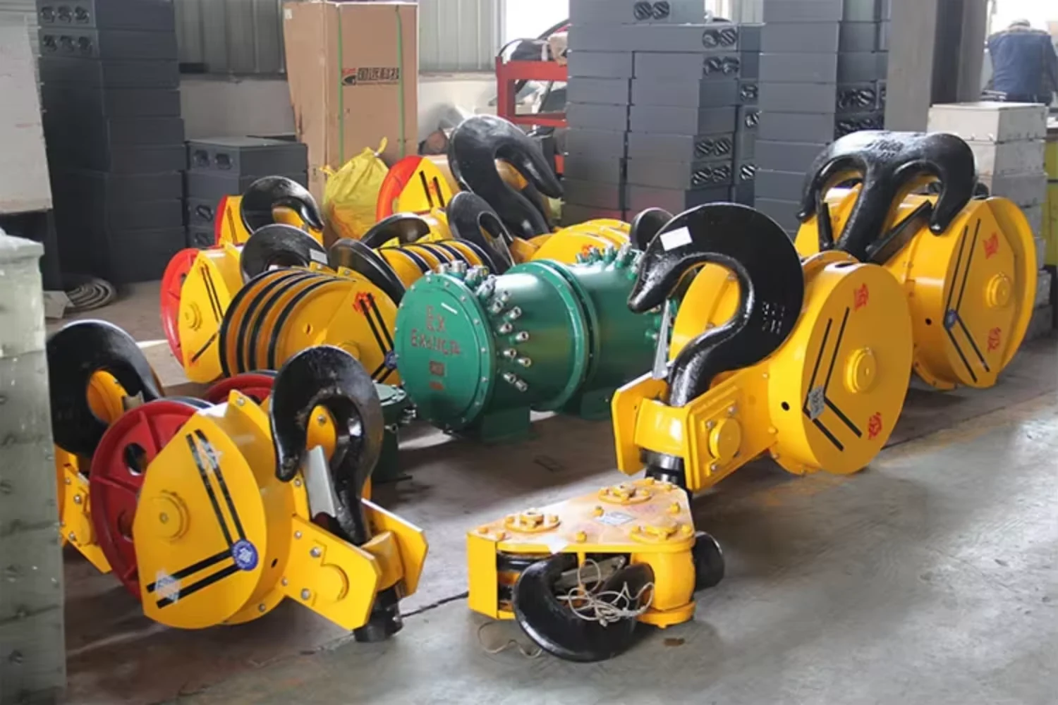
A replacement hook block must fit the complete hoist, not just share its tonnage label.
View product ↗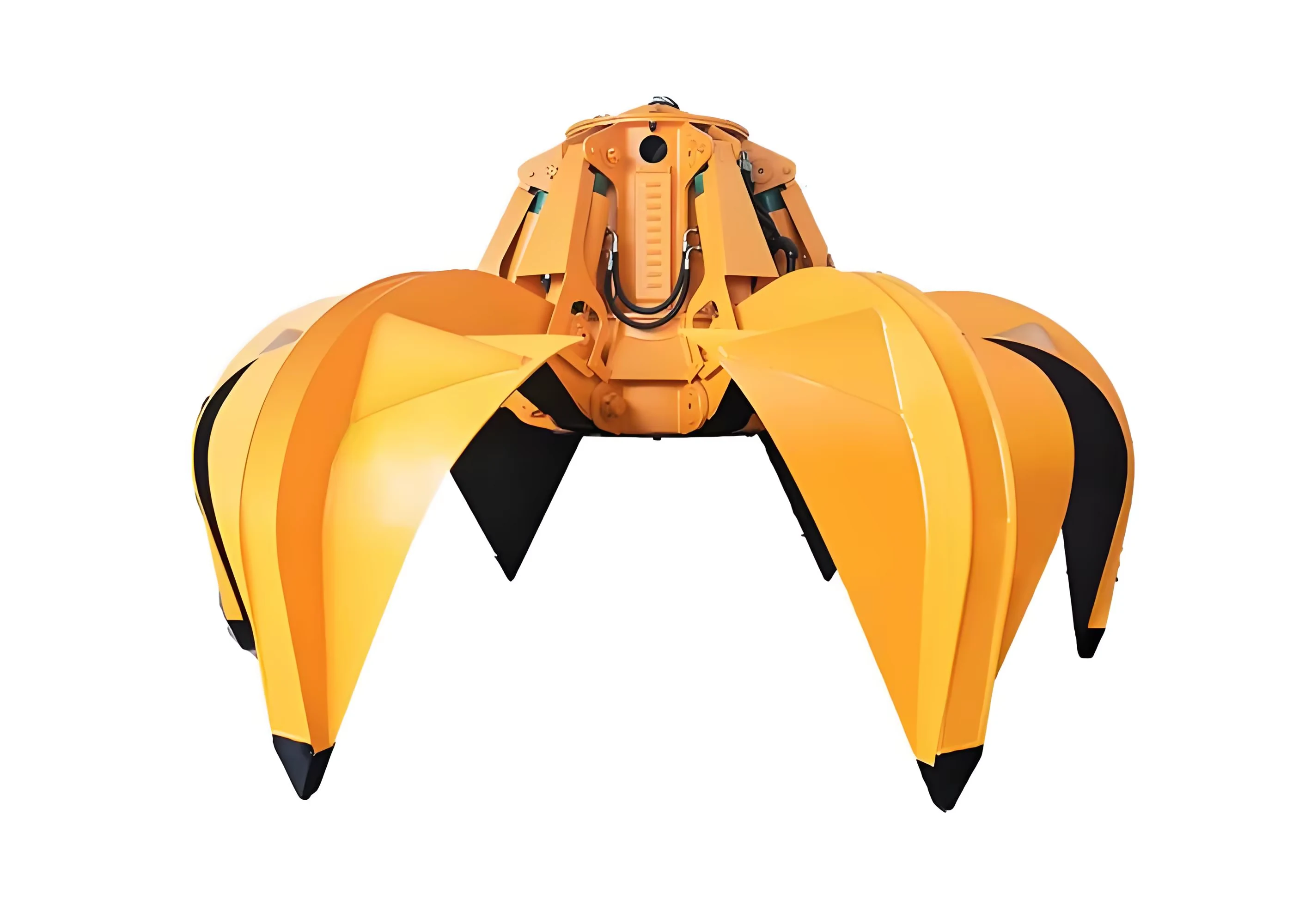
Curved tines close around long, irregular pieces that a two-shell bucket may not capture consistently.
View product ↗Use these answers to prepare one technical and commercial brief for the selected unit.
Discuss this attachmentNo. Length changes bending and support forces. The safe load depends on the selected beam, magnet spacing, steel contact and crane rating.
Only after the plate thickness, length, sag limit and support points are checked. More evenly distributed magnets may be necessary.
That is one option. The control logic can be defined around the load range, but every permitted mode needs an approved loading and test case.
The selected design must define detection, operating restrictions and safe set-down response. Do not assume the remaining magnets can carry the full load.
Provide hook height and approach, pickup and set-down zones, bay clearances, load lengths, vehicle height and available electrical supply.
Send plate or section drawings, grades and thicknesses, maximum length and weight, acceptable sag, pickup points, crane hook data and site power supply. The selected drawing and commercial offer can then identify the attachment, crane interface, documents, delivery and support.
Send my attachment enquiry ↗