Electromagnetic overhead cranes lift ferromagnetic material with a powered magnet or a magnetic carrier beam. Compare direct magnetic pickup, fixed and rotating beam arrangements, and combined grab-and-magnet cranes for scrap, plate and long steel.
Start with the material and pickup points. Choose a suspended magnet for direct pickup, a carrier beam for distributed lifting points, or a rotating layout when the load must change direction.
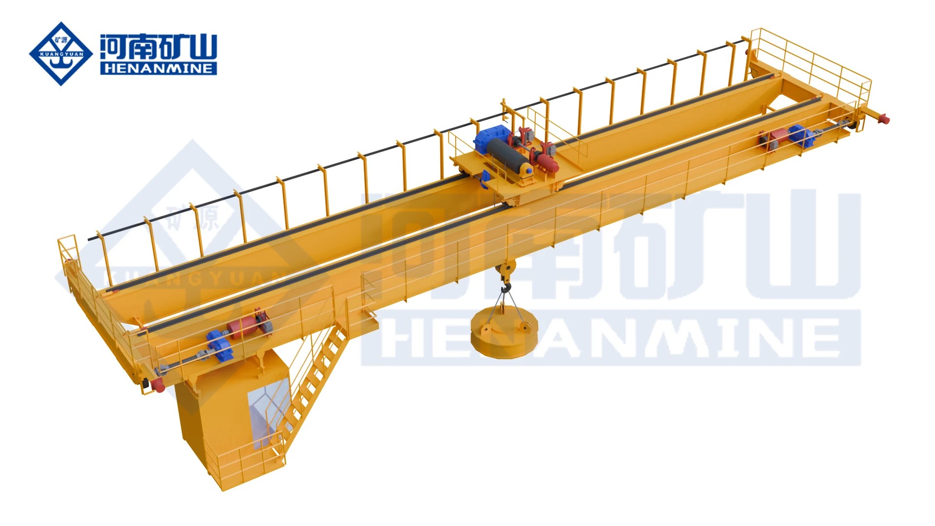
A hook-suspended lifting electromagnet handles ferromagnetic material; select a single-hoist or main-and-auxiliary-hook crane around the load and pickup conditions.
16/3.2 /20/5 /32/5 t; main hoist carries the magnet
Rated-load basis
The listed capacity includes the electromagnet self-weight
Usable material payload
Confirmed after magnet weight and the specified pickup conditions are established
Span options
10.5 /13.5 /16.5 /19.5 /22.5 /25.5 /28.5 /31.5 m
Reference duty
A6 in the matched configurations below
Single-hoist lifting height
16 m
Main / auxiliary lifting heights
16/3.2 t:16/18 m;20/5 t:12/14 m;32/5 t:16/18 m
Hoisting and trolley speeds
Matched to the rating in the configuration table
Bridge speed and wheel reactions
Matched to rating and span in the table below
Recommended rail
P43 in the listed configurations
Reference electrical supply
Three-phase AC 380 V, 50 Hz in the handbook; ordered supply confirmed in the offer
Magnet control
Energize and release control matched to the selected magnet
Power-loss holding package
Holding duration, alarms, test conditions and recovery procedure specified in the offer
Hook rotation in the reference magnet setup
The hook swivel is locked while the magnet is in use
QC matched hoisting configurations
Scroll across to see every column.
Rated configuration (t)
Lifting height (m)
Hoisting (m/min)
Trolley (m/min)
Duty
Attachment arrangement
5
16
15.6
39.5
A6
Single magnet hoist
10
16
13
43.8
A6
Single magnet hoist
16
16
13
44.5
A6
Single magnet hoist
16/3.2
16 /18
13 /14.6
44.6
A6
Main magnet / auxiliary hook
20/5
12 /14
12.6 /15.5
44.6
A6
Main magnet / auxiliary hook
32/5
16 /18
9.5 /15.5
43.4
A6
Main magnet / auxiliary hook
A slash separates main and auxiliary ratings or movements, not simultaneous added payload. The magnet self-weight forms part of the rated suspended load.
QC matched span, bridge speed and maximum wheel load
Scroll across to see every column.
Rated configuration (t)
Span (m)
Bridge travel (m/min)
Max. wheel load (kN)
Duty
5
10.5
92.7
72
A6
5
13.5
92.7
79
A6
5
16.5
92.7
87
A6
5
19.5
92.7
94
A6
5
22.5
92.7
104
A6
5
25.5
92.7
114
A6
5
28.5
93.7
122
A6
5
31.5
93.7
134
A6
10
10.5
92.7
115
A6
10
13.5
92.7
122
A6
10
16.5
92.7
129
A6
10
19.5
93.7
138
A6
10
22.5
93.7
145
A6
10
25.5
86.4
157
A6
10
28.5
86.4
164
A6
10
31.5
86.4
173
A6
16
10.5
76
143
A6
16
13.5
76
153
A6
16
16.5
76
162
A6
16
19.5
89
173
A6
16
22.5
89
184
A6
16
25.5
89
194
A6
16
28.5
89
204
A6
16
31.5
89
213
A6
16/3.2
10.5
76
146
A6
16/3.2
13.5
76
153
A6
16/3.2
16.5
76
161
A6
16/3.2
19.5
76
174
A6
16/3.2
22.5
76
182
A6
16/3.2
25.5
89
193
A6
16/3.2
28.5
89
204
A6
16/3.2
31.5
89
214
A6
20/5
10.5
76
170
A6
20/5
13.5
76
177
A6
20/5
16.5
76
187
A6
20/5
19.5
89
201
A6
20/5
22.5
89
210
A6
20/5
25.5
89
223
A6
20/5
28.5
89
234
A6
20/5
31.5
89
245
A6
32/5
10.5
89
245
A6
32/5
13.5
89
258
A6
32/5
16.5
89
272
A6
32/5
19.5
75.3
289
A6
32/5
22.5
75.3
304
A6
32/5
25.5
75.3
317
A6
32/5
28.5
75.3
327
A6
32/5
31.5
75.3
341
A6
These are matched reference configurations. Final building reactions and speeds follow the selected crane drawing.
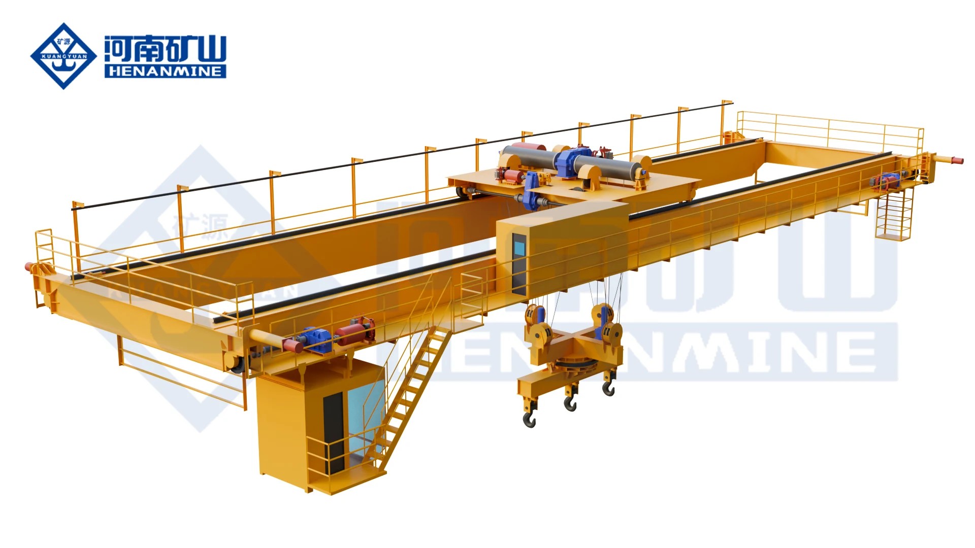
An electromagnetic carrier beam spreads pickup points along steel plate, sections and ingots; the beam, magnets and crane are selected as one lifting package.
Base bridge with twin hooks shown; the carrier beam and magnets are specified with the ordered lifting package.
Double girder bridge; single trolley with main and auxiliary lifting mechanisms
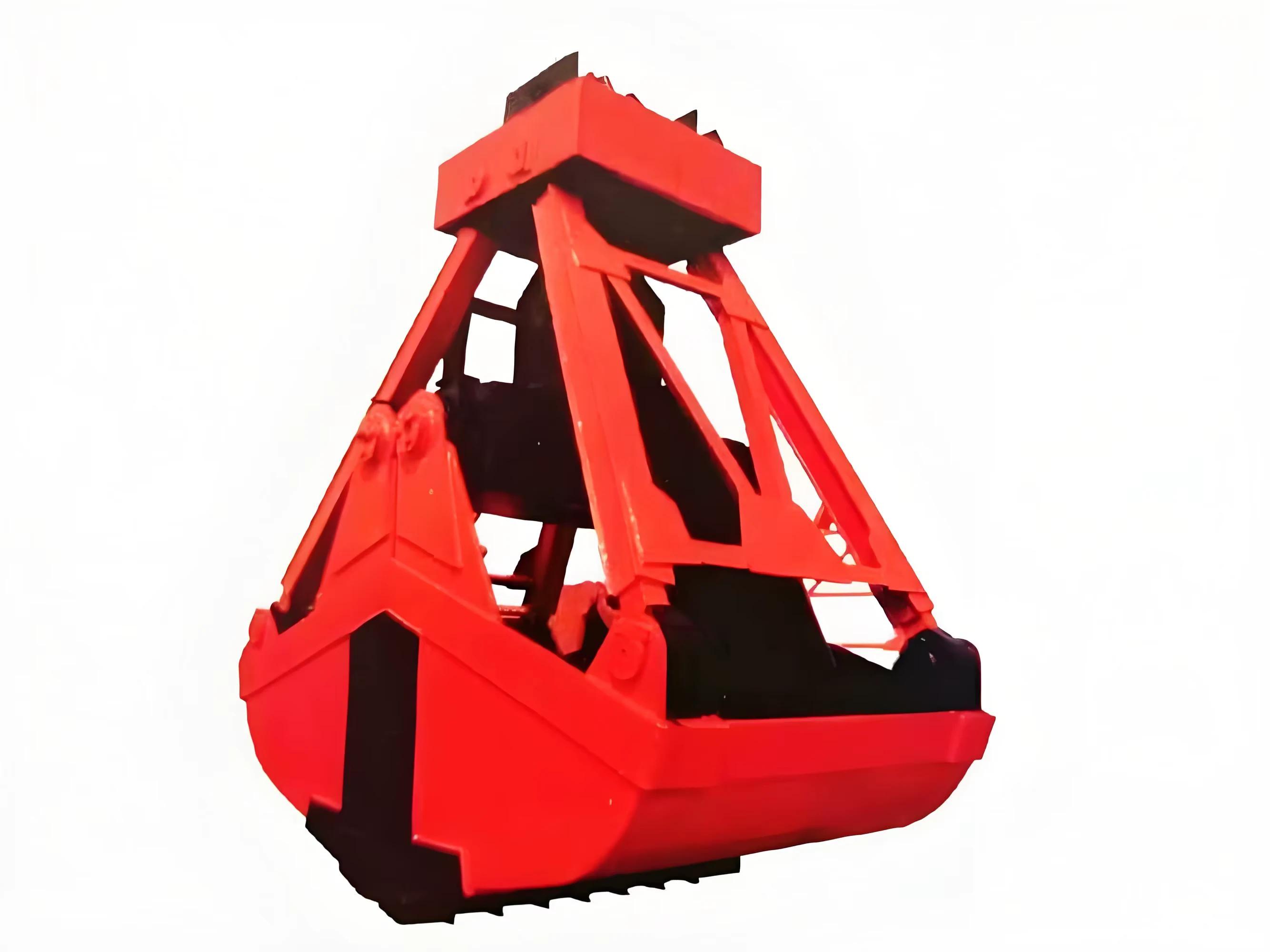
Grab mechanism
Two matching winches operate the holding and opening/closing ropes
Magnet mechanism
Separate hoisting mechanism with an electromagnet suspended from its hook
Mode ratings
5/5 /10/10 /16/16 t; slash separates grab and magnet modes
Rated-load basis
Grab self-weight is included; the magnet package also consumes part of the magnetic mode rating
Span options
5/5 t: 10.5–31.5 m; 10/10 t: 13.5–31.5 m; 16/16 t: 19.5–31.5 m, in the listed 3 m steps
Reference duty
A6
Lifting heights and speeds
Grab and magnet movements remain separate in the matched table
Controls
Cabin and radio operation described for the reference configuration
Magnet package
MW1-6, MW1-16 or MW1-45 examples matched to the crane rating
Grab selection
Grab volume and self-weight selected for the stated material bulk density
Wheel reactions
Indoor/outdoor values matched to rating and span
Reference rail
P43 for 5/5 and 10/10 t;QU70 for 16/16 t
Reference electrical supply
Three-phase AC 380 V, 50 Hz in the handbook; ordered supply confirmed in the offer
Magnet power-loss holding
Selected backup supply, holding duration and recovery procedure specified in the offer
QP separate grab and magnet configurations
Scroll across to see every column.
Grab / magnet rating (t)
Listed spans (m)
Grab / magnet lift (m)
Grab / magnet hoisting (m/min)
Trolley (m/min)
Duty
Rail
5/5
10.5 /13.5 /16.5 /19.5 /22.5 /25.5 /28.5 /31.5
20 /16
40.1 /15.6
44.6
A6
P43
10/10
13.5 /16.5 /19.5 /22.5 /25.5 /28.5 /31.5
18 /22
40 /10.4
45.6
A6
P43
16/16
19.5 /22.5 /25.5 /28.5 /31.5
22 /22
41.8 /13
43.2
A6
QU70
Grab and magnetic modes have separate ratings, hook heights and speeds. Do not add the slash ratings as combined steel payload or imply simultaneous use.
QP matched span and wheel-reaction configurations
Scroll across to see every column.
Grab / magnet rating (t)
Span (m)
Bridge (m/min)
Max. indoor wheel load (kN)
Max. outdoor wheel load (kN)
5/5
10.5
93.7
106
111
5/5
13.5
93.7
113
118
5/5
16.5
93.7
120
125
5/5
19.5
93.7
131
136
5/5
22.5
93.7
134
140
5/5
25.5
86.4
151
156
5/5
28.5
86.4
161
166
5/5
31.5
86.4
171
177
10/10
13.5
76
159
163
10/10
16.5
76
173
177
10/10
19.5
89
186
190
10/10
22.5
89
196
199
10/10
25.5
89
209
213
10/10
28.5
89
219
223
10/10
31.5
89
229
233
16/16
19.5
75.3
241
245
16/16
22.5
75.3
253
258
16/16
25.5
75.3
264
271
16/16
28.5
75.3
275
281
16/16
31.5
75.3
283
289
Reference wheel reactions are shown separately for indoor and outdoor crane configurations. Use the final crane drawing for the building interface.
QP magnet package examples: pickup and self-weight stay separate
Scroll across to see every column.
Magnetic-mode crane rating (t)
Magnet model
Listed pickup reference (kg)
Magnet self-weight (kg)
Magnet diameter (mm)
5
MW1-6
4540
460
776
5
MW1-16
3330
1670
1180
10
MW1-16
8330
1670
1180
16
MW1-16
14330
1670
1180
16
MW1-45
10450
5550
1650
These are named handbook package examples, not a guarantee for every steel grade, thickness, temperature or contact surface. The pickup reference and magnet weight use separate kg columns; the full crane rating is not all usable steel payload. Confirm the selected magnet and pickup conditions in the technical offer.
Rated crane load and usable steel payload are different. Confirm the weight of the magnet, beam and rigging, then check the selected magnet’s pickup capacity for the actual steel, temperature and contact conditions.
Price & supply scope
How much does an electromagnetic overhead crane cost?
The crane, magnet and electrical package must be priced together. Capacity, span, lifting height, working duty, magnet quantity, beam arrangement and rotation can change the equipment supplied.
Preliminary QC configuration budgets · USD
Crane configuration
Rated crane capacity*
Span
Lifting height
Duty / control
Preliminary equipment budget (USD)
QC with hook-suspended electromagnet
10 t
16.5 m
13 m
A6 / cabin control
USD 32,000–46,000 · preliminary estimate
QC with hook-suspended electromagnet
16 t
22.5 m
12 m
A6 / cabin control
USD 44,000–63,000 · preliminary estimate
These crane ratings include electromagnet self-weight. Usable steel payload must also satisfy the selected magnet’s pickup capacity for the stated material, temperature and contact conditions. The USD ranges are preliminary equipment estimates covering the bridge, lifting trolley, single magnet, estimated rectifier/release and cable equipment, cabin controls, factory tests and packing. An application-specific backup holding and recovery package, runway/site power works, freight, duties/taxes, installation and commissioning require separate confirmation and pricing. These are planning allowances, not binding quotations.
Price factor
What to compare in the offer
Steel and pickup task
Specify the steel type, dimensions, temperature, contact condition and the useful material weight required per lift.
Crane and attachment layout
Compare rated suspended load, span, lifting height, duty, magnet spacing, beam length and any rotation or grab mode.
Magnet power and controls
Identify excitation and release controls, cable equipment and any specified backup holding, monitoring or alarms.
Delivery and site scope
List crane equipment and attachments, then confirm rails, power feed, freight, installation, commissioning and training.
QL, YC, QLC, QJ and QP need a quotation for the selected beam, attachment and operating modes. Ask for an itemized offer on a stated delivery basis.
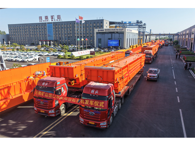
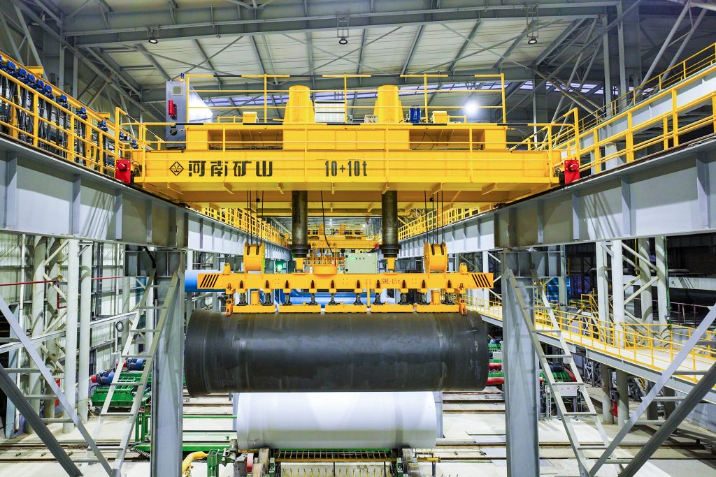
Henan Mine Crane developed an automated carrier-beam crane with rigid guide columns, dual lifting motors and electro-permanent magnetic attachments. Its controls support automatic dispatch, same-bay crane avoidance and local or remote operation.
The photographed equipment handles a steel coil with an electro-permanent magnetic beam. This custom development example uses a different magnetic holding method from a conventional continuously excited electromagnet.
Should I choose a suspended magnet or a magnetic carrier beam?
The choice depends on the material shape and pickup arrangement. QC uses a hook-suspended electromagnet. A carrier beam provides several pickup points along plate, sections or other long steel. Send the shortest and longest pieces, their weights and the intended single-piece or batch pickup.
Does a 10 t crane rating mean 10 t of steel payload?
Do not assume that it does. The stated crane rating may include magnet and lifting-attachment weight, as in the QC price examples above. The magnet’s pickup limit also depends on the material, thickness, temperature, surface and contact. The quotation must state both the permitted suspended load and the useful steel payload.
What is the difference between upper and lower beam rotation?
YC rotates the lifting arrangement above the lower trolley. QLC rotates the magnetic carrier beam below the trolley. QJ is a lower-rotating carrier-beam platform with a selected magnetic or mechanical attachment. Specify the required turning angle and load envelope so the correct layout and clearances can be selected.
How are grab and magnet capacities specified on QP?
QP has separate grab and magnetic handling modes. A notation such as 5/5 t identifies the ratings of those modes; it is not an instruction to add them into a combined lift. State the material for each mode and confirm the grab, magnet and permitted operating sequence in the offer.
What happens if power to the magnet is interrupted?
The response depends on the selected magnetic system and its controls. Confirm the holding method, any backup supply, alarms, release interlocks and required acceptance checks for the actual load. Conventional electromagnetic and electro-permanent systems use different holding methods; do not assume the same power-loss behaviour or holding time for every system.
What information is needed for a magnetic crane quotation?
Send the steel type, size and weight range, the pickup quantity per lift, approximate crane span, lifting height and project location. Tell us whether you handle hot material, turn the load or switch between a grab and a magnet. A workshop sketch helps define the route and landing positions.
Compare the range
Electromagnetic crane specification comparison
Compare pickup arrangements and the available configuration data. Select the full product name to view its details.
Grab and magnetic handling in separate operating modes
QC main/auxiliary ratings and QP grab/magnet mode ratings describe different arrangements. Beam, magnet and rigging weight affect useful material payload. Configuration values and attachment performance are confirmed for the actual handling task.
Get an electromagnetic overhead crane quote
Send the steel type, dimensions and weight range, required pickup per lift, span and lifting height. Tell us whether the load must turn and where it must land.
Include the project location and any bay sketch available. Ask for the crane, magnetic attachment, controls and delivery scope together.