Skip to content
Henan mine crane co., ltd. Get a project quote
QL / MAGNETIC & STEEL HANDLING

QL Electromagnetic Carrier Beam Overhead Crane

Support long ferromagnetic steel at several magnetic pickup points along a carrier beam. QL combines the bridge, lifting arrangement, beam and magnets for plate, ingots and sections whose length and stiffness call for distributed support. Select beam length, magnet spacing and any rotation from the full product range and the route between pickup and landing.

Lifting arrangement
Magnetic carrier beam
Pickup pattern
Multiple selected magnet positions
Beam orientation
Rotation selected with the order
Net steel payload
After beam and attachment allowance
Material-matched liftingDefined load & duty

Start with the information you already have. A load drawing and workshop sketch help us recommend a configuration.

01
Spread pickup across the product

Beam length, magnet count and contact positions follow the shortest and longest products and their stiffness. The selected layout supports the intended material range rather than one convenient maximum-size sample.

02
Match storage and production directions

Choose the beam's working orientation from the bay plan. Where the route needs a horizontal turn, a selected rotating arrangement can place the steel in the required direction, with its full swept area checked against the plant.

03
Compare usable payload with the complete beam

The listed rotating ratings include the carrier beam and dedicated attachments. Establish their tare and permitted load distribution so purchasing can compare the steel payload each complete proposal will actually handle.

Rotating QL carrier-beam overhead crane with multiple rectangular lifting magnets
Rotating QL carrier beam with multiple lifting magnets in a steel-handling workshop.
01 / APPLICATIONS

Support long steel along the pickup length.

01

Plate storage and process transfer

Arrange magnets along compatible steel plate for movement between storage rows and process positions. Provide length, width and thickness ranges, surface and stack conditions, and whether each lift should pick one plate or a defined batch.

02

Sections, ingots and long stock

Select magnetic contact positions for the product shape and centre of gravity. Describe the shortest product as well as the heaviest so beam geometry, magnet spacing and load distribution cover the intended range.

03

Oriented stacking and dispatch

Use a selected rotating QL arrangement where receiving, storage and landing positions have different horizontal directions. Check beam ends and the complete steel sweep at pickup, through the turn and at the final placement.

QL identifies a carrier-beam arrangement. The three matched numerical reference rows describe selected rotating configurations; they do not make rotation a standard feature of every QL order.

02 / TECHNICAL SPECIFICATIONS

QL specifications and configuration options

Compare the available options for your lifting task. Capacity, span, lift height and speed are matched in the selected configuration.

ModelQL
Lifting arrangementElectromagnetic carrier beam; beam orientation and rotation selected with the order
Listed rotating capacity selections10+10 / 12.5+12.5 / 13.5+13.5 t
Listed rotating spans28.5 / 28.5 / 31.5 m, in the same capacity order
Listed rotating lifting heights16 / 10 / 13 m, in the same capacity order
Listed rotating working dutyA6 / A7 / A7, in the same capacity order
Listed rotating hoisting speed11.4 m/min
Listed trolley / bridge travel38 / 88 m/min
Listed rotation range / speed±180° / 0.8 r/min for the rotating configuration
Magnet holding on power loss15–30 minute battery-holding package; selected duration and test load in the order
Power supplyListed rotating configurations: 380 V / 50 Hz, three-phase; magnet circuit specified separately
Capacity definitionListed rotating capacity includes carrier beam and dedicated lifting attachments; net steel payload stated separately
Operating environmentListed rotating configurations: indoor; outdoor, dust and temperature package by specification
Magnet patternBeam length, magnet quantity and spacing matched to steel dimensions and pickup conditions
Power calculationCrane drive power and dedicated attachment power identified separately

The listed 15–30 min battery-holding time is a manufacturer reference. Confirm the supplied magnet, holding load and contact conditions, required duration, monitoring and acceptance test in the order. Backup magnet supply does not establish powered crane travel.

Compare model configurations

Rotating QL ratingSpanLiftDutyHoisting speedRotation speed
10+10 t28.5 m16 mA611.4 m/min0.8 r/min
12.5+12.5 t28.5 m10 mA711.4 m/min0.8 r/min
13.5+13.5 t31.5 m13 mA711.4 m/min0.8 r/min

These are indoor rotating QL selections with ±180° beam rotation, 38 m/min trolley travel and 88 m/min bridge travel. Ratings include the beam and dedicated attachments. Keep each capacity, span, lift and duty together.

Runway data for the rotating QL arrangements

Rotating ratingSpanDutyMaximum wheel loadRecommended bridge rail
10+10 t28.5 mA6360 kNQU80
12.5+12.5 t28.5 mA7373 kNQU80
13.5+13.5 t31.5 mA7228 kNQU80

These data belong to the matched indoor rotating configurations. The selected crane arrangement and attachment package determine the final installation data.

03 / EQUIPMENT VIEWS

Review the beam support and magnetic pickup pattern.

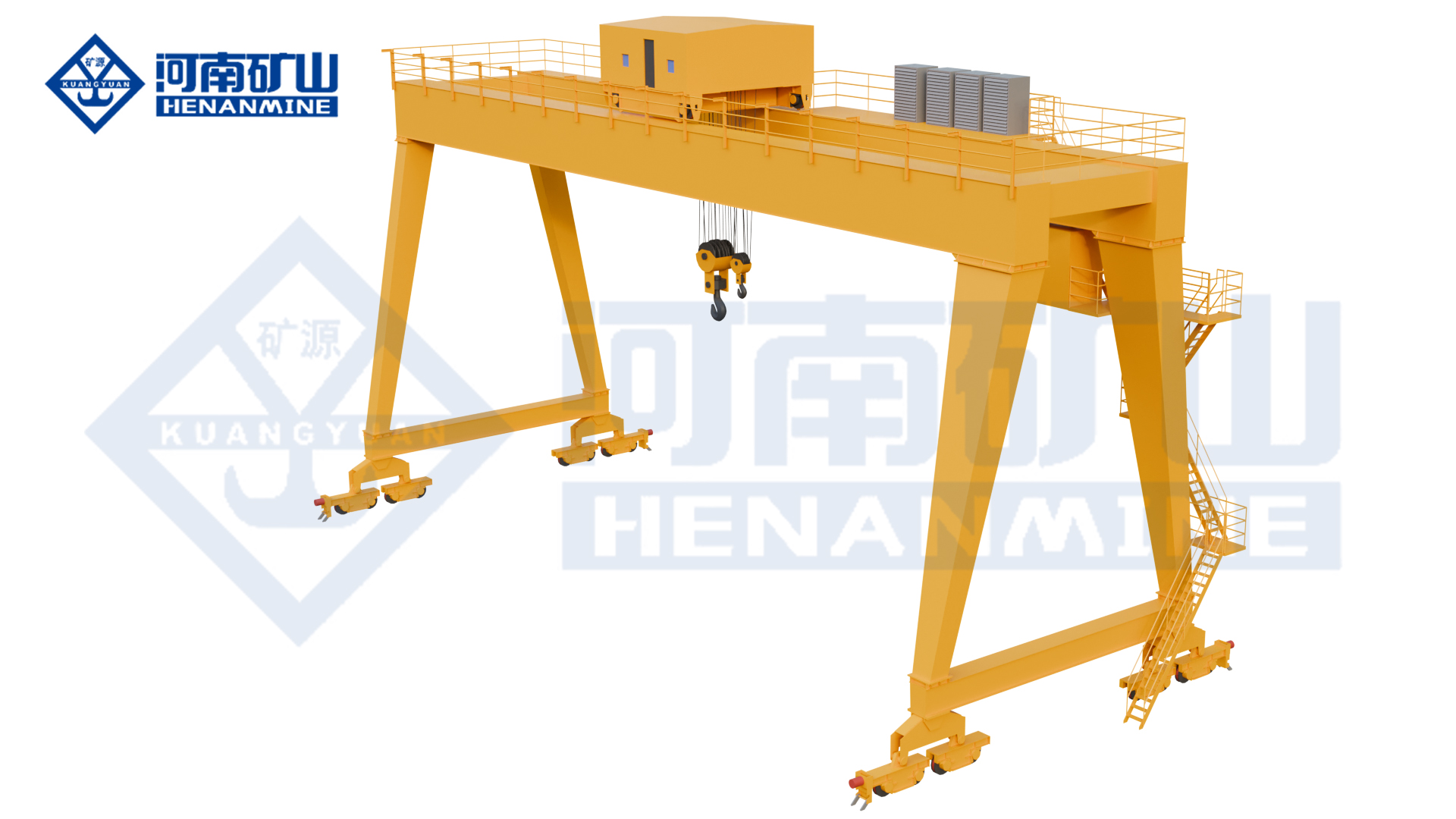
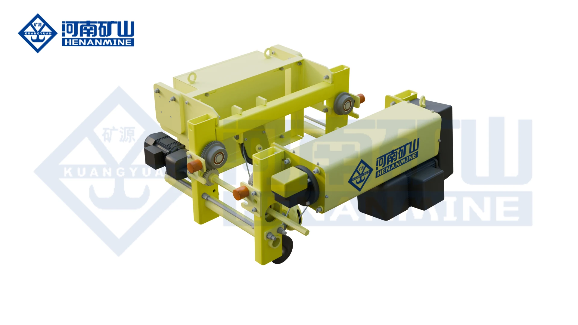
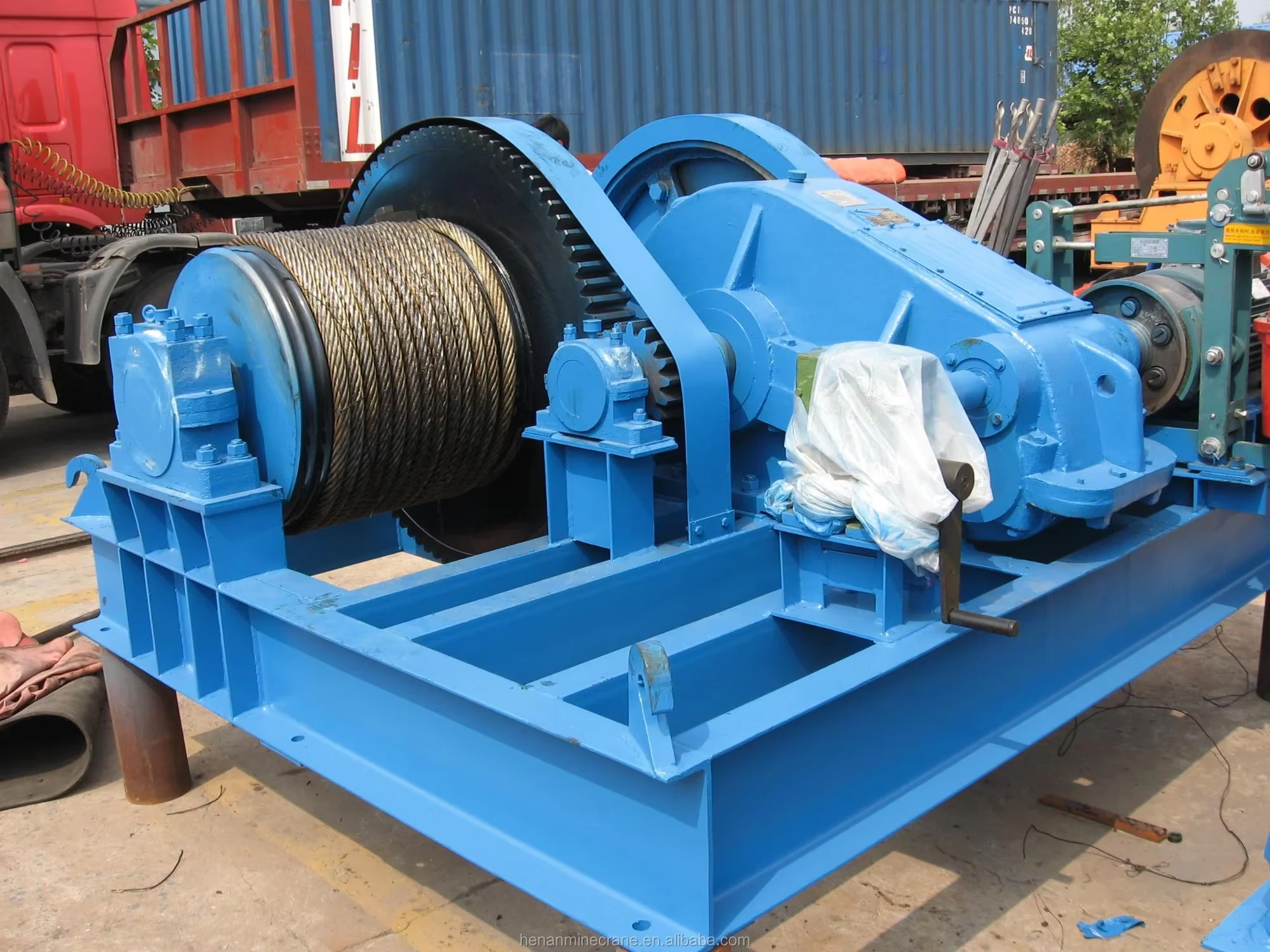
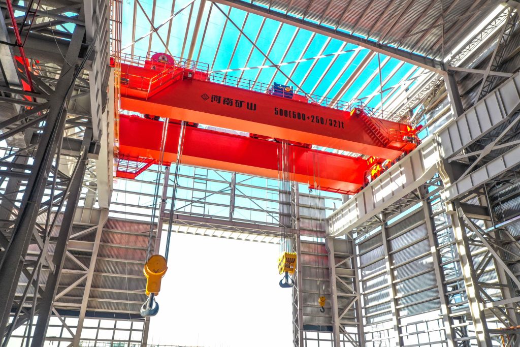
The first three structural renderings show the bridge and paired winch-and-hook lifting arrangement, without the selected carrier beam and magnets fitted. The installed photograph shows one rotating beam example. Neither establishes the supplied attachments or makes rotation standard across QL: the order and final drawing identify beam length, magnet count and spacing, attachment weights and any rotation mechanism.

QL double-girder bridge with two hoisting units and two suspended hooks
QL bridge and twin lifting arrangement
QL overhead bridge showing two hoisting drums, two hooks and the service walkway
QL twin-hoist bridge arrangement
04 / CONFIGURATION

Configure QL around your production task.

Develop the beam and magnet pattern around your product range before finalising crane capacity. Keep each listed rotating reference's rating, span, lift, duty and rotation data together, then confirm the ordered beam arrangement and usable steel payload.

QL double-girder bridge with two hoisting units and two suspended hooks
QL bridge and twin lifting arrangement
01 / SELECTION

Full product range and pickup task

Provide minimum and maximum length, width, thickness and mass, with steel grade, surface condition and pickup temperature. Identify single-piece or batch handling and any required single-sheet separation from a stack.

02 / SELECTION

Beam length and magnet spacing

Choose pickup positions around product stiffness, permissible overhang and contact faces. Specify any required spacing adjustment and include the beam, magnets, suspension and cables in the complete suspended-load calculation.

03 / SELECTION

Orientation and any rotation function

Show the beam direction at pickup and landing. The listed rotating examples use ±180° at 0.8 r/min; the ordered arrangement defines its actual rotation, limits, controls and permitted movement with the selected steel load.

04 / SELECTION

Coverage, headroom and reactions

Set rail-centre span, runway length, lifting levels and maximum stack heights from the bay plan. Check suspended beam depth, trolley approaches, roof and column clearances, the load sweep and maximum wheel reactions.

05 / SELECTION

Magnet power and battery holding

The manufacturer lists a selected 15–30 minute battery-holding package for QL. Specify duration for the actual magnets, load and contact conditions, with battery status monitoring, alarms and an acceptance test; magnet holding does not establish powered crane movement.

06 / SELECTION

Cycle, environment and controls

State lifts per hour, load spectrum, shifts and any rotation frequency. The listed rotating configurations are indoor references; define outdoor exposure, dust, ambient and steel temperatures separately, with the required operator position and destination power.

05 / PURCHASING & HANDOVER

Define the equipment,
documents and delivery scope.

Ask for one QL equipment schedule covering the bridge, lifting arrangement, carrier beam, magnets, excitation, cables and controls. Identify any rotation and battery-holding equipment explicitly, with usable steel payload, test conditions, drawings, delivery milestones and site responsibilities attached to the same selection.

List the complete carrier-beam package

Name the beam, lifting interfaces, magnets and suspension with their weights, pickup positions and selected controls. Identify rotation, spacing adjustment, power feed, rails and runway work as included or separately supplied items.

Compare the same product envelope

Beam length, magnet quantity, adjustment needs, net steel payload, rotation, duty and backup holding affect cost. Compare quotations against the same minimum and maximum products, contact conditions and required handling sequence.

Agree material-specific acceptance

Request the arrangement and beam drawings, tare and net payload schedule, wheel reactions, electrical documents and manuals. Define pickup, release, single-sheet checks where required, any rotation limits and power-loss holding tests using stated representative material.

Plan approval, manufacture and transport

Agree milestones for product data, magnet and beam selection, drawings, manufacture, factory checks and dispatch. Define beam packing, transport dimensions, freight, unloading and access so logistics follow the selected arrangement.

Prepare for commissioning in the bay

Allocate bridge and beam assembly, suspension and cable setup, magnet-power connection and site test loads. Include the actual pickup and landing orientations, ordered rotation functions and backup holding checks in commissioning and operator training.

Specify support for beam and power equipment

Confirm warranty terms and service responsibilities for the crane, beam, magnets, selected rotation and battery package. Request inspection and battery-maintenance instructions plus recommended rope, brake, cable, control and rotation-component spares where fitted.

01Define the steel range

Share dimensions, thicknesses, grades, contact surfaces, temperature and single-piece or batch pickup requirements.

02Approve the handling layout

Review beam length, magnet spacing, net payload, load distribution and the pickup-to-landing orientation.

03Confirm supply and acceptance

Agree any rotation, holding duration and test conditions, drawings, delivery milestones and site-service boundaries.

04Verify the selected product flow

Commission pickup, travel, placement, release and ordered power-loss functions, then hand over operating and maintenance records.

DOCUMENTS TO AGREE

Technical schedule · General arrangement · Attachment interface · Runway loads · Electrical information · Safety-function description · Agreed inspection records · Operation and maintenance manuals

07 / PROCUREMENT QUESTIONS

Before you order
your QL crane.

Review the lifting task, configuration and quotation scope. We can help develop a crane proposal from the project information available.

Why choose QL instead of a hook-suspended QC magnet?

QL distributes multiple magnets along a carrier beam, which suits long steel needing several pickup positions. QC uses one hook-suspended magnetic lifting arrangement. Product length, stiffness, available contact faces and the required pickup pattern determine the more useful approach.

Does every QL crane rotate the beam?

No. QL identifies the magnetic carrier-beam arrangement; orientation and any rotation function are selected for the job. The three matched reference rows here describe rotating QL configurations. Confirm the actual beam mechanism, movement and limits in the order.

How much steel can a 10+10 t rotating selection handle?

The listed rotating rating includes the carrier beam and dedicated lifting attachments. Their weights, permitted load distribution and magnet pickup performance determine usable steel payload. The plus marking belongs to the paired beam-lifting arrangement and does not establish two unrestricted independent hook jobs or an automatic combined payload.

Can the same beam lift short and long products?

It can be selected for a defined product range. Send the shortest and longest dimensions, thickness, stiffness and weight, together with permissible contact positions and overhang. The proposal identifies magnet spacing and any adjustment needed to cover that range.

Can QL pick one thin plate from a stack?

State single-sheet pickup as a separate handling requirement. Plate grade, thickness, flatness, surface and stack conditions affect the task. Select the magnet and controls for it and agree separation, release and residual-magnetism checks on representative plates; a general beam rating does not prove single-sheet separation.

What does the 15–30 minute holding reference mean?

It describes a selected battery package for continuing magnet holding after loss of the main supply. The order fixes the duration, magnets, test load, material and contact conditions, battery state requirements, monitoring, alarms and recovery procedure. It does not by itself provide bridge travel, trolley travel or powered lowering.

How should we check a rotating arrangement in our workshop?

Show the beam and steel orientation at pickup and landing, the longest load, stack heights, columns and nearby equipment. Check the entire swept area and suspended depth. The listed ±180° and 0.8 r/min belong to the rotating reference configurations; the ordered arrangement defines the permitted motion and operating limits.

Can QL handle hot stock or work outdoors?

Both require selection for stated conditions. Give steel pickup temperature and exposure time separately from ambient temperature, dust and weather. The numerical rotating references are indoor configurations; the offer must identify the magnet, cables and environmental package for your installation.

Does battery holding make this an electro-permanent system?

No. The QL arrangement described here uses electrically excited lifting magnets and a specified backup supply where selected. Electro-permanent magnets use switching pulses to change a permanent-magnet circuit's state. An electro-permanent alternative requires a separate attachment, control and acceptance specification.

Which details should the QL purchase order settle?

Confirm the product range, beam and magnet layout, tare and usable steel payload, load distribution, crane geometry and duty. Identify any rotation and backup holding, representative pickup and release tests, drawings and manuals, production and delivery milestones, installation and training responsibilities, warranty terms and recommended spares.

GET A CONFIGURED QUOTATION

Request your QL
technical proposal.

Send the shortest and longest steel products, their thickness and weight range, and the direction they must face at pickup and landing. We can use those details with your bay sketch to develop a QL beam, magnet pattern and crane selection.

  • Crane and lifting device matched to the load
  • Clear configuration and supply boundaries
  • Drawing, testing and site-support scope

info@cranehenanmine.com

PRODUCT SELECTEDQL Electromagnetic Carrier Beam Overhead Crane

Include surface photographs, steel grade, temperature, net pickup target and single-piece or batch requirements. Add span, lifting levels, shifts, site power and destination when available.

↑
QL Overhead CraneRequest your project quotation
Get a quotation ↗
QL equipment gallery
Enlarged product image