
Select the circuit
For three-phase AC, use line-to-line voltage and line current. The tool applies the corresponding circuit multiplier.
Bridge cranes for workshops and production lines.
Explore Overhead Cranes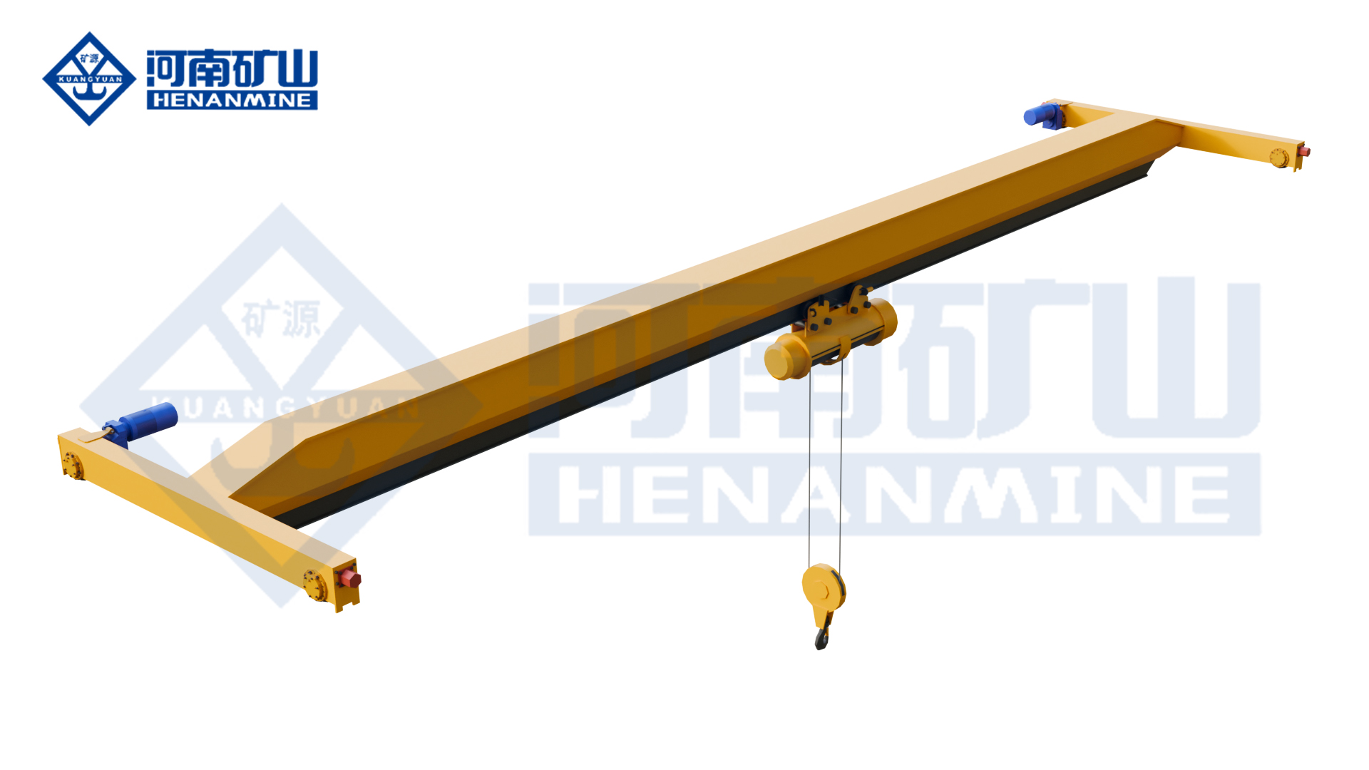
Ground-supported lifting for yards and construction.
Explore Gantry Cranes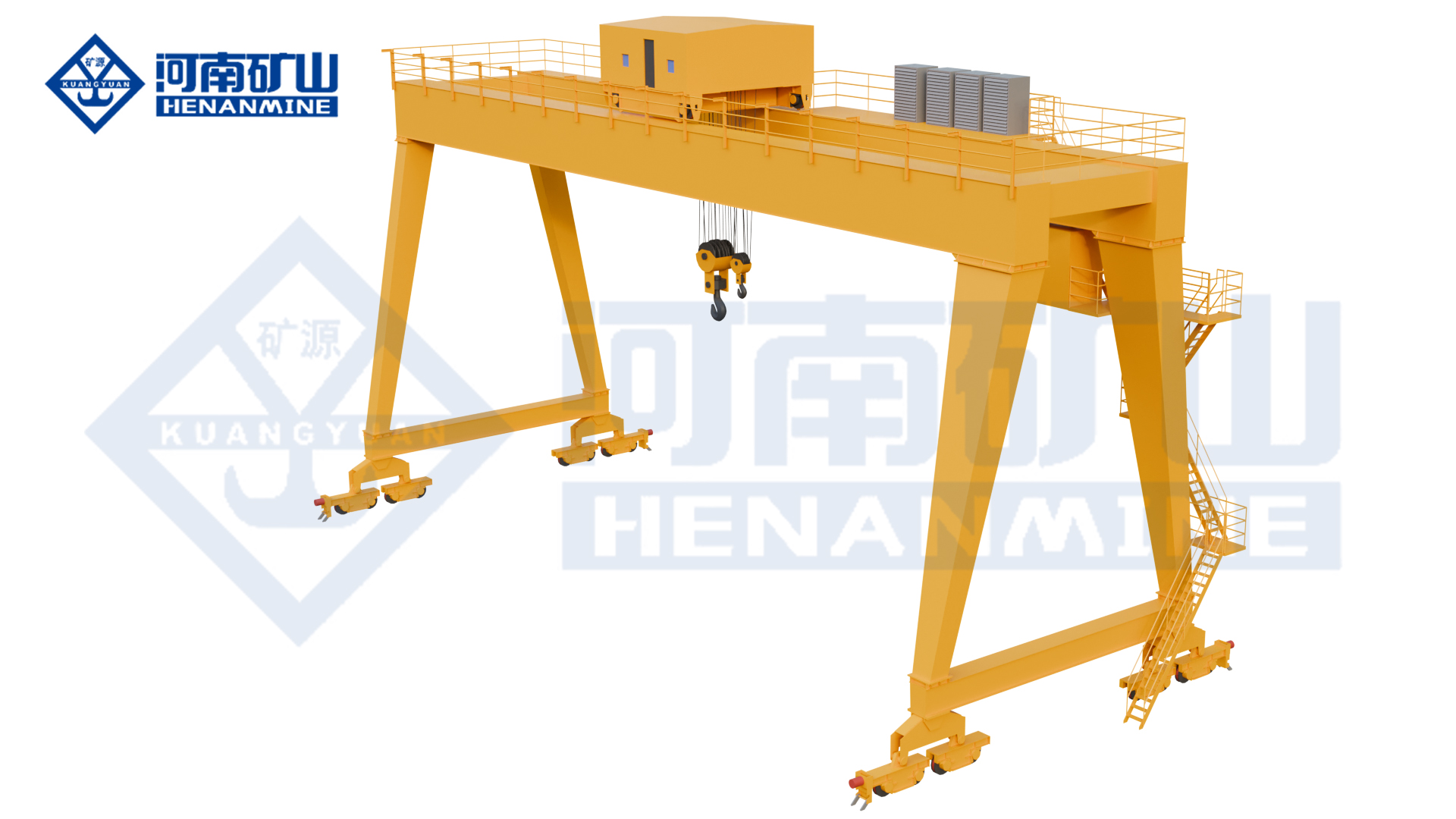
Wire rope and chain hoists for lifting points and cranes.
Explore Electric Hoists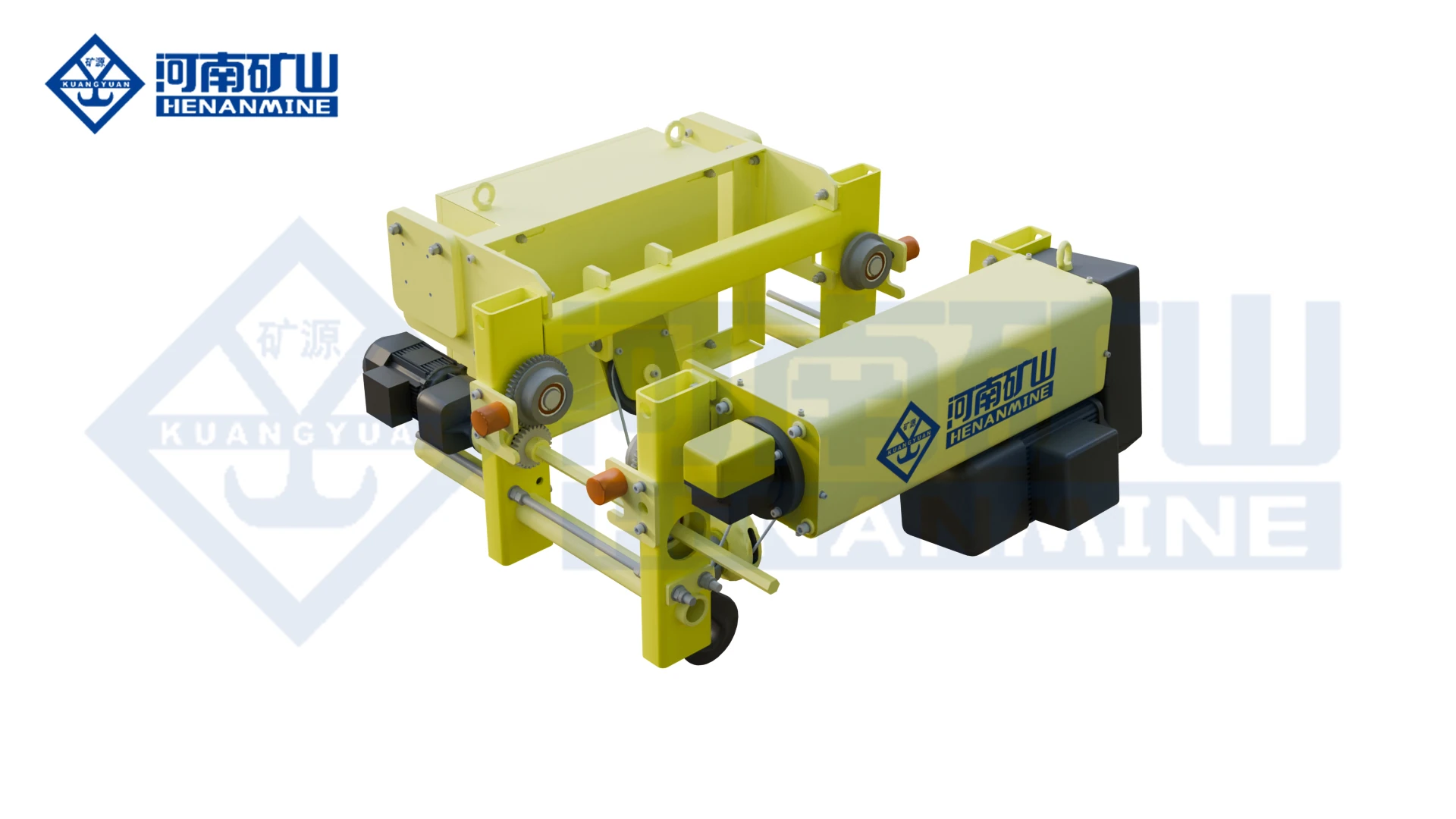
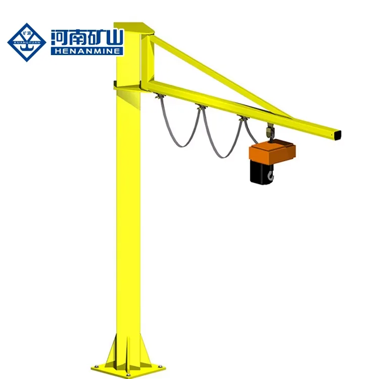
Wire rope lifting and pulling with a powered drum.
Explore Electric Winches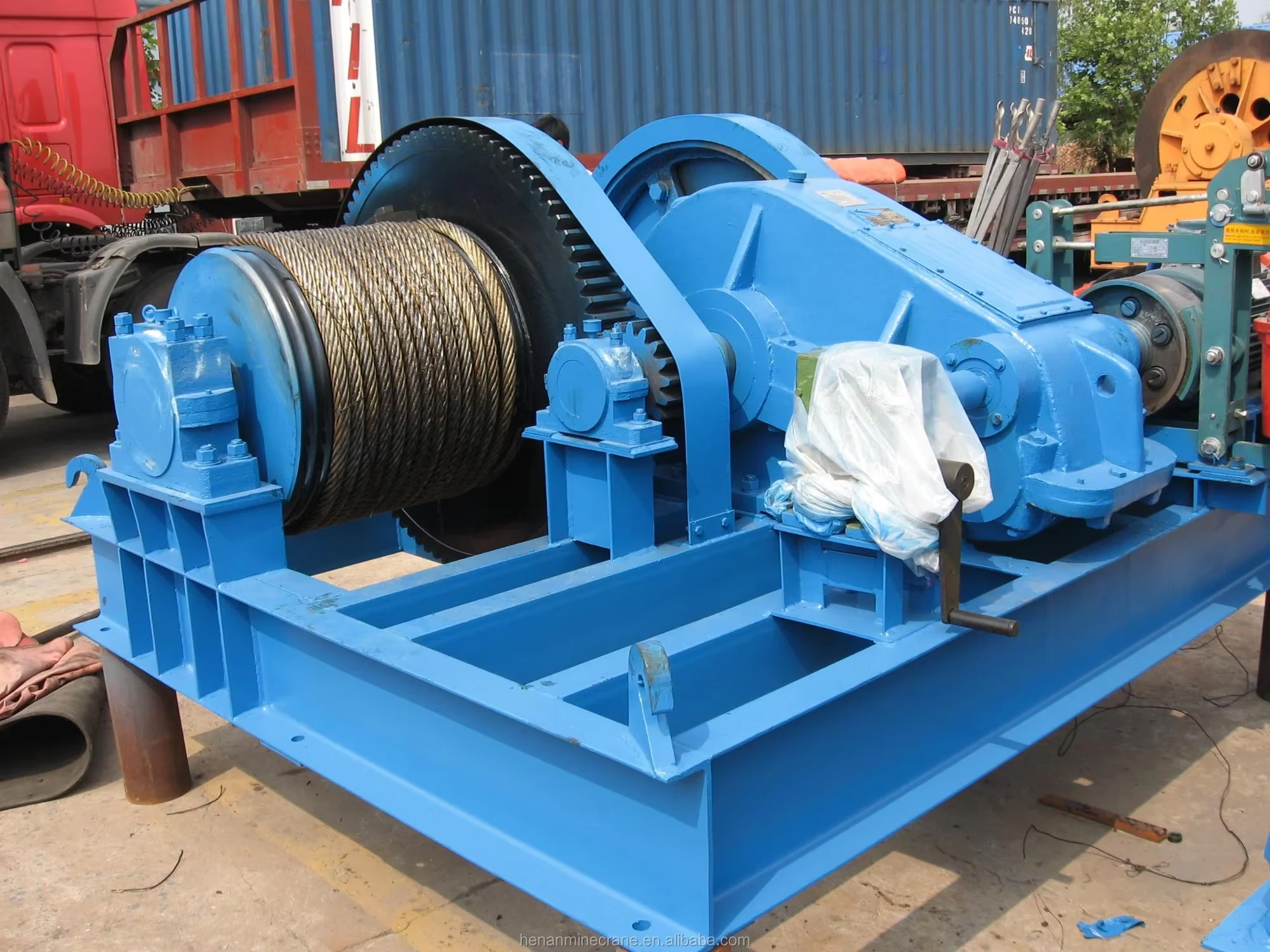
Grab buckets, magnets and hooks for your load.
Explore Lifting Attachments & Grabs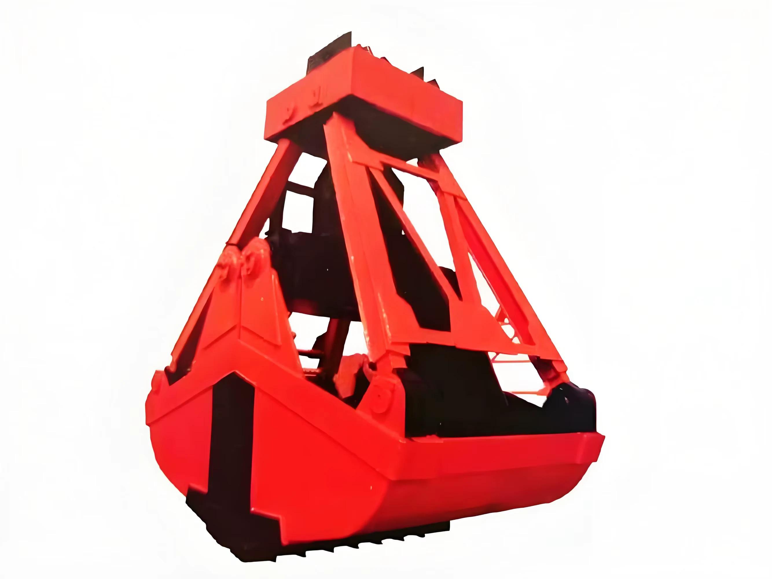
Mobile handling for containers, precast and yard loads.
Explore Rubber-Tired Gantry Cranes & Straddle Carriers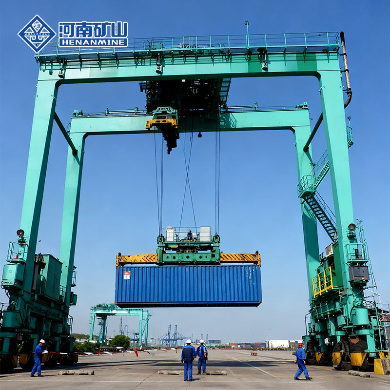
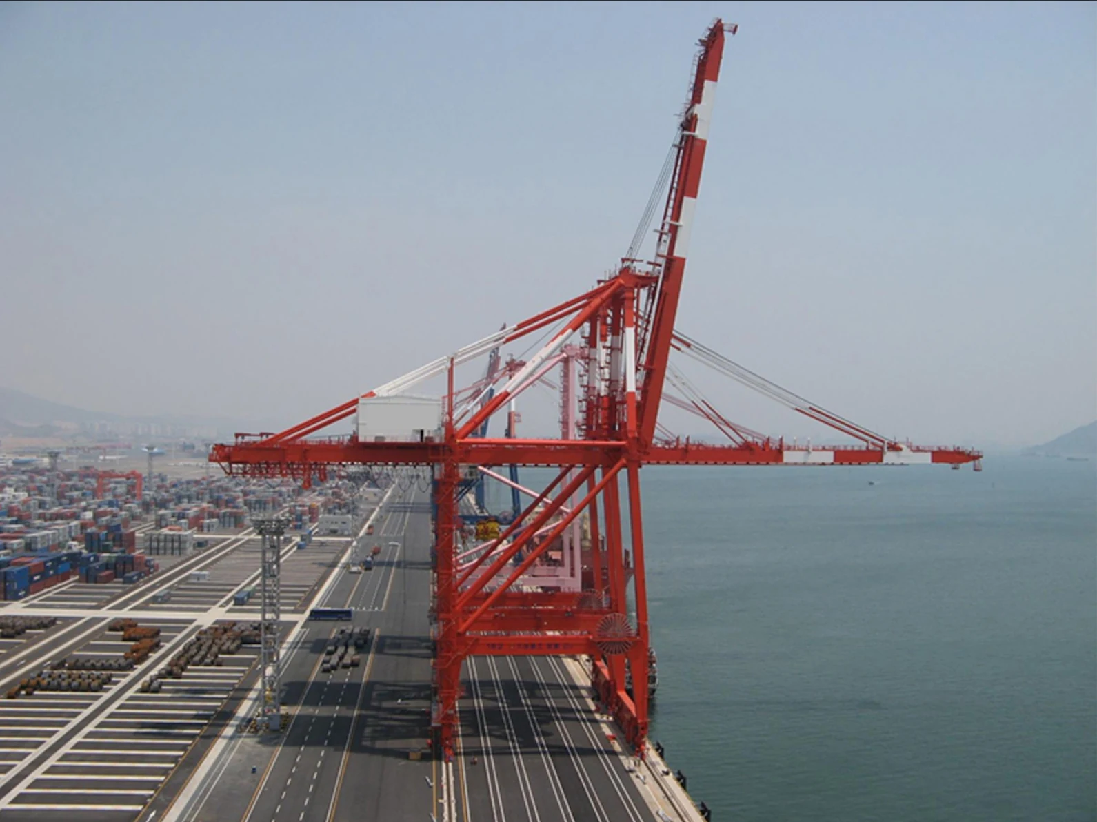
Lift and move vessels through boatyards and marinas.
Explore Marine Travel Lifts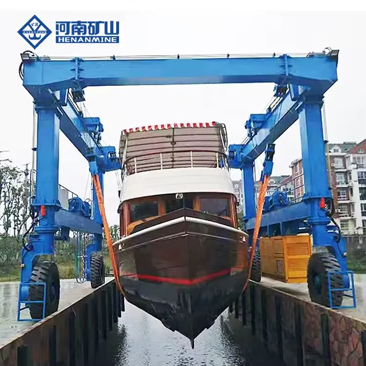
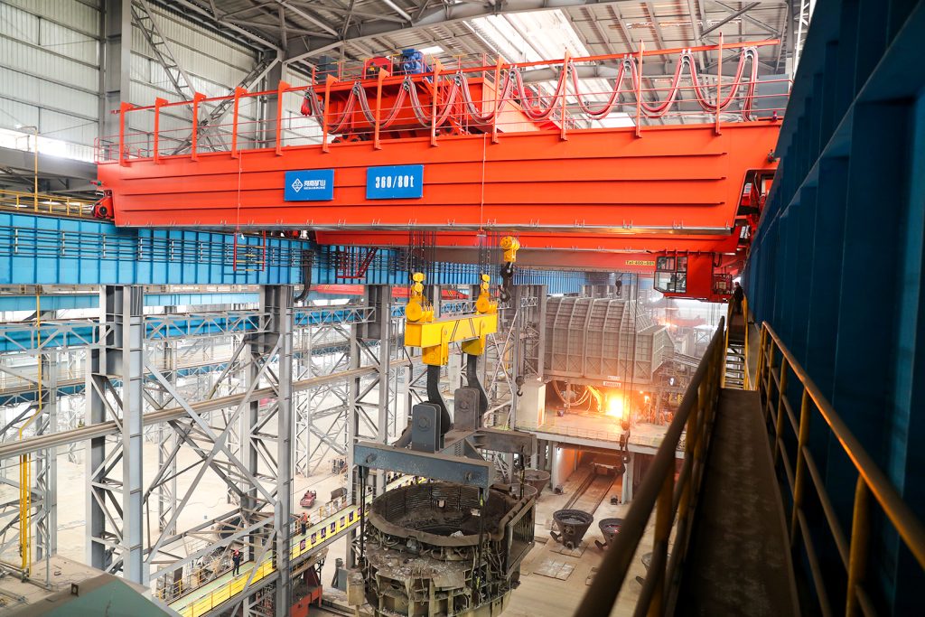
Ladle, slab, scrap and coil handling across steel production.
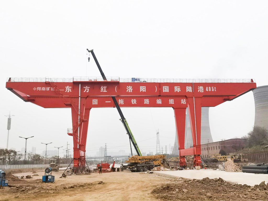
Container stacking and cargo transfers across terminals and rail.
Turbine installation, powerhouse maintenance and wind equipment assembly.
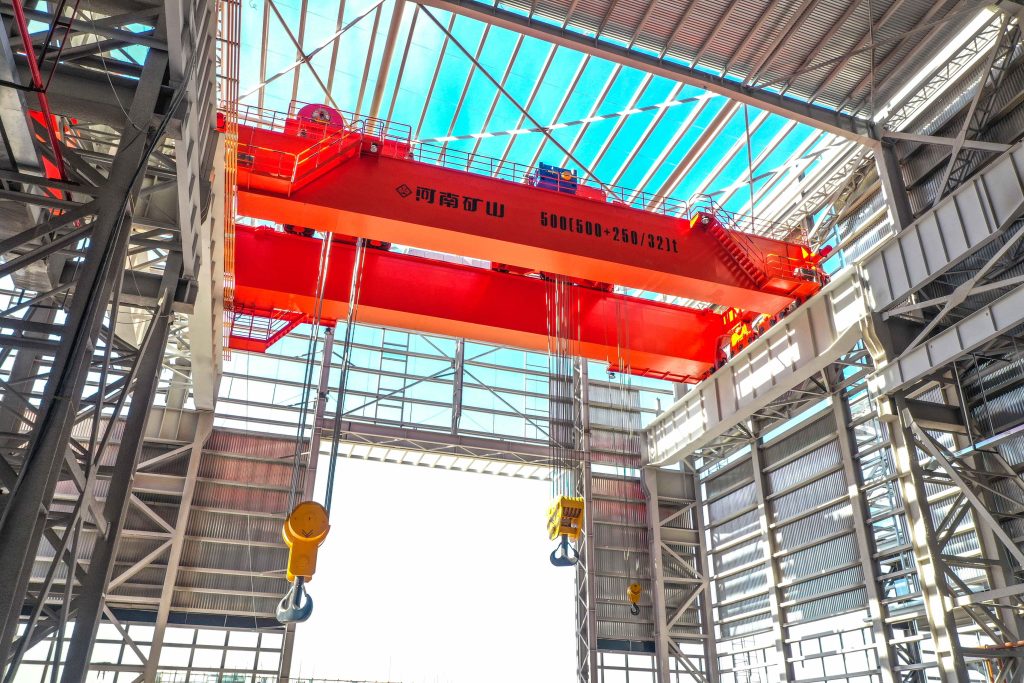
Controlled component transfer and positioning for precision assembly.
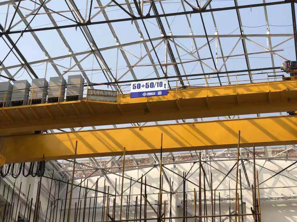
Heavy fabrication, production lifting and factory crane automation.
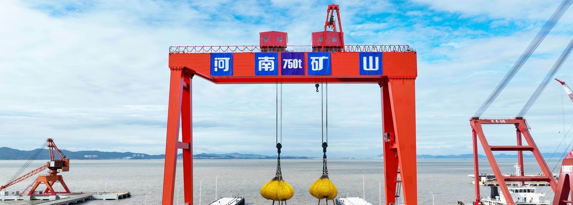
Process lifting for smelters, carbon blocks and anode materials.
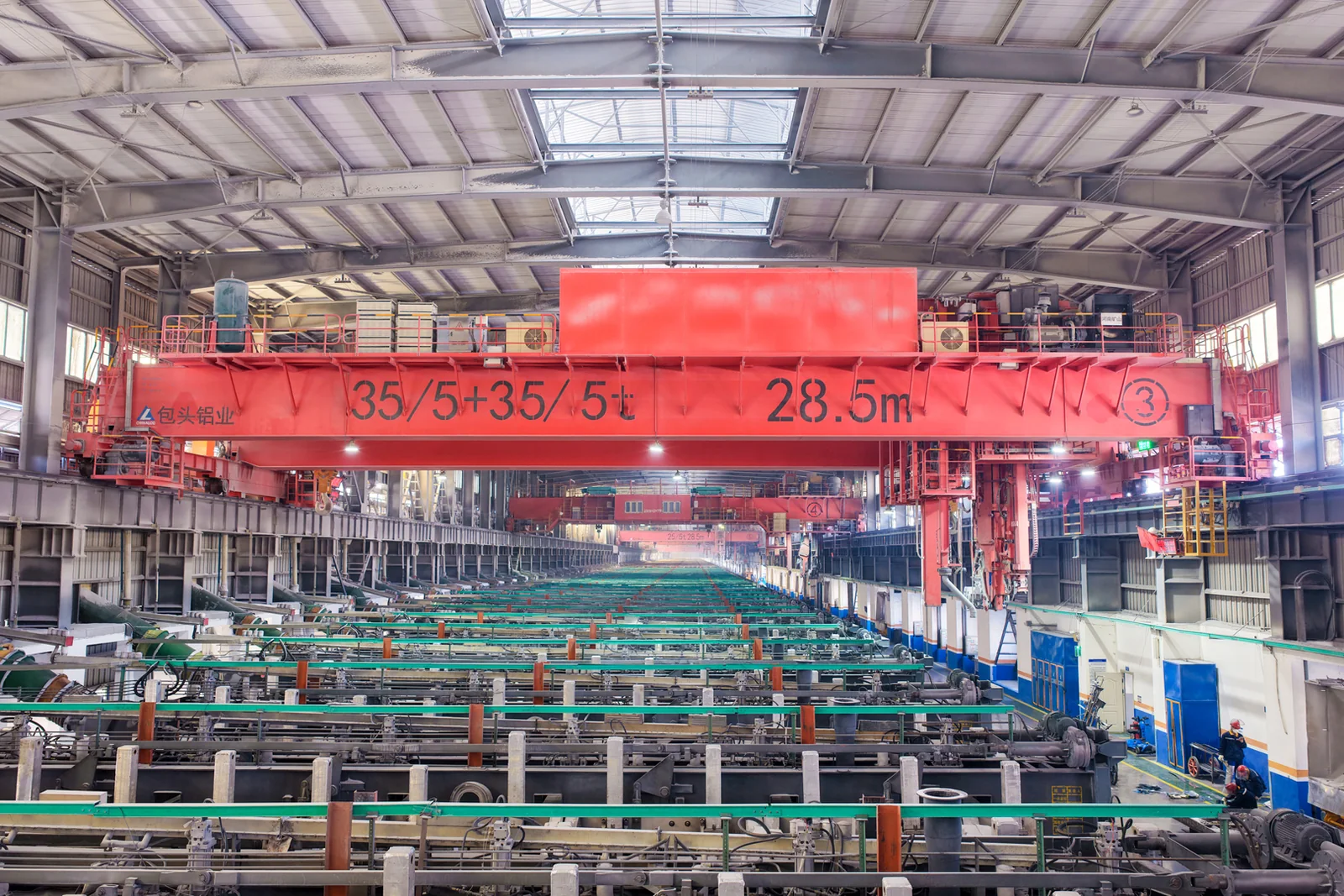
Clean lifting and classified protection for sensitive process areas.
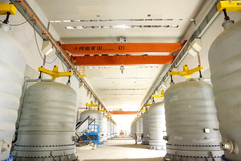
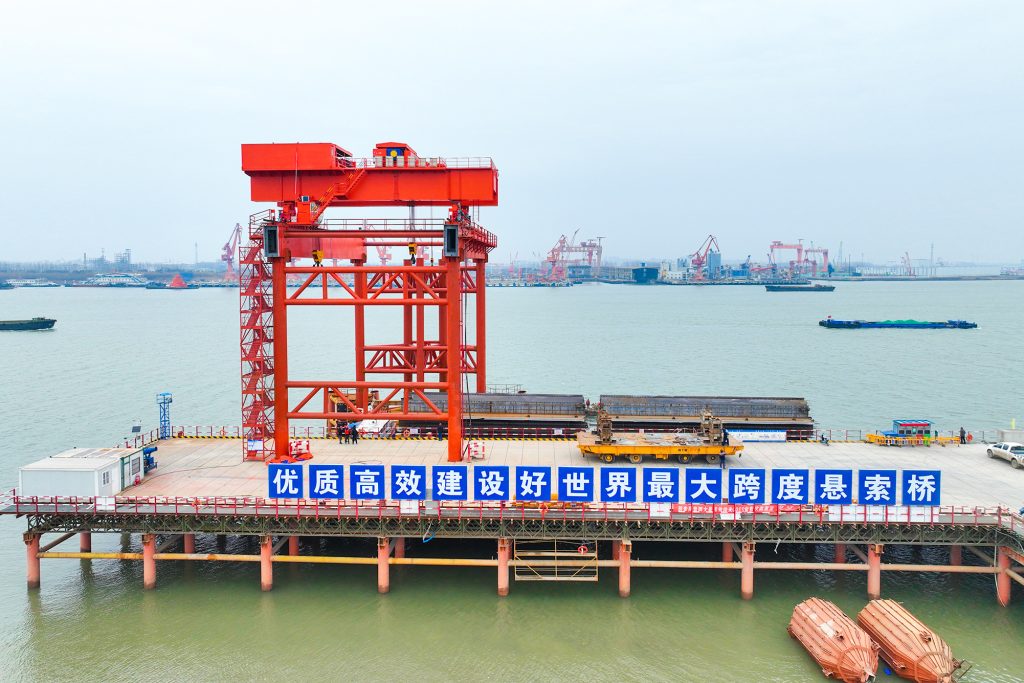
Bridge fabrication, metro construction and ship block assembly.
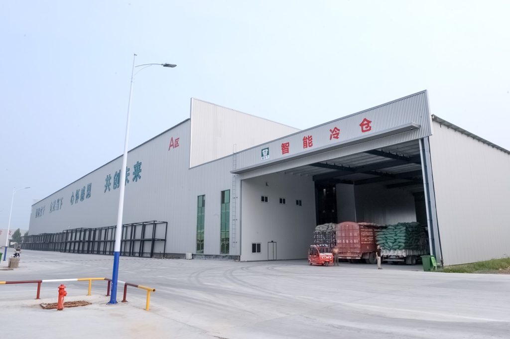
Automated storage and retrieval for plates, cables and bins.
Follow project dispatches, crane engineering and factory acceptance.
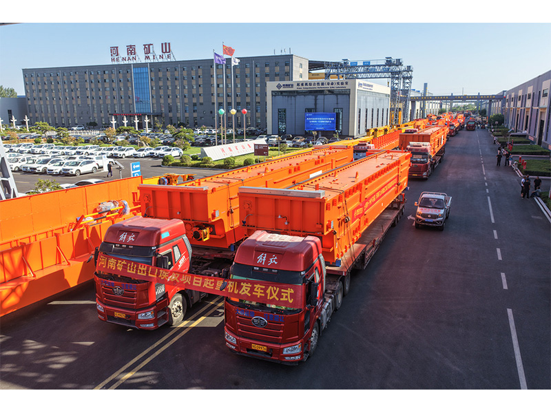
Dispatch, installation and equipment in service
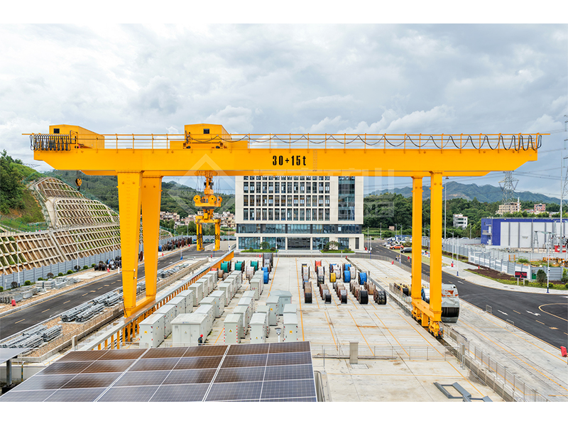
Crane configurations and handling technology
Factory inspections, acceptance and test programmes

Company developments, people and community programmes
Compare the resistance-related voltage drop of different conductor sizes and cable lengths for a stated load current.
For three-phase AC, use line-to-line voltage and line current. The tool applies the corresponding circuit multiplier.
Use one-way length and the cross-sectional area of one conductor. Set the expected conductor temperature.
Read volts and percent of supply. For AC, assess the omitted reactance and starting conditions separately.
40 A, 100 m one-way length, 16 mm² copper, 70 °C conductor temperature and 0.85 power factor.
Estimated resistive drop is about 7.593 V, or 1.898% of the 400 V supply.
Higher conductor temperature raises the assumed resistance.
Larger conductor area lowers the resistive drop at the same current and length.
AC reactance, harmonics, starting current, cable ampacity and protection coordination are outside the model.
Doubling the cable route length manually for a two-wire circuit; the formula already includes the return path.
R_conductor = ρ20[1 + α(T − 20)] L / A
DC: ΔV = 2 I R; single-phase AC: ΔV ≈ 2 I R cos φ
Balanced three-phase AC: ΔV ≈ √3 I R cos φ
It estimates one voltage-drop component. Ampacity, installation method, short-circuit withstand, protection and applicable drop limits need separate assessment.
The real cable has reactance and may have unbalanced current or other effects omitted by this resistance-only approximation.