
Use one coordinate reference
Locate every component’s centre from the same origin. Negative coordinates are allowed on the opposite side of an axis.
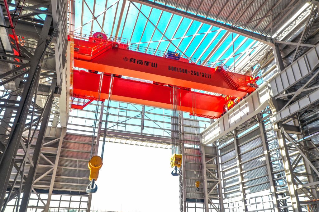
Bridge cranes for workshops and production lines.
Explore Overhead Cranes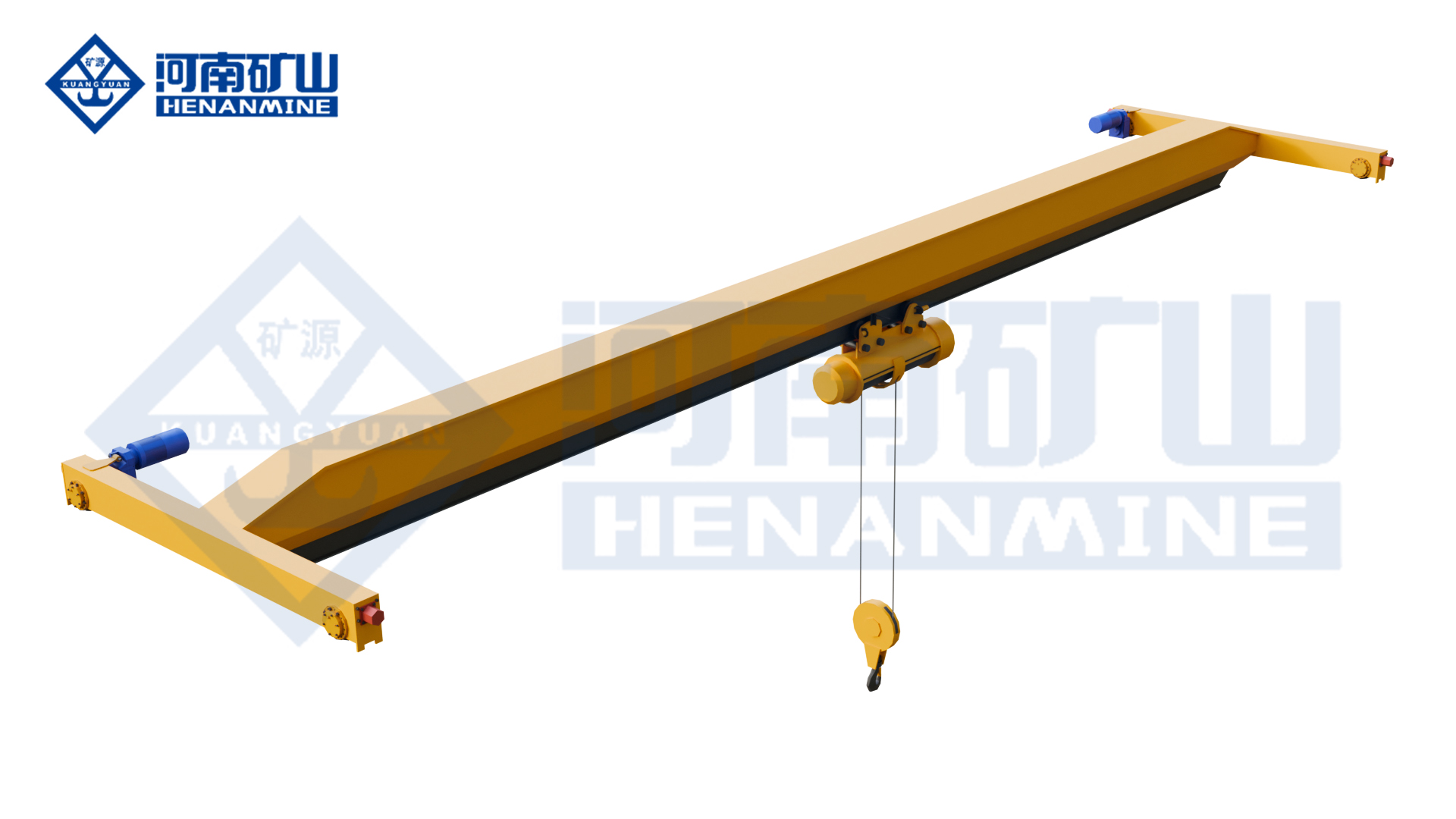
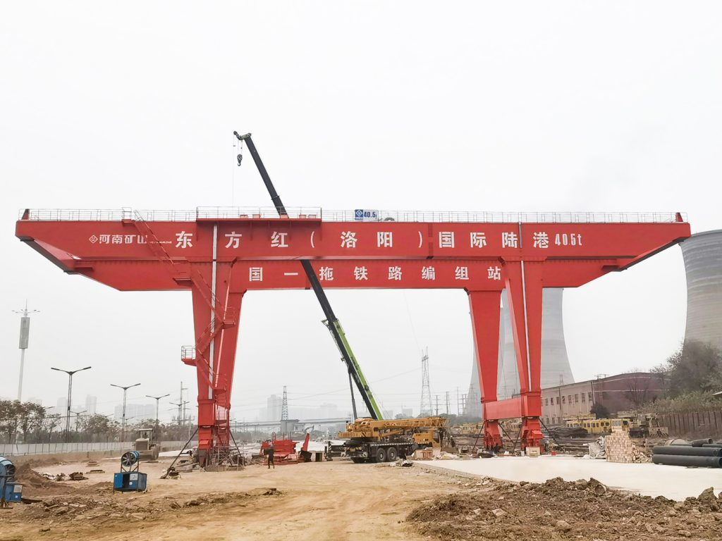
Ground-supported lifting for yards and construction.
Explore Gantry Cranes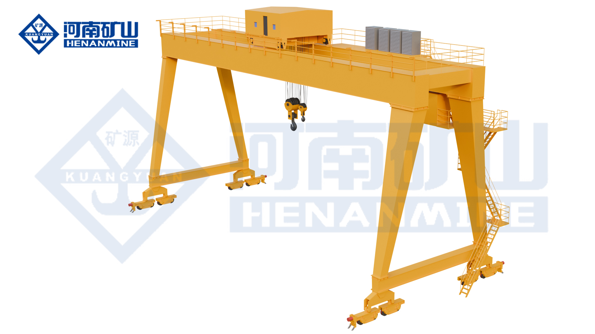
Wire rope and chain hoists for lifting points and cranes.
Explore Electric Hoists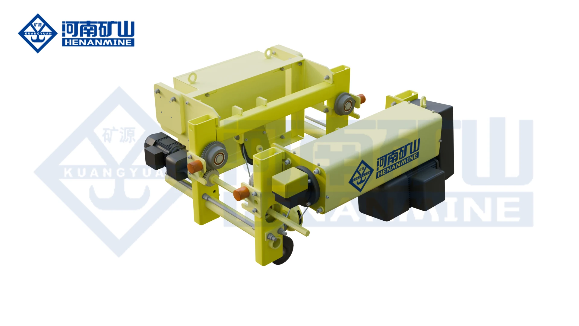
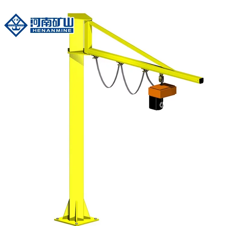
Wire rope lifting and pulling with a powered drum.
Explore Electric Winches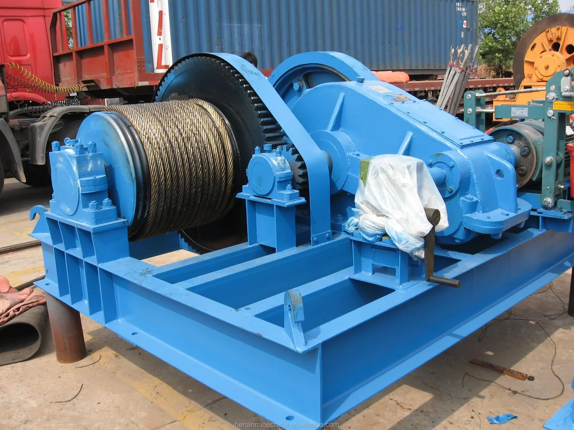
Grab buckets, magnets and hooks for your load.
Explore Lifting Attachments & Grabs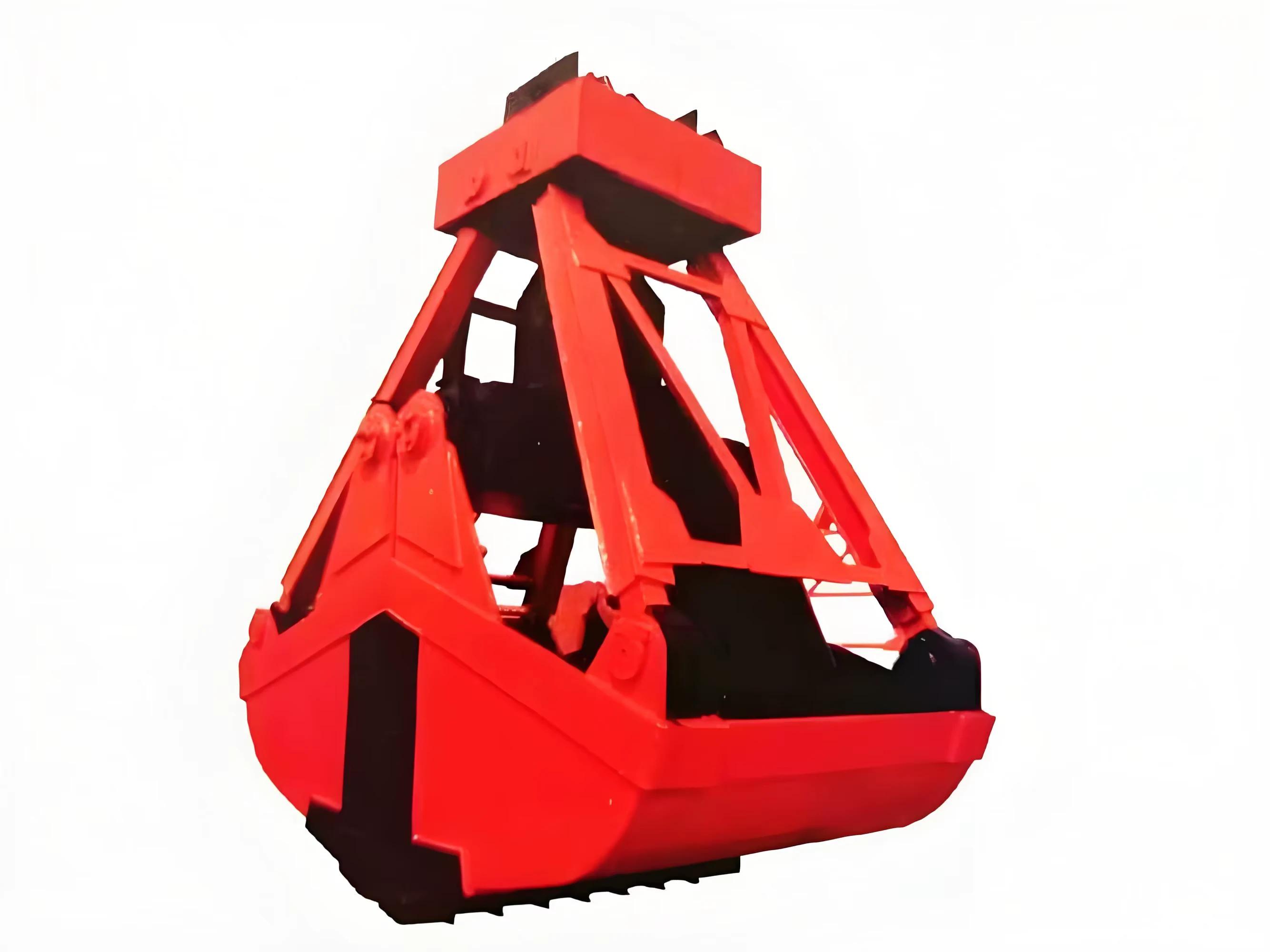
Mobile handling for containers, precast and yard loads.
Explore Rubber-Tired Gantry Cranes & Straddle Carriers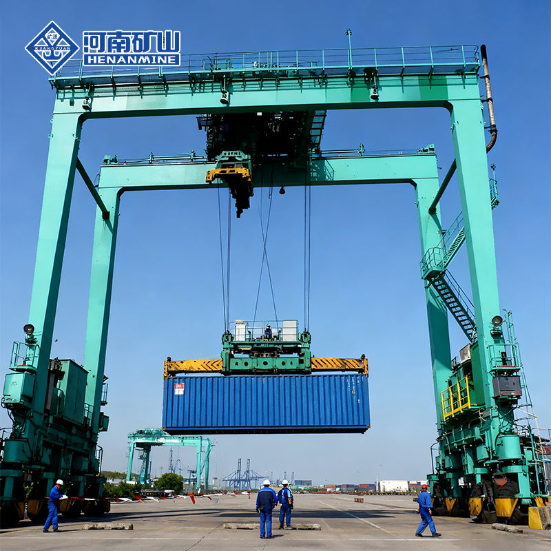
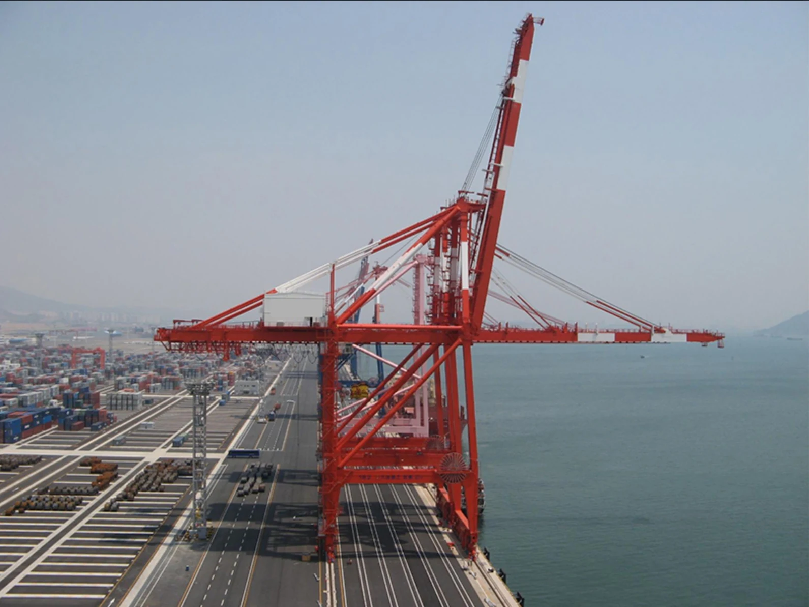
Lift and move vessels through boatyards and marinas.
Explore Marine Travel Lifts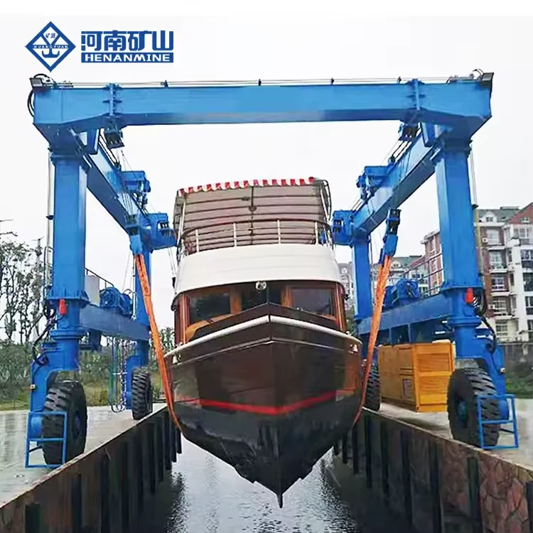
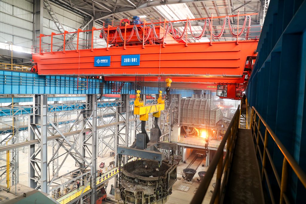
Ladle, slab, scrap and coil handling across steel production.
Container stacking and cargo transfers across terminals and rail.
Turbine installation, powerhouse maintenance and wind equipment assembly.
Controlled component transfer and positioning for precision assembly.
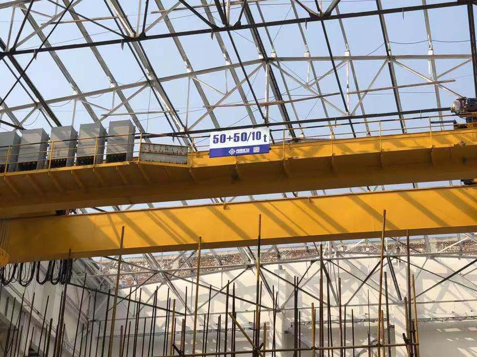
Heavy fabrication, production lifting and factory crane automation.
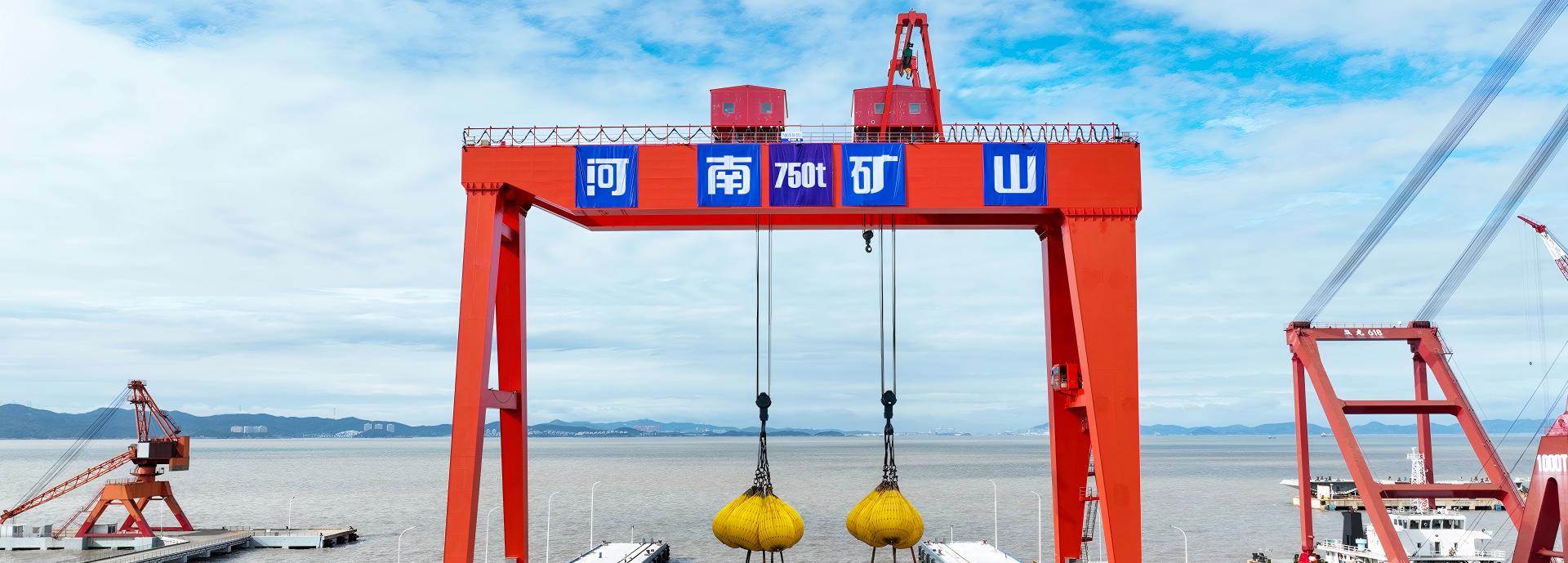
Process lifting for smelters, carbon blocks and anode materials.
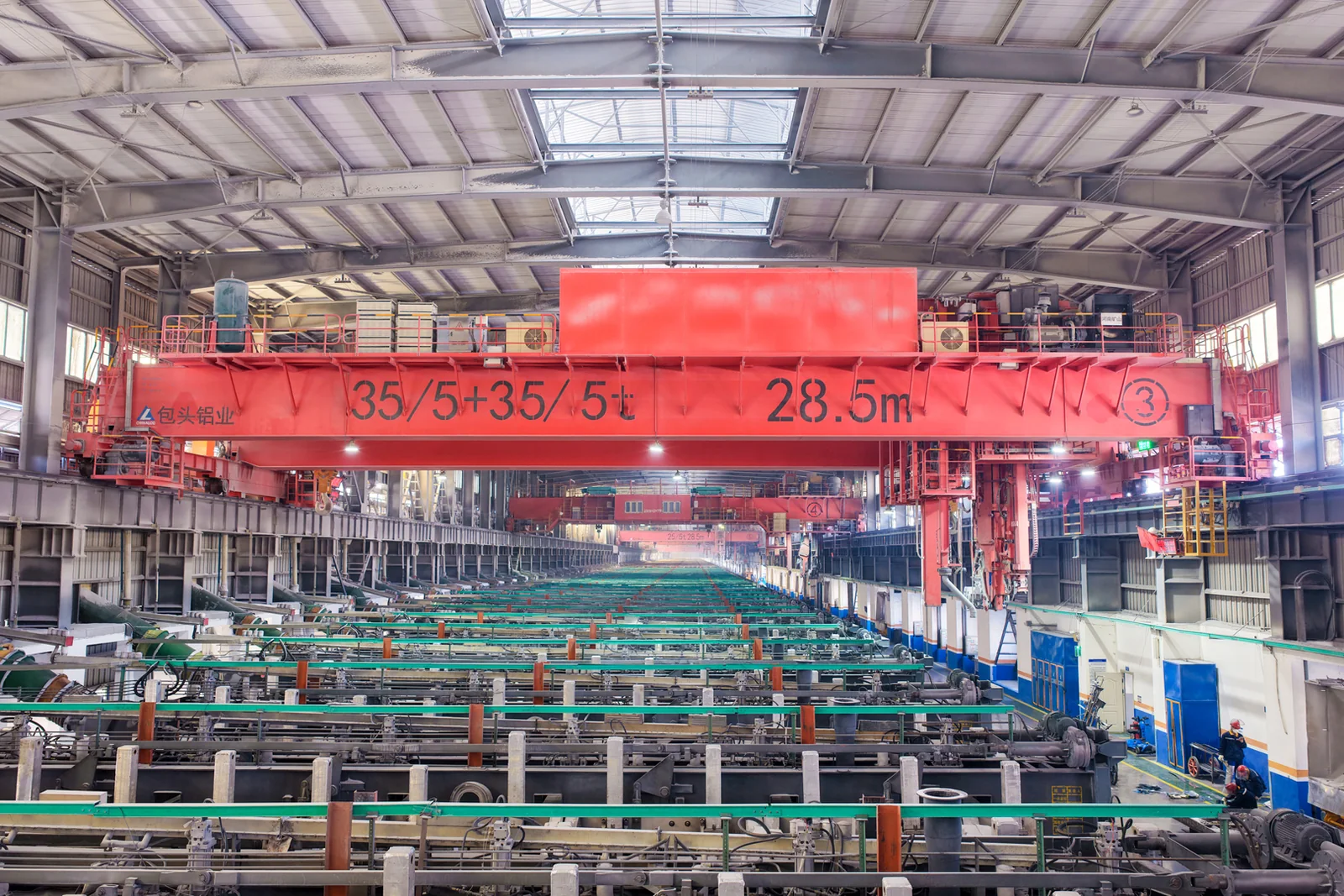
Clean lifting and classified protection for sensitive process areas.
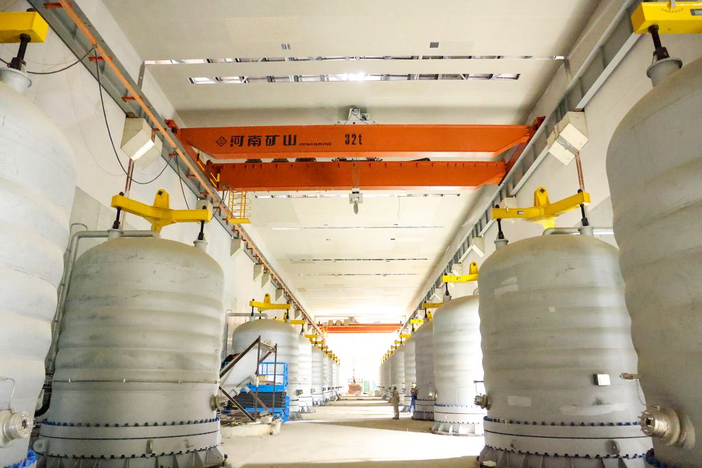
Bridge fabrication, metro construction and ship block assembly.
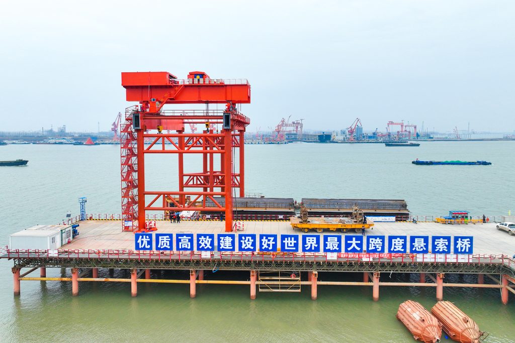
Automated storage and retrieval for plates, cables and bins.
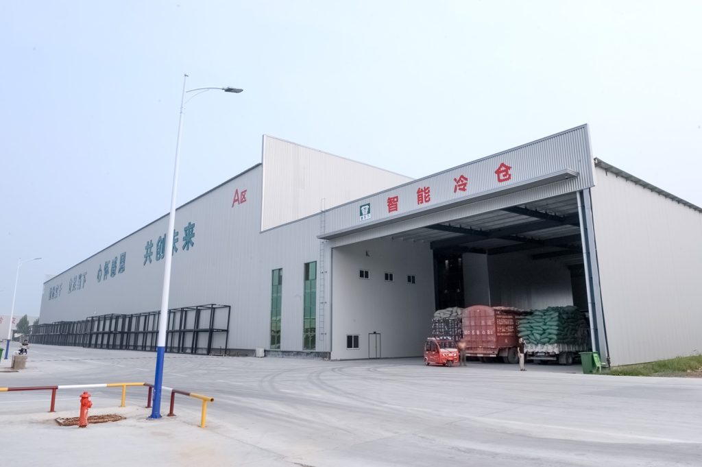
Follow project dispatches, crane engineering and factory acceptance.
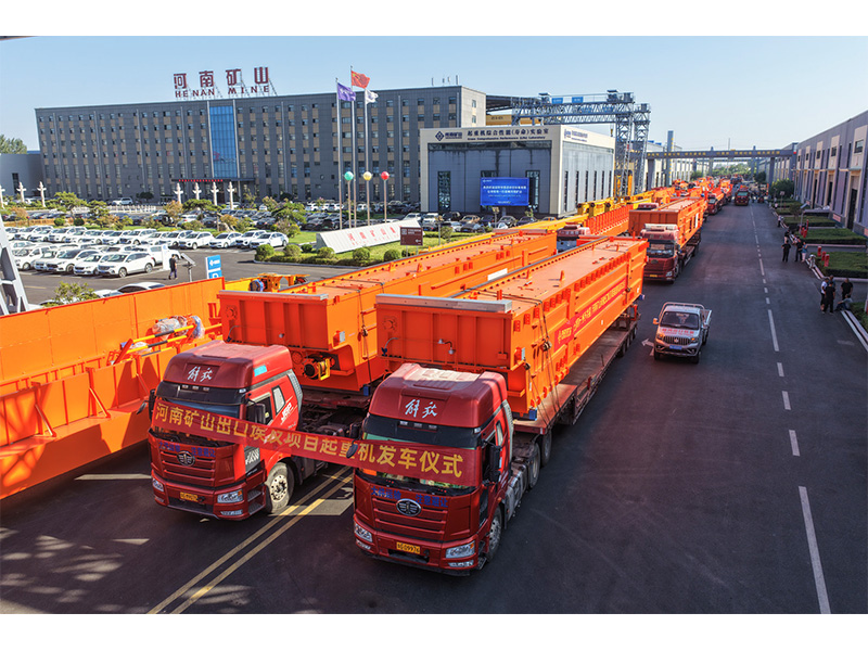
Dispatch, installation and equipment in service
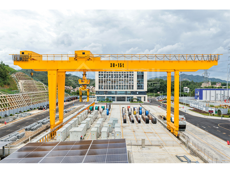
Crane configurations and handling technology
Factory inspections, acceptance and test programmes

Company developments, people and community programmes
Use this when a load consists of up to three components whose individual masses and centres of gravity are known. It locates their combined centre in a horizontal coordinate system.
Locate every component’s centre from the same origin. Negative coordinates are allowed on the opposite side of an axis.
Enter each component’s mass and x/y coordinates. Set an unused mass group to zero.
Plot the resulting x and y on the same drawing. Use the combined mass to verify that no component has been omitted.
Group 1: 1,000 kg at (0, 0) m; group 2: 2,000 kg at (2, 0) m; group 3: 0 kg.
Combined mass is 3,000 kg. The combined centre of gravity is at x = 1.33333 m and y = 0 m, nearer the heavier component.
The x and y results are coordinates from your chosen origin, not distances from the outer edge of the complete load unless you chose that edge as zero.
A heavier component pulls the combined centre of gravity toward its own centre.
The result is a two-dimensional mass balance; it does not by itself establish stable lifting points or load orientation.
Using each component’s outside corner instead of its own centre of gravity, or measuring different groups from different origins.
xCG = Σ(m × x) / Σm
yCG = Σ(m × y) / Σm
Combine two or more components into a subgroup using their calculated total mass and centre, then use that subgroup as one of the three groups.
No. This form calculates x and y in your selected horizontal plane; it does not model the vertical coordinate or overturning stability.