Skip to content
Henan mine crane co., ltd. Get a project quote
Henan Mine Crane · Workshop and process lifting

Double Girder Overhead Cranes

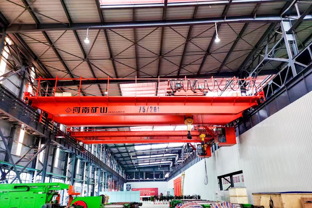
Double girder overhead cranes, also called double girder EOT cranes or bridge cranes, use two main girders to support a travelling lifting system. Compare 39 model families for workshop components, long loads, steel stock, bulk materials and process handling. Choose the load and lifting task first, then match the span, useful hook height and working duty.

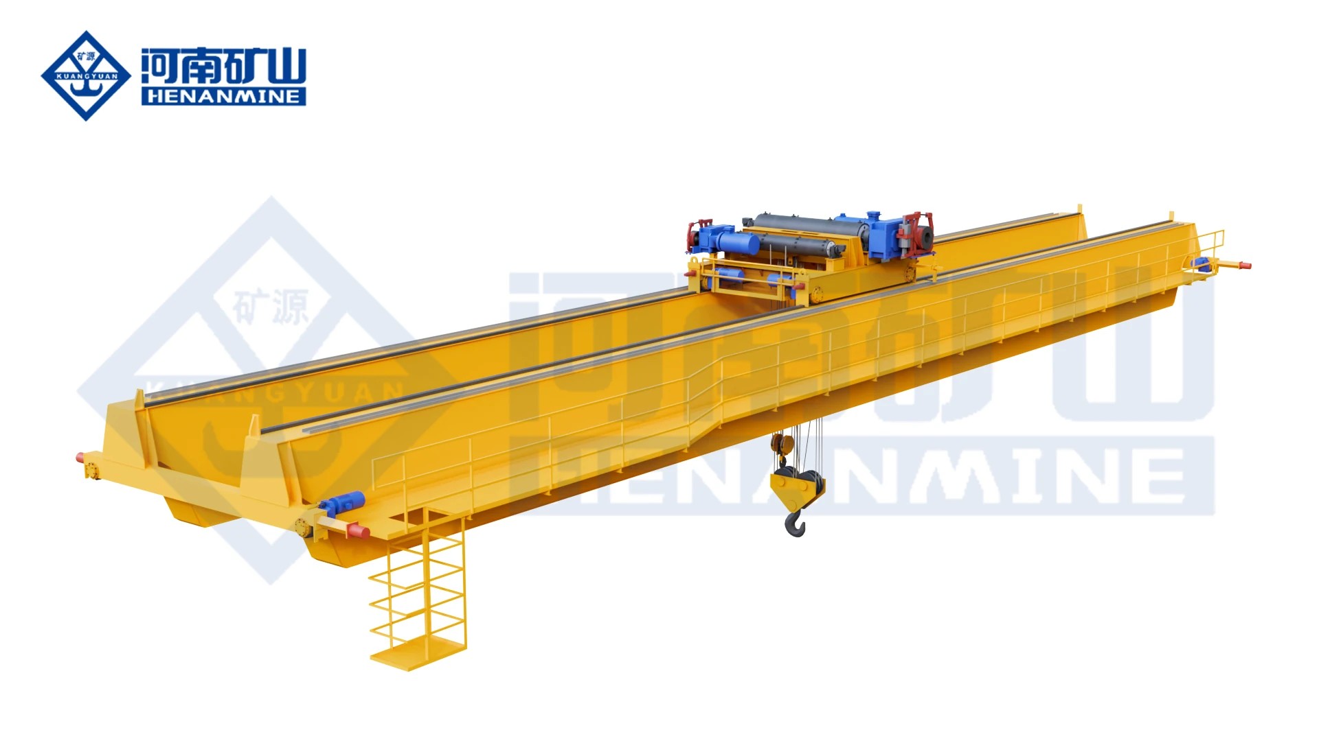
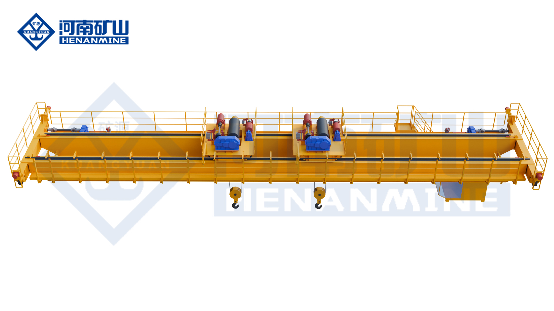
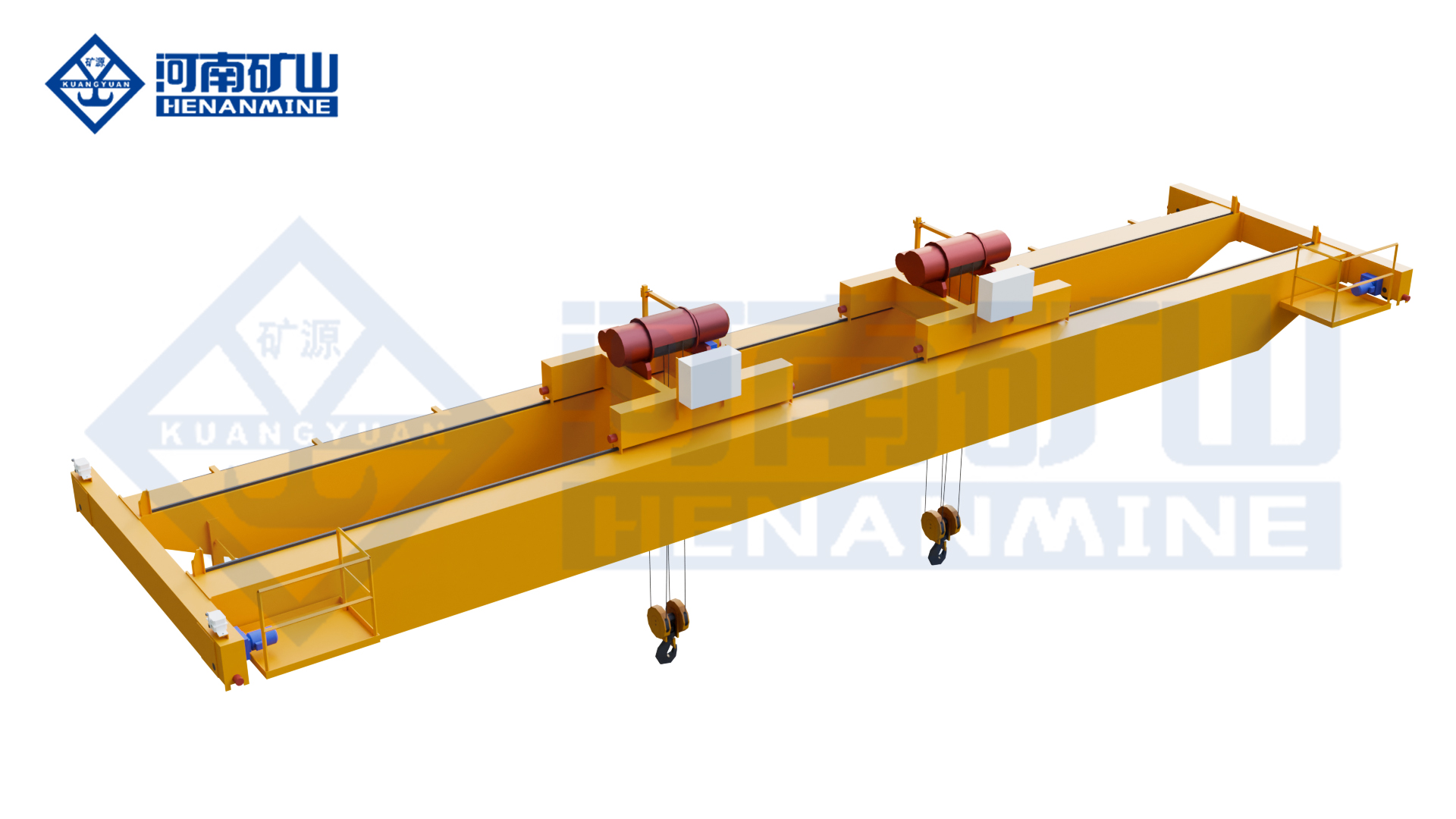
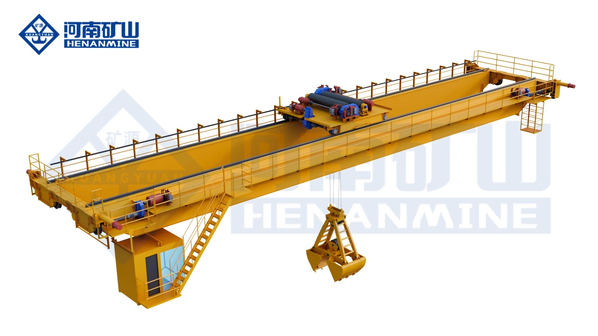
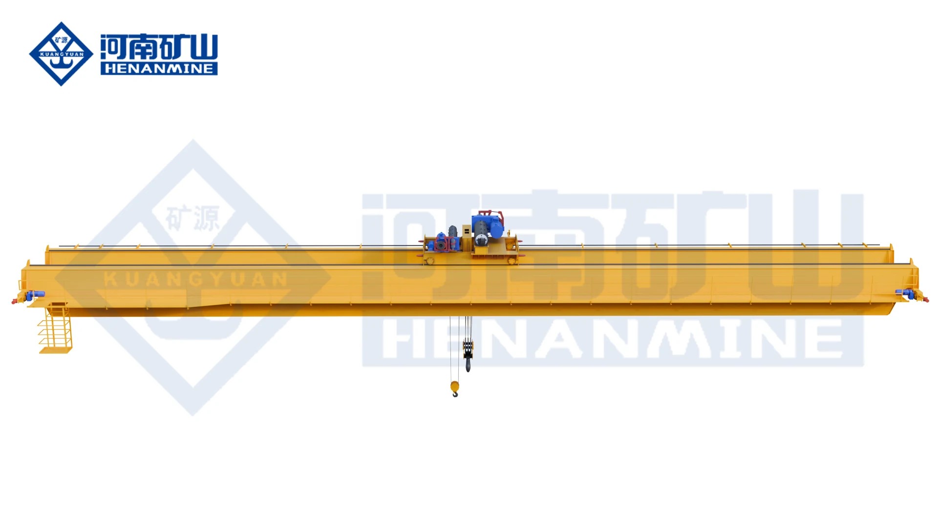
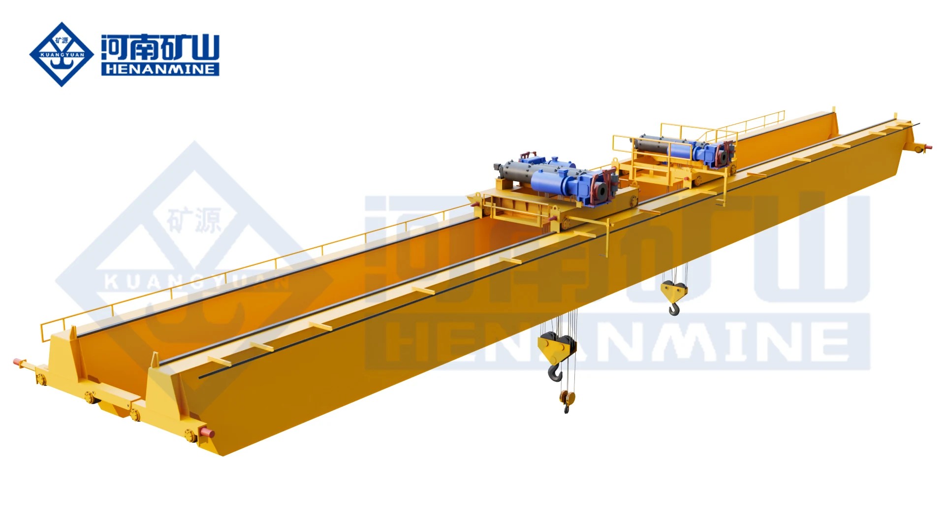
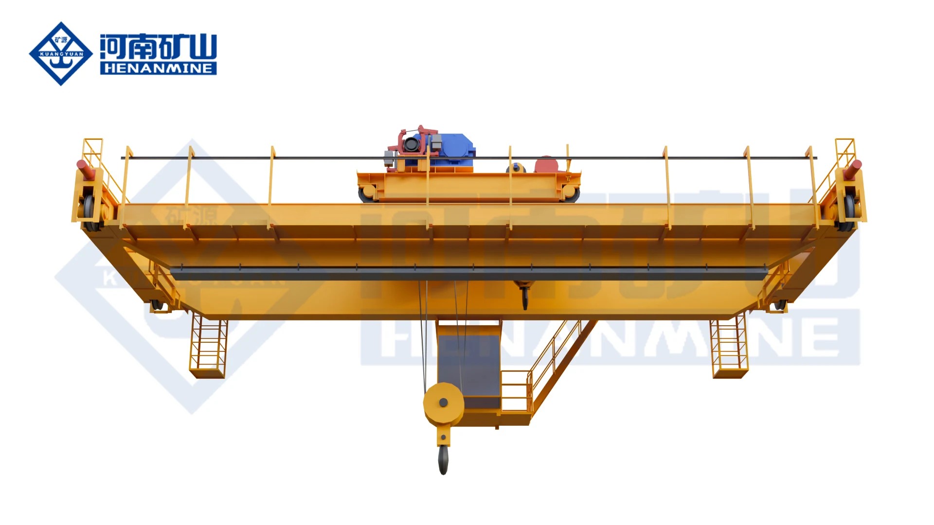
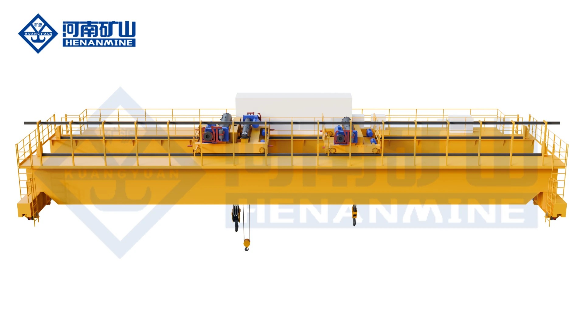
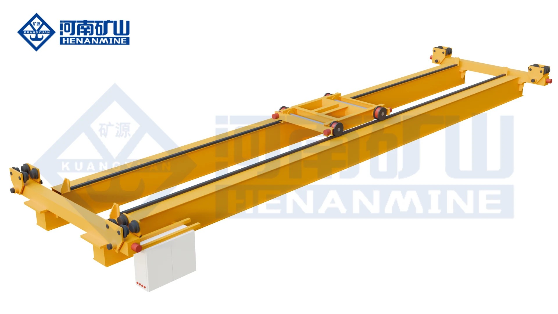
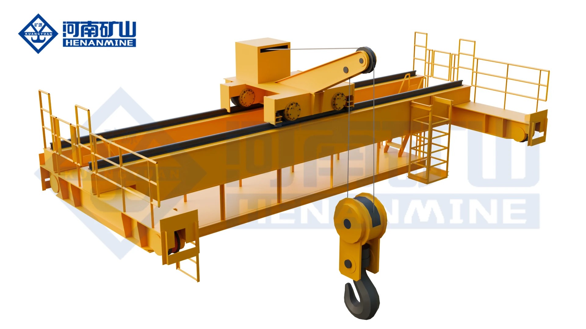
QD double-girder hook crane with winch trolley and service walkway; manufacturer rendering

Hook & multi-trolley cranes

Compare winch-trolley hook cranes, manual operation and two- or three-trolley layouts for components, long loads and paper-machine handling.

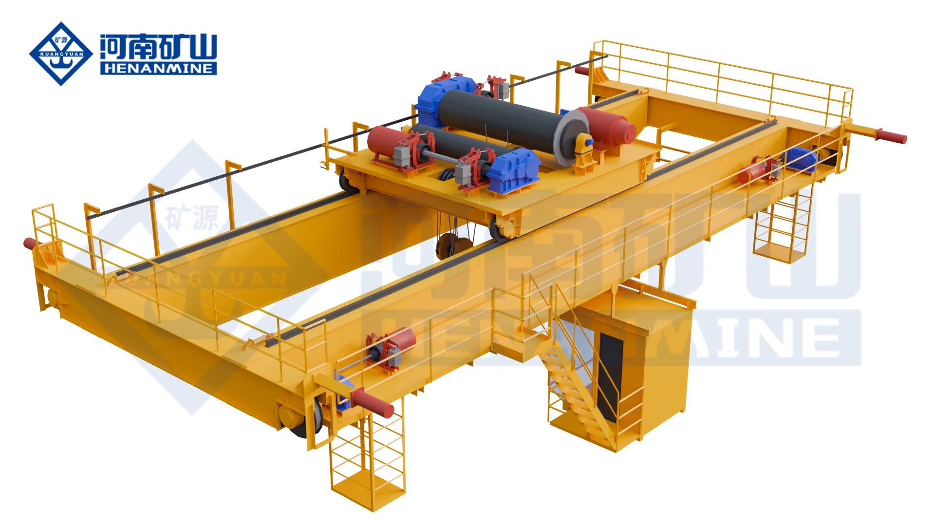
QD double-girder hook crane with winch trolley and service walkway
QD

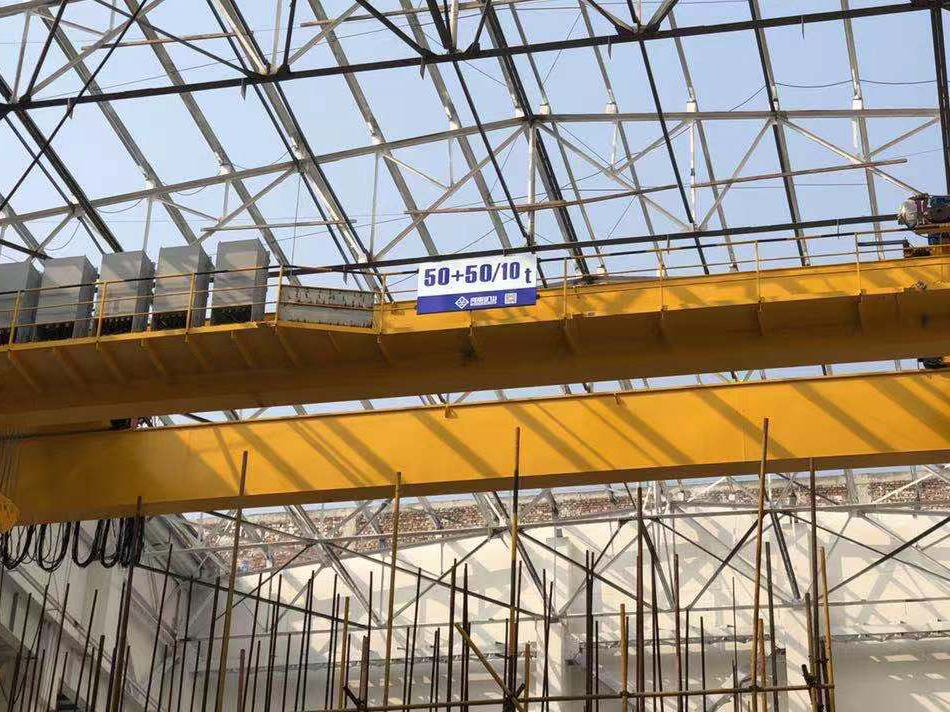
Double Girder Hook Overhead Crane (QD)

Handle workshop components and fabricated loads with a QD winch-trolley bridge crane. Select single or main/auxiliary hooks for the complete suspended load.

Capacity5 / 10 / 16/3.2 / 20/5 / 32/5 / 50/10 t; larger engineered options to 450/80 t
Span5–50 t: 10.5–31.5 m; larger cranes use capacity-specific spans
Working classA5–A6 standard selections; slow-speed A3 options
All specifications
Model QD
Rated capacity 5 / 10 / 16/3.2 / 20/5 / 32/5 / 50/10 t; larger engineered options to 450/80 t
Span 5–50 t: 10.5–31.5 m; larger cranes use capacity-specific spans
Lifting height 5/10 t: 16 m; 16/3.2 t: 16/18 m; 20/5 t: 12/14 m; 32/5 t: 16/18 m; 50/10 t: 12/16 m
Working duty 5–50/10 t standard: A5 / A6; slow-speed versions: A3; 400/80–450/80 t: A1–A3
Hoisting speed 5 t A5: 11.3 m/min; 16/3.2 t A5: 7.9/14.6 m/min
Trolley / bridge travel 5 t A5, 19.5 m span: trolley 37.2 / bridge 89.8 m/min
Lifting arrangement Winch trolley; hook or main/auxiliary hooks
Control Cabin, pendant or radio control to the ordered arrangement
Power supply 380 V / 50 Hz, three-phase; destination supply by specification
Operating environment General workshops and warehouses; outdoor package available
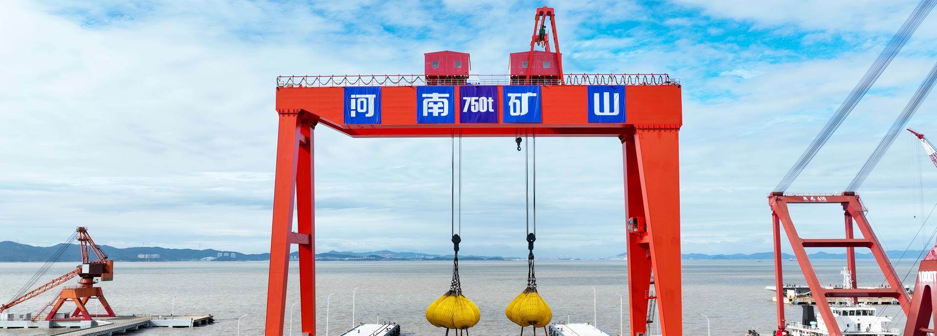
Heavy-load configurations 75/20 / 100/20 / 125/32 / 160/50 / 200/50 / 250/50 / 300/40 / 350/75 / 400/80 / 450/80 t
Heavy-load geometry 300/40 t: 17 m span; 350/75 t: 22 m; 400/80 t: 21 m; 450/80 t: 20.8 m
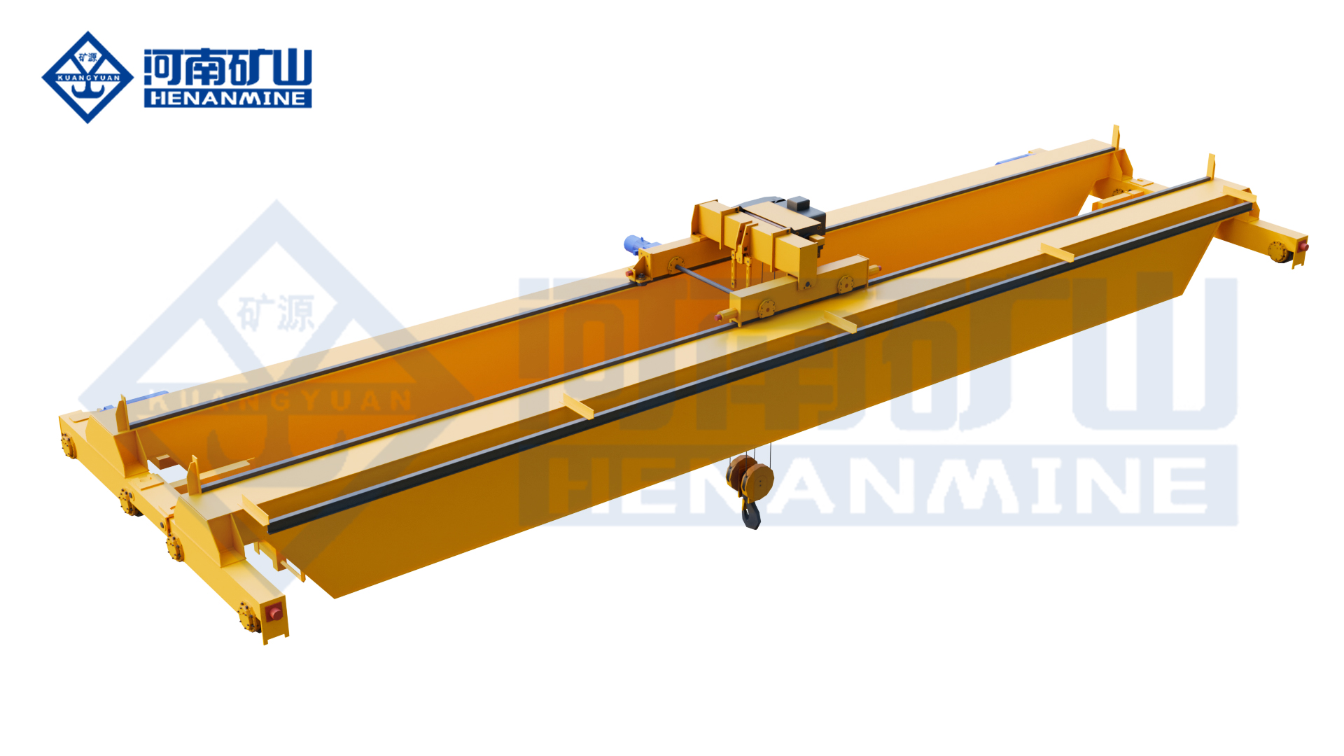
SQ hand-driven double-girder crane front elevation with manual trolley, hook and operating chains
SQ

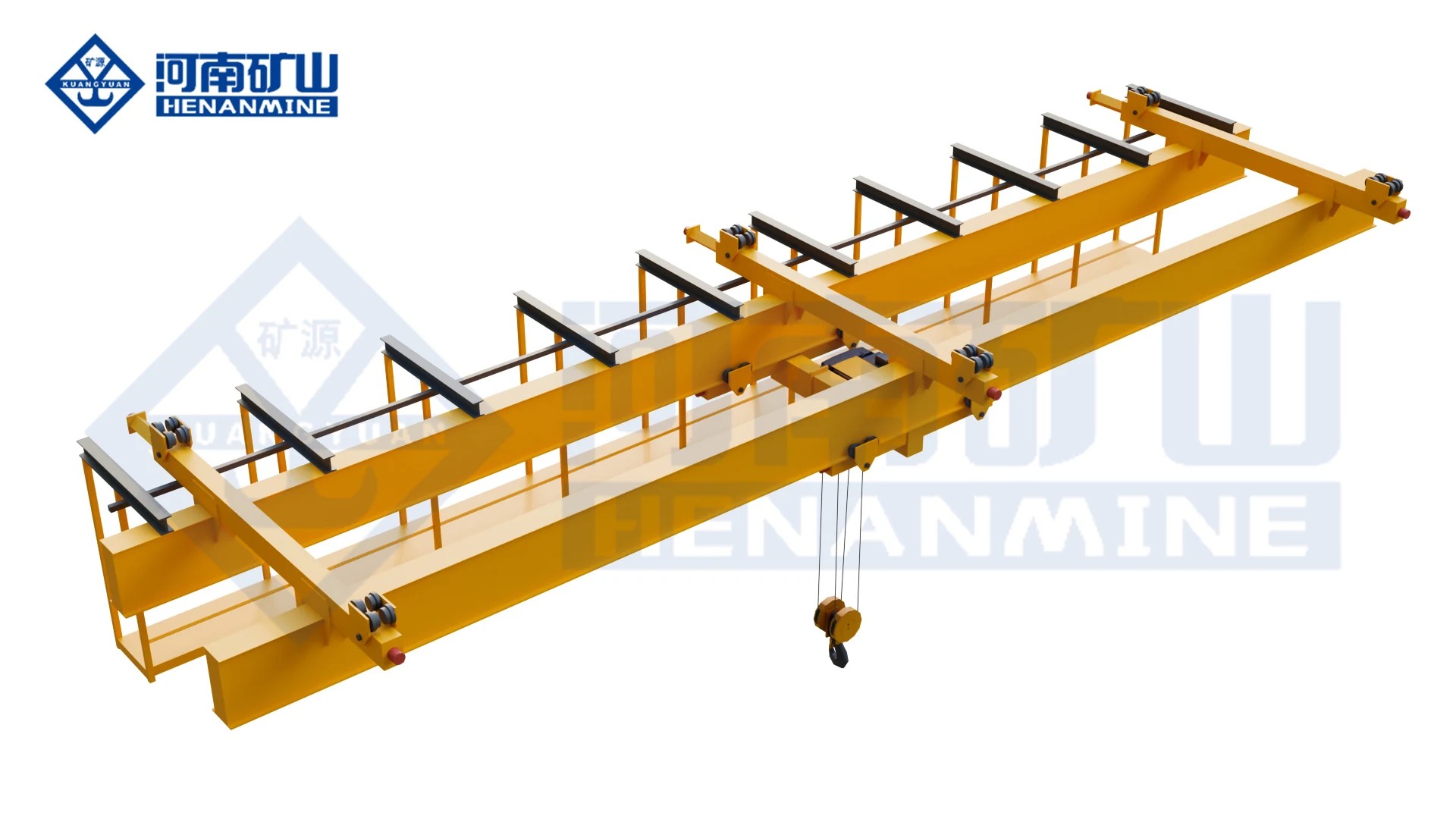
Manual Double Girder Overhead Crane (SQ)

Lift occasional maintenance and storage loads with a manually operated double-girder bridge where powered travel is unnecessary.

Capacity5 / 10 / 16 / 20 t
Span10–17 m
Working classOccasional manual handling; selected for lifting frequency and operating effort
All specifications
Model SQ
Rated capacity 5 / 10 / 16 / 20 t
Span 10–17 m
Lifting height 10 / 16 m configurations
Working duty Occasional manual handling; selected for lifting frequency and operating effort
Hoisting speed Hand-operated lifting; speed depends on the selected mechanism and operator
Trolley / bridge travel Hand-driven; travel distance and manual effort govern selection
Lifting arrangement Manual lifting mechanism and hook trolley on a double-girder bridge
Control Hand-chain operation for lifting, trolley and bridge travel
Power supply Not required for basic manual operation
Operating environment Warehouses, workshops and equipment-maintenance bays
10 t selection example 14 m span; lifting height 10 or 16 m; bridge wheel load 62.3 kN
Rail width, 10 t example 60 / 70 mm according to the selected runway arrangement
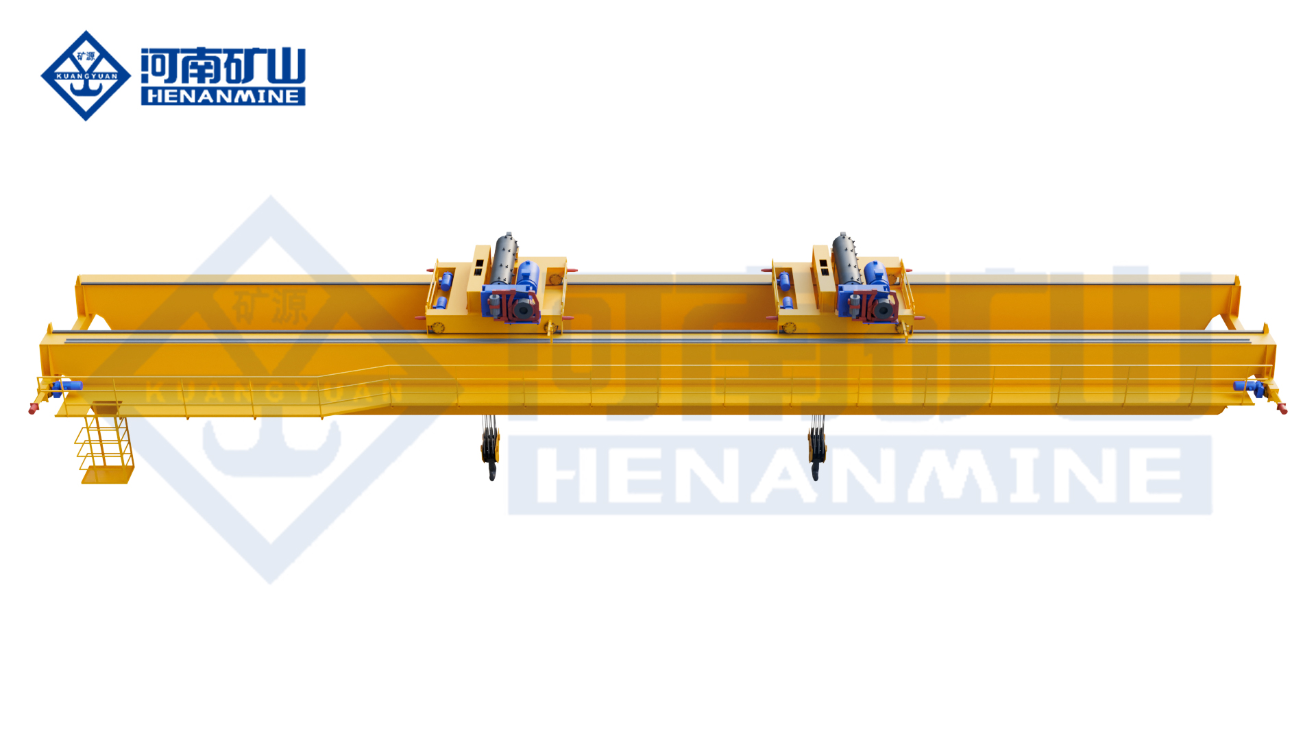
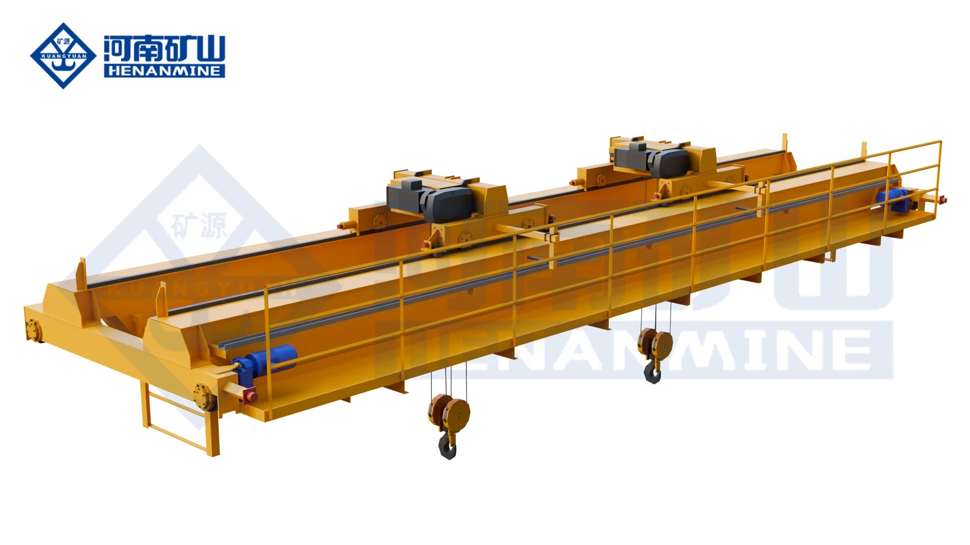
KSQ new-design winch-trolley hook crane, manufacturer view 1
KSQ

Modular Double Girder Overhead Crane (KSQ)

Position workshop components with a modular KSQ winch-trolley bridge and controlled travel matched to the handling cycle.

CapacityCustom rating for workpiece plus lifting gear
SpanCustom rail-centre span and runway length
Working classSelected for load spectrum and lifts per shift
All specifications
Model KSQ
Rated capacity Custom rating for workpiece plus lifting gear
Span Custom rail-centre span and runway length
Lifting height Custom upper/lower hook positions
Working duty Selected for load spectrum and lifts per shift
Hoisting speed Stepless lifting with low-speed positioning
Trolley / bridge travel VFD travel; selected normal and positioning speeds
Lifting arrangement Main hook; Single trolley
Control PLC/VFD; electronic anti-sway and positioning options
Power supply Three-phase supply matched to destination voltage and frequency
Operating environment Industrial service package matched to site conditions
Structure Compact modular bridge and trolley arrangement
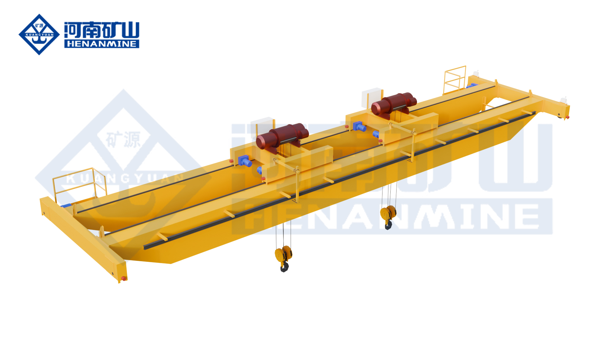
QE double-trolley hook crane, manufacturer view 1
QE

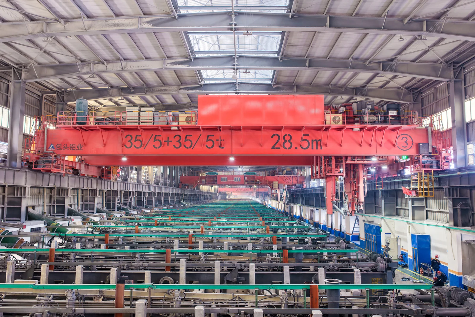
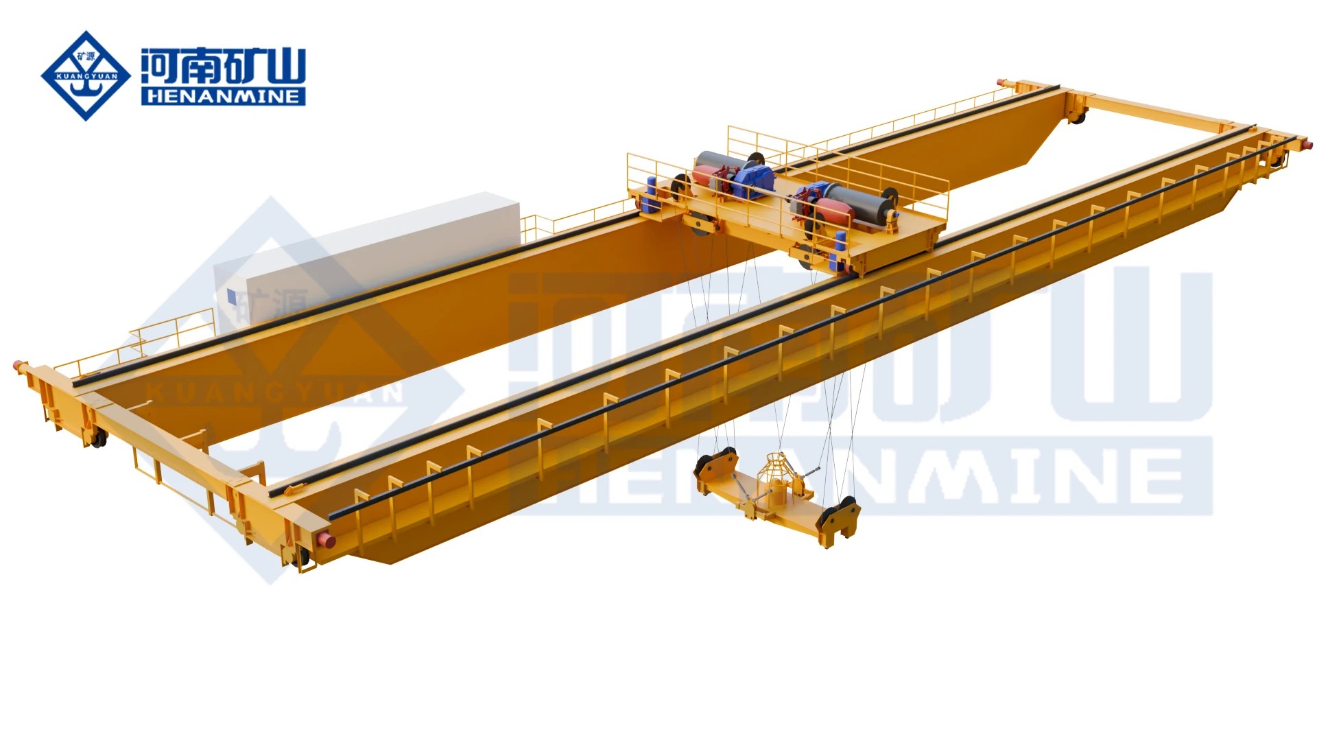
Double Trolley Overhead Crane (QE)

Two hook trolleys provide separate lifting points for long components or independent tasks. Confirm each trolley rating and the permitted combined lifting operation.

Capacity5+5 / 10+10 / 16+16 t
Span10.5–31.5 m in 3 m steps
Working classA5 or A6
All specifications
Model QE
Rated capacity 5+5 / 10+10 / 16+16 t
Span 10.5–31.5 m in 3 m steps
Lifting height 16 m for the listed configurations
Working duty A5 or A6
Hoisting speed A5, 5+5 / 10+10 / 16+16 t: 11.3 / 8.5 / 7.9 m/min
Trolley / bridge travel A5 trolley, same order: 37.2 / 43.8 / 44.6 m/min
Lifting arrangement Two winch trolleys with separate hooks
Control Independent or coordinated lifting; cabin, pendant or radio
Power supply 380 V / 50 Hz, three-phase; destination supply by specification
Operating environment Long-load handling in workshops or outdoor storage
A6 hoisting speed 5+5 / 10+10 / 16+16 t: 15.6 / 13.2 / 10.7 m/min
Bridge speed examples 5+5 t A5 at 10.5 m: 90.7 m/min; 16+16 t A5 at 10.5 m: 87.6 m/min
KSQE new-design double-trolley hook crane, manufacturer view 1
KSQE

Modular Double Trolley Overhead Crane (KSQE)

A modular double-trolley bridge for separate lifts or a coordinated two-point handling sequence. Define the load distribution and required hook spacing before selecting the arrangement.

CapacityEach trolley rated for its maximum reaction; combined lifting rating specified separately
SpanCustom rail-centre span to the production bay
Working classSelected from load spectrum, lifts per hour and operating shifts
All specifications
Model KSQE
Rated capacity Each trolley rated for its maximum reaction; combined lifting rating specified separately
Span Custom rail-centre span to the production bay
Lifting height Custom hook travel from pickup to placement level
Working duty Selected from load spectrum, lifts per hour and operating shifts
Hoisting speed Configured for independent and coordinated lifting
Trolley / bridge travel Coordinated trolley and bridge travel to the load-handling sequence
Lifting arrangement Two hooks; Two trolleys on common track
Control Independent/tandem control with feedback and operating interlocks
Power supply Three-phase supply matched to destination voltage and frequency
Operating environment Industrial service package matched to site conditions
Trolley arrangement Two winch trolleys on a compact modular double-girder bridge
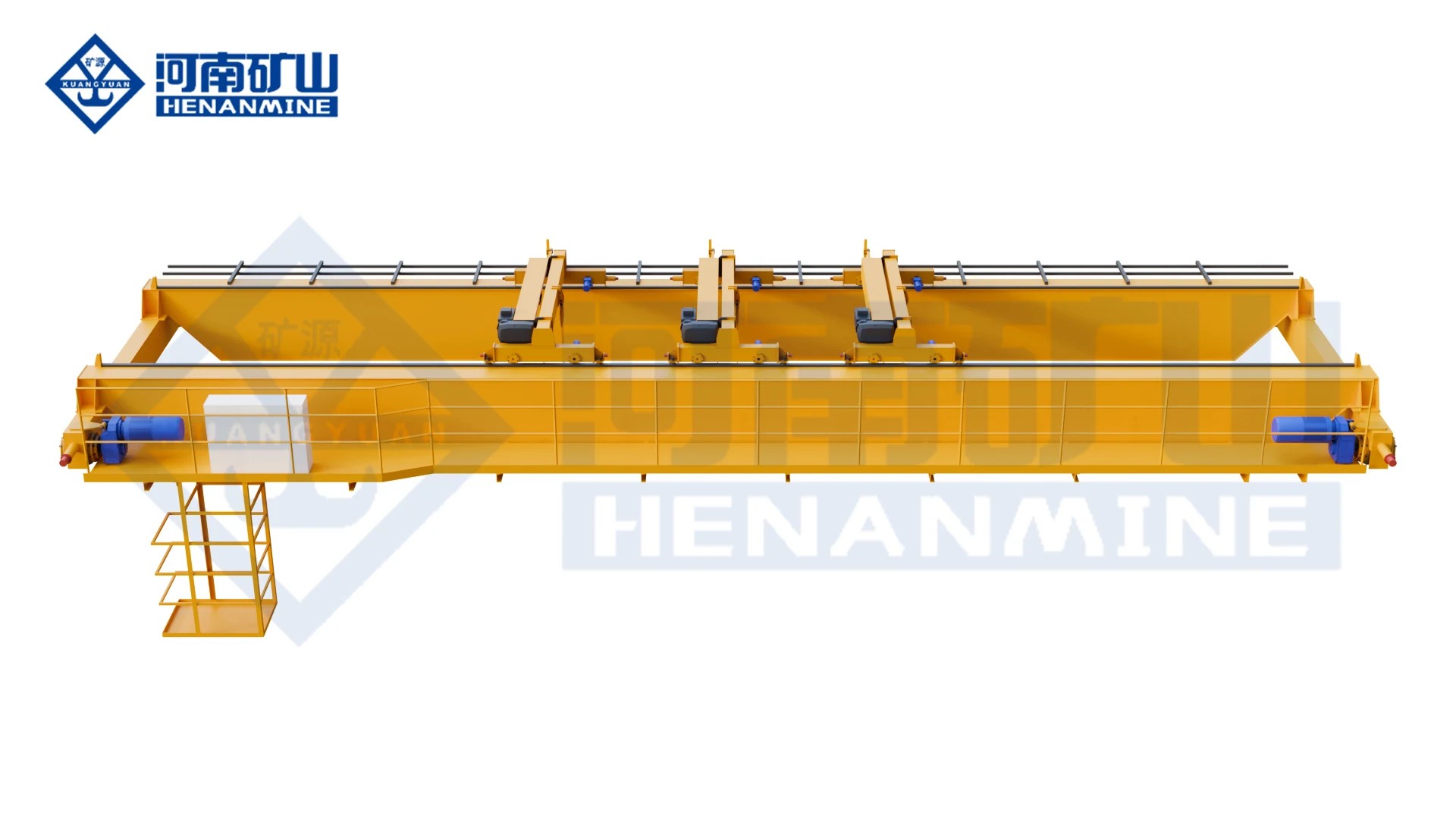
QES three-trolley hook crane, manufacturer view 1
QES

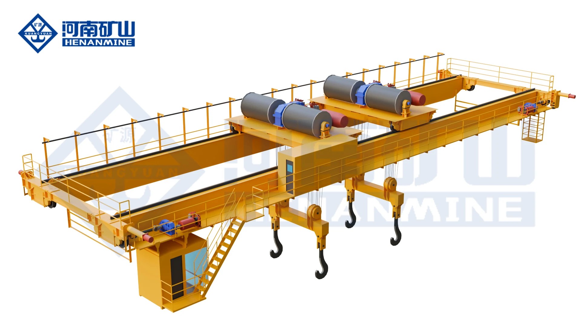
Three Trolley Overhead Crane for Paper Mills (QES)

Three hook trolleys support paper-machine rolls, large components and maintenance work. The offer defines individual trolley use and the approved paired lifting cases.

CapacityThree individual trolley ratings and approved combined-load cases
SpanCustom rail-centre span to the production bay
Working classSelected from load spectrum, lifts per hour and operating shifts
All specifications
Model QES
Rated capacity Three individual trolley ratings and approved combined-load cases
Span Custom rail-centre span to the production bay
Lifting height Custom hook travel from pickup to placement level
Working duty Selected from load spectrum, lifts per hour and operating shifts
Hoisting speed Selected for roll, shaft and machine handling
Trolley / bridge travel Speeds matched to single- and paired-trolley operations
Lifting arrangement Hooks; Three trolleys
Control PLC sequence control; paper-machine DCS interface available
Power supply Three-phase supply matched to destination voltage and frequency
Operating environment Industrial service package matched to site conditions
Trolley arrangement Three hook trolleys; independent or approved paired operation

Electric-hoist bridges

Choose a packaged electric hoist on a double-girder bridge, with one, two or three trolleys to suit the lifting points and available headroom.

LH electric-hoist double-girder crane, manufacturer view 1
LH

Electric Hoist Double Girder Overhead Crane (LH)

Lift routine workshop and warehouse components with an LH electric-hoist double-girder crane configured for the required capacity, hook height and duty.

Capacity3 / 5 / 10 / 16 / 20 t
Span10.5–31.5 m in 3 m steps for the listed configurations
Working classA3–A4 for the listed configurations
All specifications
Model LH
Rated capacity 3 / 5 / 10 / 16 / 20 t
Span options 10.5 / 13.5 / 16.5 / 19.5 / 22.5 / 25.5 / 28.5 / 31.5 m
Lifting height 3 t: 6 / 9 / 12 m; 5 t: 6 / 9 / 12 / 18 m; 10–20 t: 9 / 12 m
Crane duty A3–A4
Hoisting speed 3 / 5 t: 8 or 8/0.8; 10 t: 7 or 7/0.7; 16 t: 3.5 or 3.5/0.35; 20 t: 6 or 6/0.6 m/min
Trolley travel speed 20 m/min
Bridge travel speed 3–16 t: 20 or 30 m/min; listed 20 t configuration: 20 m/min
Hoist package 3–16 t: CD1 / MD1; 20 t: HC / HM
Trolley arrangement One seated electric-hoist trolley
Control Pendant; radio control by order
Standard power supply 380 V / 50 Hz / three-phase; destination supply by order
Working environment General indoor production, storage, assembly and maintenance
Custom configurations Capacity, span, hook travel and control package to project requirements
KSSL new-design electric-hoist double-girder crane, manufacturer view 1
KSSL

European Type Double Girder Hoist Crane (KSSL)

A compact electric-hoist bridge with dual-speed lifting and variable-frequency travel. Match the hoist capacity, useful hook height and positioning needs to the workshop.

CapacityCustom rating for the complete suspended load
SpanCustom rail-centre span to the production bay
Working classSelected from load spectrum, lifts per hour and operating shifts
All specifications
Model KSSL
Rated capacity options 5–80 t in the standard A5 configuration range
Span options 7.5–31.5 m
Lifting height options 3–20 m
Crane duty A5 for the standard configuration range
Hoisting speed Normal and positioning speeds matched to the selected hoist capacity
Trolley travel Variable-frequency drive
Bridge travel Variable-frequency drive
Hoist layout Compact C-shaped electric wire-rope hoist with large-diameter rope drum
Trolley quantity One
Control options Pendant / radio / cabin according to the selected package
Standard power supply 380 V / 50 Hz / three-phase; destination supply by order
Monitoring option Remote equipment monitoring and maintenance diagnostics
Custom configurations Capacity, dimensions, hoist, controls and service conditions reviewed for the project
LHE double-trolley electric-hoist crane, manufacturer view 1
LHE

Double Trolley Electric Hoist Overhead Crane (LHE)

Two electric-hoist trolleys handle separate loads or support a long component at two points. Individual ratings and combined operation follow the actual load distribution.

CapacityTwo separate trolley ratings, matched to the actual load distribution
SpanCustom rail-centre span to the production bay
Working classSelected from load spectrum, lifts per hour and operating shifts
All specifications
Model LHE
Bridge arrangement Double girder overhead bridge
Trolley quantity 2
Lifting mechanism Two compact steel wire-rope electric hoists
Rated capacity Individual trolley ratings and combined bridge rating selected from the load cases
Span Matched to the runway rail-centre distance
Lifting height Matched to pickup and placement levels
Hook spacing Minimum and maximum spacing matched to component lifting points
Crane duty Selected from load spectrum, lifts per hour and operating shifts
Hoisting speed Matched to each hoist capacity and positioning requirement
Trolley & bridge travel Soft-start or VFD drives
Operating modes Independent or coordinated two-trolley operation
Coordinated controls Encoder and inverter control package selected for the paired lift
Lifting attachment Hooks or specified lifting attachment
Power supply Three-phase voltage and frequency matched to the destination supply
Working environment General industrial production, assembly and maintenance
LHEA low-headroom double-trolley electric-hoist crane, manufacturer view 1
LHEA

Low Headroom Double Trolley Hoist Crane (LHEA)

A low-headroom bridge with two seated electric-hoist trolleys. Compare the usable hook height, lifting-point spacing and individual or combined ratings for the component.

CapacityCustom individual-trolley and combined-load ratings
SpanCustom rail-centre span to the production bay
Working classSelected from load spectrum, lifts per hour and operating shifts
All specifications
Model LHEA
Bridge arrangement Lightweight double girder overhead bridge
Trolley quantity 2
Lifting mechanism Two seated electric hoists mounted on trolley frames
Rated capacity Individual trolley ratings and combined bridge load selected for the component
Span Matched to runway rail-centre distance
Lifting height Matched to pickup and highest placement levels
Hook spacing Selected minimum and maximum spacing within the trolley travel range
Headroom arrangement Low-headroom seated-hoist layout
Crane duty Selected from load spectrum and operating cycle
Hoisting & travel speeds Matched to the ordered hoist capacities and handling cycle
Control Independent or paired operating functions as specified
Lifting attachment Hooks or project-specific attachment
Wheels & drives Forged-wheel and travel-drive package confirmed in the technical offer
Crane weight & wheel reactions Configuration values provided with the crane drawing
Power supply Voltage and frequency matched to the destination supply
KSSLE double-girder overhead crane with two compact electric-hoist trolleys and two hooks
KSSLE

Double Trolley Electric Hoist Overhead Crane (KSSLE)

Two compact electric-hoist trolleys provide separate lifting positions or a coordinated two-point lift. Specify the working envelope and approved combined load.

CapacityCustom per-trolley and combined lifting ratings
SpanCustom rail-centre span to the production bay
Working classSelected from load spectrum, lifts per hour and operating shifts
All specifications
Model KSSLE
Bridge arrangement Double girder overhead bridge
Trolley quantity 2 on a common trolley track
Lifting mechanism Two compact new-type electric wire-rope hoists
Rated capacity Individual trolley ratings and combined load selected for the lifting cases
Span Matched to runway rail-centre distance
Lifting height Matched to pickup and placement levels
Hook spacing Minimum and maximum working spacing selected for the component
Crane duty Matched to load spectrum, handling frequency and operating shifts
Hoisting Dual-speed lifting; speed pair selected for each hoist
Trolley & bridge travel Variable-frequency drives
Operating modes Independent or coordinated handling; balanced turning when specified
Hoist layout Compact C-shaped arrangement with large-diameter rope drums
Operator control Control station and operating functions matched to the application
Monitoring option Remote condition monitoring and maintenance functions
Power supply Three-phase voltage and frequency matched to the destination supply
KSSLS bridge crane showing three hoist units and three suspended hooks
KSSLS

Three Trolley Electric Hoist Overhead Crane (KSSLS)

Three electric-hoist trolleys serve paper-machine components and maintenance positions. Select their individual capacities and the permitted handling sequence together.

CapacityThree individual hoist ratings and permitted combined lifting cases
SpanCustom rail-centre span to the production bay
Working classSelected from load spectrum, lifts per hour and operating shifts
All specifications
Model KSSLS
Bridge arrangement Double girder overhead bridge
Trolley quantity 3
Lifting mechanism Three compact new-type electric-hoist trolleys
Rated capacity Three individual hoist ratings and specified combined-load cases
Span Matched to runway rail-centre distance
Lifting height Matched to component pickup and landing levels
Trolley spacing Working separation and approach limits selected for the machine layout
Crane duty Selected from the component load spectrum and operating frequency
Hoisting Dual-speed normal and positioning lifting
Trolley & bridge travel Variable-frequency drives
Operating combinations Individual and project-defined coordinated modes
Hoist layout Compact C-shaped arrangement with large-diameter rope drums
Primary use Paper-industry large-workpiece handling and equipment maintenance
Monitoring option Remote equipment monitoring and maintenance functions
Power supply Three-phase voltage and frequency matched to the destination supply

Steel & magnetic handling

Match the crane, carrier beam and lifting attachment to plates, bars, sections, ingots or other compatible ferromagnetic stock.

QC overhead crane showing the lifting magnet, winch trolley and service platform
QC

Electromagnetic Overhead Crane (QC)

Lift compatible ferromagnetic stock with a hook-suspended electromagnet; include magnet tare, material form and any auxiliary-hook duty.

Capacity5 / 10 / 16 t magnet; 16/3.2 / 20/5 / 32/5 t main/auxiliary
Span10.5–31.5 m in 3 m steps
Working classA6 for the listed configurations
All specifications
Model QC
Magnetic lifting selections 5 / 10 / 16 t; capacity includes the lifting magnet
Main-magnet / auxiliary-hook selections 16/3.2 / 20/5 / 32/5 t
Span 10.5–31.5 m in 3 m steps
Working duty A6 for the listed configurations
Magnet-only lifting height 5 / 10 / 16 t: 16 m
Main / auxiliary lifting height 16/3.2 and 32/5 t: 16/18 m; 20/5 t: 12/14 m
Magnet-only hoisting speed 5 / 10 / 16 t: 15.6 / 13 / 13 m/min
Main / auxiliary hoisting speed 16/3.2 t: 13/14.6; 20/5 t: 12.6/15.5; 32/5 t: 9.5/15.5 m/min
Trolley travel Magnet-only 5 / 10 / 16 t: 39.5 / 43.8 / 44.5 m/min
Lifting arrangement Hook-suspended electromagnet; auxiliary hook on selected versions
Hook swivel with magnet Locked against rotation for the listed hook-suspended arrangement
Power supply 380 V / 50 Hz, three-phase; destination supply and magnet circuit specified with the order
Magnet holding on power loss Backup holding duration, alarms and acceptance test selected for the actual magnet and load
Material temperature Magnet and cable package selected for the stated pickup temperature
Capacity definition Complete suspended load includes magnet and lifting equipment; steel payload must also meet magnet capacity
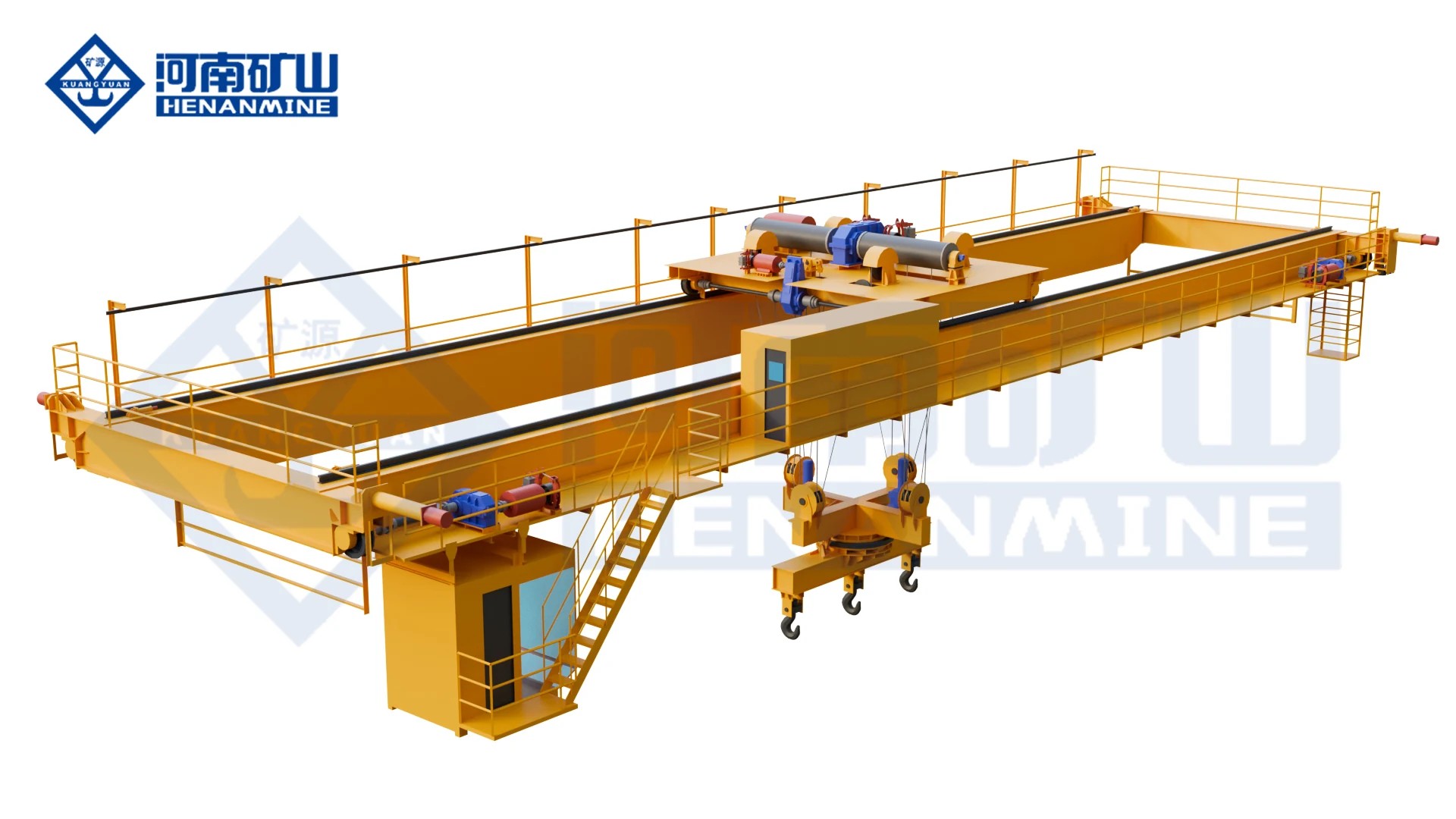
QL double-girder bridge with two hoisting units and two suspended hooks
QL

Electromagnetic Carrier Beam Overhead Crane (QL)

Handle long steel plate, ingots or sections with an electromagnetic carrier beam matched to the complete steel load.

Capacity10+10 / 12.5+12.5 / 13.5+13.5 t listed selections
Span28.5 / 28.5 / 31.5 m, in the same capacity order
Working classA6 / A7 / A7, in the same capacity order
All specifications
Model QL
Lifting arrangement Electromagnetic carrier beam; beam orientation and rotation selected with the order
Listed rotating capacity selections 10+10 / 12.5+12.5 / 13.5+13.5 t
Listed rotating spans 28.5 / 28.5 / 31.5 m, in the same capacity order
Listed rotating lifting heights 16 / 10 / 13 m, in the same capacity order
Listed rotating working duty A6 / A7 / A7, in the same capacity order
Listed rotating hoisting speed 11.4 m/min
Listed trolley / bridge travel 38 / 88 m/min
Listed rotation range / speed ±180° / 0.8 r/min for the rotating configuration
Magnet holding on power loss 15–30 minute battery-holding package; selected duration and test load in the order
Power supply Listed rotating configurations: 380 V / 50 Hz, three-phase; magnet circuit specified separately
Capacity definition Listed rotating capacity includes carrier beam and dedicated lifting attachments; net steel payload stated separately
Operating environment Listed rotating configurations: indoor; outdoor, dust and temperature package by specification
Magnet pattern Beam length, magnet quantity and spacing matched to steel dimensions and pickup conditions
Power calculation Crane drive power and dedicated attachment power identified separately
YC upper-rotating magnetic-beam overhead crane with trolley turntable and two magnets
YC

Upper Rotating Magnetic Beam Overhead Crane (YC)

Turn a magnetic beam and compatible steel load with an upper-rotating trolley after checking the rotation envelope and pickup positions.

Capacity5+5–25+25 t family; configured to beam and steel load
Span10.5–31.5 m family
Working classA6–A7 family
All specifications
Model YC
Lifting arrangement Upper trolley rotates on a circular track above the lower trolley
Listed lifting selections 5+5 / 10+10 / 16+16 / 25+25 t; includes carrier beam and dedicated attachments
Listed span selections 25 / 28.5 / 33 / 34 m, paired to capacity and duty in the configuration table
Listed lifting heights 10 / 12 / 16 m, paired to the selected configuration
Listed working duty A6 / A7 according to configuration
Listed hoisting speeds 12.4 / 12.6 / 14.8 / 16 / 15.4 m/min by configuration
Listed trolley travel 39–48 m/min by configuration
Listed bridge travel 85.2–107 m/min by configuration
Listed beam rotation speed 1.36–1.85 r/min by configuration
Rotation range Up to 360° upper-trolley rotation; ordered range matched to the material route
Magnet holding on power loss 15–30 minute battery-holding package; duration and test conditions specified with the order
Control PLC/HMI; variable-frequency motion and anti-sway functions selected for the handling task
Listed configuration supply 380 V / 50 Hz, three-phase; destination electrical package can be specified
Operating environment Listed numeric combinations: indoor; outdoor, temperature and dust package specified separately
Power calculation Crane drive power and magnet/attachment power identified separately
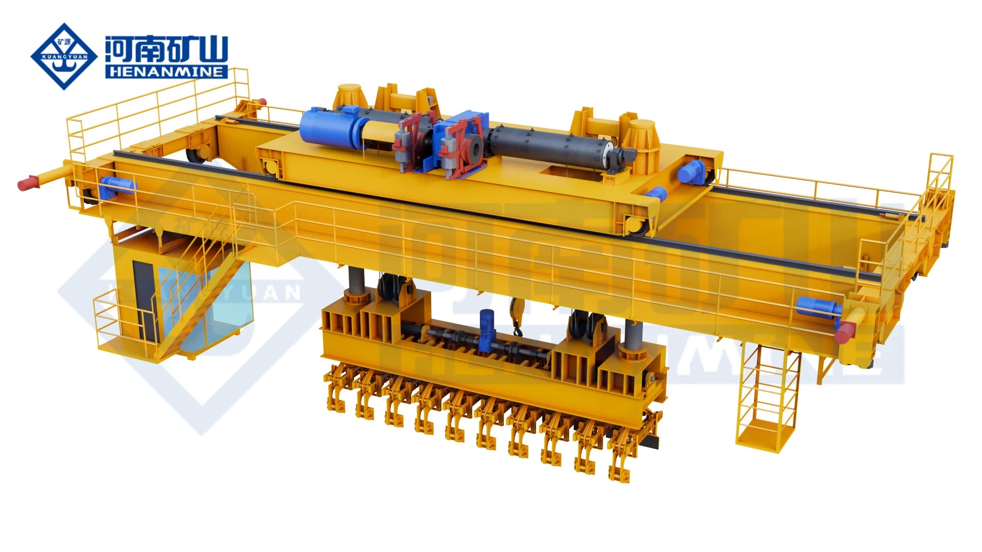
QLC double-girder overhead crane with a lower rotating magnetic carrier beam
QLC

Lower Rotating Magnetic Beam Overhead Crane (QLC)

Position compatible steel products with a lower-rotating magnetic beam sized for stock dimensions, attachment weight and working clearances.

CapacityCustom rating including magnetic beam and steel payload
SpanCustom rail-centre span to the production bay
Working classSelected from load spectrum, lifts per hour and operating shifts
All specifications
Model QLC
Crane capacity Selected for steel plus rotating beam, magnets and other suspended equipment
Net steel payload Stated separately with the selected magnet and complete attachment weight
Span / runway length Matched to the working bay and material-transfer route
Lifting height Matched to pickup, stack and landing levels with the selected attachment
Working duty Selected for load spectrum, lifts per hour and rotation frequency
Hoisting / travel speed Matched to the load, production cycle and positioning requirement
Lifting arrangement Lower rotating electromagnetic carrier beam
Magnet layout Beam length, magnet quantity and spacing matched to product size and magnetic pickup
Rotation range Selected for pickup and landing orientation
Rotation control Photoelectric angle sensing with rotation-limit braking
Mechanical anti-sway Bidirectional V-rope arrangement
Electrical anti-sway Selected motion-control package; acceptance performance defined for the operating conditions
Magnet holding on power loss 15–30 minute battery-holding package; required duration and test load in the order
Material temperature Magnet, cable and protection package matched to actual pickup temperature
Power supply Three-phase site supply and dedicated magnet power equipment selected with the package
QJ double-girder overhead crane with lower rotating carrier beam and lifting hooks
QJ

Lower Rotating Carrier Beam Overhead Crane (QJ)

Turn steel products with a lower-rotating carrier beam matched to the attachment, turning envelope and complete suspended load.

CapacityCustom rating for steel, carrier beam and attachment
SpanCustom rail-centre span to the production bay
Working classSelected from load spectrum, lifts per hour and operating shifts
All specifications
Model QJ
Lifting arrangement Lower rotating carrier beam with electromagnets or mechanical clamps
Crane capacity Selected for product plus carrier beam, attachment and other suspended equipment
Product payload Stated for the selected attachment and complete load case
Span / runway length Matched to the working bay and material route
Lifting height Matched to pickup and landing levels with the selected attachment depth
Working duty Selected for load spectrum, shifts, lifts per hour and rotation frequency
Hoisting / trolley / bridge speeds Selected for the load, transfer distance and positioning task
Rotation range Matched to required horizontal orientation change
Rotation control Photoelectric angle sensing with configured rotation-limit stopping
Mechanical anti-sway Bidirectional V-rope arrangement
Electrical anti-sway Selected motion-control package; acceptance performance agreed for operating conditions
Operator controls PLC/HMI and master-controller arrangement selected for the job
Attachment conditions Magnet contact and material range, or clamp grip range and permissible contact
Material temperature Attachment, cables and protection selected for the actual pickup temperature
Power supply Three-phase supply and attachment services matched to the destination site
Power-loss response Defined for the selected magnetic or mechanical gripping system

Grab & multi-purpose cranes

Compare four-rope grab handling with separate hook, magnet and multipurpose modes. Useful payload depends on the attachment tare as well as the crane rating.

QZ double-girder grab overhead crane with winch trolley and four-rope clamshell grab
QZ

Double Girder Grab Overhead Crane (QZ)

Move bulk material through repeated grab pickup, travel and discharge cycles with a four-rope QZ crane.

Capacity5 / 10 / 16 / 20 t; rated load includes grab self-weight
Span5/10 t: 10.5–31.5 m; 16/20 t: 16.5–31.5 m
Working classA6 for the listed configurations
All specifications
Model QZ
Rated suspended load 5 / 10 / 16 / 20 t, including grab self-weight
Span 5 / 10 t: 10.5–31.5 m; 16 / 20 t: 16.5–31.5 m, in 3 m steps
Maximum lifting height 5 / 10 / 16 / 20 t: 20 / 18 / 22 / 26 m
Crane duty A6 for the listed standard selections
Hoisting speed 5 / 10 / 16 / 20 t: 40.1 / 40.7 / 41.8 / 48.6 m/min
Trolley travel speed 5 / 10 / 16 / 20 t: 44.6 / 45.6 / 43.2 / 43.2 m/min
Bridge travel example 5 t, 10.5 m span: 93.7 m/min; other spans use their matched drive configuration
Lifting arrangement Four-rope grab with separate holding and closing winches
Grab volume ranges 5 t: 0.75–2.5; 10 t: 1.5–5; 16 t: 2.5–8; 20 t: 3–10 m³
Grab opening direction Parallel or perpendicular to the main girders, as selected
Control options Cabin / pendant / radio / remote; automated package by specification
Automation options Positioning, anti-sway and specified production or storage-system interfaces
Standard power supply 380 V / 50 Hz / three-phase; destination supply by order
Material selection Bulk density, lump size, moisture, fill behaviour, temperature and abrasiveness
Supply scope Crane, matched grab, controls and agreed material-handling functions
QP double-girder overhead crane showing separate grab and magnet lifting positions
QP

Grab and Magnet Double Girder Overhead Crane (QP)

Separate grab and magnet lifting mechanisms share one trolley for bulk solids and ferrous material. Rate each operating mode with its own attachment and payload.

CapacityGrab/magnet modes: 5/5 / 10/10 / 16/16 t
Span5/5 t: 10.5–31.5 m; 10/10 t: 13.5–31.5 m; 16/16 t: 19.5–31.5 m
Working classA6 for the listed configurations
All specifications
Model QP
Mode ratings 5/5 / 10/10 / 16/16 t for grab / magnet modes
Crane duty A6 for the listed standard selections
Trolley arrangement One trolley with separate grab and magnet lifting mechanisms
Span options 5/5 t: 10.5–31.5 m; 10/10 t: 13.5–31.5 m; 16/16 t: 19.5–31.5 m, in 3 m steps
Grab maximum lifting height 5/5 / 10/10 / 16/16 t: 20 / 18 / 22 m
Magnet maximum lifting height 5/5 / 10/10 / 16/16 t: 16 / 22 / 22 m
Grab hoisting speed 5/5 / 10/10 / 16/16 t: 40.1 / 40 / 41.8 m/min
Magnet hoisting speed 5/5 / 10/10 / 16/16 t: 15.6 / 10.4 / 13 m/min
Trolley travel speed 5/5 / 10/10 / 16/16 t: 44.6 / 45.6 / 43.2 m/min
Bridge travel Matched to capacity and span; 5/5 t at 10.5 m: 93.7 m/min
Grab lifting arrangement Separate holding and closing winches for a four-rope grab
Magnet lifting arrangement Auxiliary lifting mechanism; hook-suspended electromagnetic plate
5/5 t magnet example MW1-6: 4,540 kg nominal pickup + 460 kg magnet tare; 776 mm diameter
Operator controls Cabin or radio; selected PLC/HMI and mode-control functions
Standard power supply 380 V / 50 Hz / three-phase; destination and magnet supplies by order
QEN double-girder overhead crane with hook and grab lifting positions
QEN

Grab and Hook Double Girder Overhead Crane (QEN)

One bridge combines grab and hook functions for bulk solids and conventional loads. Define both handling cycles, attachment weights and separate mode ratings.

CapacitySeparate hook- and grab-mode ratings including attachment tare
SpanCustom rail-centre span to the production bay
Working classSelected from load spectrum, lifts per hour and operating shifts
All specifications
Model QEN
Bridge arrangement Double girder overhead bridge
Handling devices Hook and project-selected grab arrangement
Hook-mode rating Selected for workpiece plus rigging and attachment
Grab-mode rating Selected for grab tare plus maximum material payload
Span Matched to runway rail-centre distance
Lifting height Matched to pickup, discharge and equipment-placement levels
Crane duty Selected from both hook and bulk-handling cycles
Hoisting speed Selected for the approved hook and grab operating cases
Trolley & bridge motion Variable-frequency control package
Grab selection Volume, tare, shell and fill behaviour matched to material density
Grab power & control Power and control package matched to the selected grab; hydraulic drive where specified
Lifting & attachment layout Hook/grab positions and mechanisms defined in the offer; detachable hydraulic-grab configuration available
Wear parts Replaceable grab pins and teeth; selected spares package
Operator controls Selected operating station and hook/grab mode functions
Power supply Three-phase voltage and frequency matched to the destination supply
QS double-girder bridge and hook arrangement
QS

Hook, Grab and Magnet Overhead Crane (QS)

Switch between hook, grab and electromagnet duties with separate ratings and a defined sequence for each material stream.

CapacitySeparate hook, grab and magnet ratings including attachment tare
SpanCustom rail-centre span to the production bay
Working classSelected from load spectrum, lifts per hour and operating shifts
All specifications
Model QS
Crane type Double-girder bridge with exchangeable hook, grab and electromagnetic lifting modes
Hook rating Selected for the load plus rigging and any below-hook lifting equipment
Grab-mode loading Grab self-weight plus maximum carried material
Magnet-mode loading Magnet and suspension weight plus usable steel payload under specified pickup conditions
Span Rail-centre distance selected for the required bay
Lifting height Selected for pickup, discharge and the depth of each attachment
Working duty Selected from the combined hook, grab and magnet operating schedule
Hoisting / travel speeds Selected for the three operating cycles and required positioning
Electrical attachment connectors Heavy-duty plugs with IP55 enclosure protection
Control platform PLC module and HMI with master-controller operation
Controller functions Defined operating positions, return-to-zero and locking
Power supply Destination three-phase supply; grab and magnet circuits specified with their attachments
Mode changeover Attachment connection and control selection defined in the supplied package
Magnet power-loss provision Holding duration, alarm response and acceptance test specified where required

Hazardous & insulated cranes

Choose the required protection for a classified area, clean production process or electrically connected load. These requirements describe different lifting packages.

LHB double-girder bridge with electric-hoist trolley
LHB

Explosion-Proof Electric Hoist Overhead Crane (LHB)

Lift intermittently in a classified area with protected hoist, drives, controls and documents matched to the site classification.

CapacityCustom load rating for the protected electric-hoist package
SpanCustom rail-centre span to the production bay
Working classSelected from load spectrum, lifts per hour and operating shifts
All specifications
Model LHB
Bridge / lifting platform Double-girder bridge with seated explosion-protected electric hoist on a trolley frame
Capacity selection envelope 1–10 t; other requirements reviewed with the lifting package
Span selection envelope 7.5–28.5 m; extended spans by project design
Lifting-height selection envelope 6–20 m
Working-duty selection envelope A3–A5; hoist and crane duties selected for the actual operating cycle
Hoisting-speed selection envelope 2–10 m/min; selected speed stated with capacity and hoist
Bridge travel selection envelope 15–30 m/min; operating speed selected with protected drives
Trolley travel Selected with the protected hoist-trolley arrangement
Headroom arrangement Low-headroom seated hoist; final hook positions on arrangement drawing
Explosion protection Gas or dust package matched to the approved area classification
Gas selection data Hazardous medium, zone/group, temperature class and ambient conditions
Dust selection data Dust type/group, area classification and permitted surface temperature
Controls Protected pendant or radio configuration selected for the area
Power supply 380 V / 50 Hz reference; destination voltage and frequency configured with the order
Runway loading Crane mass and wheel reactions supplied for the selected span and load
QB double-girder bridge and hook configuration
QB

Explosion-Proof Double Girder Overhead Crane (QB)

A protected winch-trolley crane with single-hook or main/auxiliary-hook selections. Compare the listed capacities, duty and speeds with the required hazardous-area package.

Capacity5 / 10 / 16/3.2 / 20/5 / 32/5 / 50/10 t
Span10.5–31.5 m in 3 m steps
Working classA3–A4 for the listed configurations
All specifications
Model QB
Single-hook ratings 5 / 10 t
Main / auxiliary-hook ratings 16/3.2 / 20/5 / 32/5 / 50/10 t
Span selections 10.5 / 13.5 / 16.5 / 19.5 / 22.5 / 25.5 / 28.5 / 31.5 m
Listed working duty A3–A4
5 / 10 t lifting height 16 m; no auxiliary hook
16/3.2 and 32/5 t main / auxiliary lift 16/18 m
20/5 and 50/10 t main / auxiliary lift 12/14 m
Hoisting speeds 5 t: 3.7; 10 t: 3.3; main/auxiliary selections shown in the configuration table, m/min
Trolley travel 5 / 10 / 16/3.2 / 20/5 / 32/5 / 50/10 t: 9.3 / 10.3 / 10.3 / 10.3 / 9.8 / 8.9 m/min
Bridge travel 12–12.6 m/min for listed conventional selections, dependent on rating and span
Gas protection selections IIB T4 or IIC T4 configuration; exact equipment marking and document scope confirmed with the order
Gas hazardous zones Zone 1 or 2 selection subject to the specified gas and equipment protection
Dust protection Separate dust classification, temperature limits and protected equipment package
Controls Protected ground control; cabin or selected VFD-control arrangement by specification
Reference power supply 380 V / 50 Hz, three-phase; destination supply selected with the electrical package
Rail recommendation 5/10 t: P43; 16/3.2 and 20/5 t: P43/QU70; 32/5 t: QU70; 50/10 t: QU80 or QU100
Runway design data Span-specific mass and maximum wheel pressure shown below; final reactions confirmed for the ordered crane
ZJJB bridge and enclosed lifting-trolley arrangement
ZJJB

Cleanroom Explosion-Proof Overhead Crane (ZJJB)

Combine cleanroom contamination controls with the explosion-protection package required by the approved process area.

CapacityCustom rating for the clean and explosion-protected lifting package
SpanCustom rail-centre span to the production bay
Working classSelected from load spectrum, lifts per hour and operating shifts
All specifications
Model ZJJB
Capacity selection envelope 1–32 t; custom load and attachment arrangement reviewed for the process
Reference span envelope 7.5–28.5 m; final rail-centre span selected for the room
Reference lifting-height envelope 6–20 m
Reference working-duty envelope A3–A5; duty and mechanism selection matched to the operating cycle
Hoisting / travel speeds VFD-controlled motion; selected speeds and positioning requirements stated with the load and process
Cleanliness requirement Room/process class and particle limits specified for the installation and acceptance conditions
Explosion protection Gas or dust configuration matched to the approved area specification
Mechanical measures Anti-static treatment and spark-suppression measures for the relevant components
Surface coating High-pressure anti-static coating; surface finish selected for cleaning and process exposure
Sealed areas Crane body, drive areas and connection gaps configured to reduce dust accumulation
Wear-debris measures Selected corrosion-resistant materials with collection devices in relevant wear areas
Stainless components Passivated stainless hook, wheel or relevant contact-component configuration as specified
Lubricants and cleaning Selected for process restrictions, seal compatibility and maintenance procedure
Controls Protected operator/control equipment selected for the area and process
Power supply 380 V / 50 Hz reference; destination supply and protected electrical package specified with the order
QBE bridge with two open winch trolleys
QBE

Double Trolley Explosion-Proof Overhead Crane (QBE)

Two protected trolleys serve separate tasks or an engineered tandem lift in a classified bay. Define the per-trolley ratings, shared load and permitted combined operation.

CapacityTwo individual trolley ratings plus approved tandem capacity
SpanCustom rail-centre span to the production bay
Working classSelected from load spectrum, lifts per hour and operating shifts
All specifications
Model QBE
Lifting arrangement Two explosion-protected trolley lifting systems on one double-girder bridge
Example rated arrangement 20+20 t; each trolley has its own stated rating
Other trolley ratings Selected for the actual load distribution and working duty
Permitted tandem load Engineered for the stated trolley positions, load shares, rigging and control mode
Reference span envelope 10–35 m; final span selected for the production bay
Reference lifting-height envelope 6–30 m
Reference working-duty envelope A4–A6; crane and individual mechanism duties selected for the operating cycle
Independent operation Individual trolley use within its permitted load and operating conditions
Coordinated operation Selected tandem mode with agreed control behavior and operating limits
Coordination technology Encoder and inverter-based double-trolley control
Hoisting / trolley speeds Selected for the independent and coordinated modes; each specified with its load case
Trolley separation Minimum/maximum operating spacing agreed from load geometry and trolley envelopes
Operator controls Cabin, pendant, radio or PLC-linked arrangement selected for the area and process
Explosion protection Mechanical and electrical package matched to the approved gas or dust area specification
Power supply 380 V / 50 Hz reference; destination voltage and frequency specified with the protected equipment
Monitoring / interlocks Mode, motion and fault-response functions specified for the approved tandem lift
QY double-girder bridge and lifting trolley
QY

Insulated Overhead Crane (QY)

Lift in an electrolytic process with insulated interfaces and an A6 hook-crane package matched to the energized load path.

Capacity5 / 10 / 16/3.2 / 20/5 t
Span10.5–31.5 m in 3 m steps
Working classA6 for the listed configurations
All specifications
Model QY
Bridge arrangement Double girder, top-running overhead bridge
Standard rated loads 5 t; 10 t; 16/3.2 t; 20/5 t
Standard spans 10.5, 13.5, 16.5, 19.5, 22.5, 25.5, 28.5 and 31.5 m
Maximum lifting height 5 and 10 t: 16 m; 16/3.2 t: main 16 m / aux 18 m; 20/5 t: main 12 m / aux 14 m
Working class A6 for the listed configurations
Hoisting speeds 5 t: 15.6; 10 t: 10.4; 16/3.2 t: 10.7/14.6; 20/5 t: 9.8/15.5 m/min
Trolley speeds 5 t: 37.2; 10 t: 43.8; 16/3.2 and 20/5 t: 44.6 m/min
Bridge speeds 76–93.7 m/min; see the exact load/span row below
Electrical isolation Insulating pads, sleeves and plates at defined load-path interfaces
Insulation acceptance Test values, method and inspection points specified for the process
Motion-control options Speed control and positioning selected for the handling cycle
Environment Electrolytic/non-ferrous process service; heat and corrosion protection specified for exposure
Power supply Listed configurations: 380 V, 50 Hz, three-phase; destination alternatives by specification
Rail and wheel load Configuration-specific values shown below
Custom configuration Capacity, hook arrangement and motion package matched to the required process
QYE insulated double-trolley bridge arrangement
QYE

Double Trolley Insulated Overhead Crane (QYE)

Two insulated trolleys handle separate tasks or a specified two-point lift. Confirm individual reactions, hook spacing and the coordinated lifting sequence for the process.

CapacityTwo individual trolley ratings from actual lifting-point reactions
SpanCustom rail-centre span to the production bay
Working classSelected from load spectrum, lifts per hour and operating shifts
All specifications
Model QYE
Bridge arrangement Double girder overhead bridge
Trolley arrangement Two insulated lifting trolleys
Load ratings Individual lifting-point ratings plus maximum permitted combined bridge load
Span Selected for runway rail-centre distance
Lifting height Selected for pickup, transfer and placement levels
Working hook spacing Minimum and maximum separation defined in the arrangement drawing
Working duty Selected from load spectrum, operating frequency and shifts
Hoisting speed Selected for individual and coordinated lifting cases
Trolley and bridge travel Speed-control package selected for the handling cycle
Coordinated control Encoder feedback and inverter control
Electrical isolation Insulating pads, sleeves and plates at specified interfaces
Isolation acceptance Test performance and inspection points defined for both lifting paths
Operator control Operating station and trolley selection functions defined in the offer
Environment Thermal, dust and corrosion conditions specified for the installation
Power supply Three-phase voltage and frequency matched to the destination supply

Foundry & metallurgical cranes

Select the lifting arrangement for the actual ladle, slab, charging box or quenching process, including load temperature and the handling sequence.

LHY double-girder bridge with metallurgical electric hoist
LHY

Metallurgical Electric Hoist Overhead Crane (LHY)

Handle defined molten-metal loads with a metallurgical electric-hoist bridge and thermal and safety protection for the complete suspended load.

CapacityCustom rated load including ladle and lifting equipment
SpanCustom rail-centre span to the production bay
Working classSelected from load spectrum, lifts per hour and operating shifts
All specifications
Model LHY
Bridge arrangement Double girder electric-hoist overhead crane
Lifting mechanism Dedicated metallurgical electric hoist
Load-handling device Hook; ladle/attachment interface matched to the application
Rated capacity Selected from metal, ladle, fixture and other suspended loads
Span Matched to production-bay rail-centre distance
Lifting height Matched to ladle pickup, transfer and placement levels
Working duty Selected from load spectrum, lifts per hour and shifts
Hoisting speed Selected for metallurgical lifting and controlled placement
Trolley and bridge travel Selected for route length, cycle and positioning
Braking Double-brake hoist arrangement
Overload protection Metallurgical hoist protection package
Hoisting limits Dual limit protection
Wheels Forged wheels
Drive motors Special-purpose motors matched to the metallurgical configuration
Heat and dust protection Matched to ambient temperature, radiant heat and dust
Power supply Three-phase voltage and frequency matched to destination supply
Ladle tilting Separate handling device/control scope where required
YB slab-handling bridge with suspended mechanical tong
YB

Slab Handling Overhead Crane (YB)

Transfer and stack steel slabs with a gripping attachment matched to slab size, temperature, grip range and stack geometry.

CapacityCustom load rating for slab plus gripping attachment
SpanCustom rail-centre span to the production bay
Working classSelected from load spectrum, lifts per hour and operating shifts
All specifications
Model YB
Crane type Metallurgical overhead crane for slab handling
Product handled High-temperature or ambient-temperature steel slabs
Lifting attachment Slab clamp matched to product dimensions and gripping conditions
Rated capacity Selected from maximum slab load plus clamp and suspended equipment
Clamp opening Matched to minimum and maximum slab gripping dimensions
Gripping arrangement Matched to geometry, permitted contact surfaces and stack access
Span Matched to production-bay rail-centre distance
Lifting height Matched to pickup/discharge levels and maximum stack height
Working duty Selected from slab mass distribution, moves per hour and shifts
Hoisting speed Selected for pickup, transfer and controlled stacking
Trolley and bridge travel Selected for storage lanes, route length and production cycle
Operating control PLC module, HMI touch screen and WLK master controller
Master-controller functions Defined detents, zero-position return and locking
Thermal protection Heat protection for main girders, end beams and specified components
Wheels Forging and rolling composite manufacturing process
Slab temperature Specified separately from workshop ambient temperature
Power supply Three-phase voltage and frequency matched to destination supply
YH quenching-crane bridge and lifting trolley
YH

Quenching Overhead Crane (YH)

Move workpieces from furnace to quench bath within the heat-treatment sequence, with travel timing and vertical motion matched to the process.

CapacityCustom rating for workpiece, fixture and retained fluid loads
SpanCustom rail-centre span to the production bay
Working classSelected from load spectrum, lifts per hour and operating shifts
All specifications
Model YH
Crane type Metallurgical overhead crane for heat-treatment quenching
Handled load Hot workpiece plus fixture and suspended lifting equipment
Rated capacity Selected for complete suspended load and handling sequence
Span Matched to production-bay rail-centre distance
Vertical travel Matched to furnace pickup, bath level and full immersion/withdrawal
Transfer interval Maximum furnace-to-immersion time specified by the process
Hoisting/lowering speed Fast motion package matched to approach, immersion and withdrawal
Trolley and bridge speed Selected from transfer distance and complete cycle time
Working duty Selected from batch weight, cycles per hour and shifts
Braking Double-brake arrangement
Emergency power Included; power-loss response specified for the process
Thermal protection Heat protection for main girders, end beams and specified equipment
Control Operator control with optional programmed automatic sequence
Automation options Automatic positioning, handling and rapid lift/lower sequence
Bath/fixture interface Matched to bath opening, depth and workpiece orientation
Quench medium Specified for splash, vapour, corrosion and any hazardous-area requirements
Power supply Three-phase voltage and frequency matched to destination supply
YX charging-box bridge with two lifting trolleys
YX

Charging Box Overhead Crane (YX)

Lift, transfer and tip furnace material boxes with the trolley arrangement, attachment and tipping sequence matched to the charging cycle.

CapacityCustom rating for fully charged box and lifting device
SpanCustom rail-centre span to the production bay
Working classA6–A7 family
All specifications
Model YX charging box overhead crane
Reference lifting capacity 5–50 t; ordered rating includes box, contents and suspended attachments
Reference rail-centre span 7.5–35 m; custom arrangement available
Reference lifting height 6–20 m; selected for pickup and discharge levels
Working class A6–A7, selected for the operating cycle
Operating functions Box pickup, transfer and specified tipping / discharge
Trolley arrangement Selected for the box; coordinated two-trolley configuration available
Motion speeds Selected lifting, trolley and bridge speeds stated in the offer
Weighing Electronic lifted-weight display and weight records; accuracy specified per order
Control system PLC, HMI and master controller; ordered operating station
Motor insulation Class H thermal insulation
Thermal protection Heat-resistant materials / insulating covers matched to exposure
Reference power supply 380 V / 50 Hz; destination voltage and frequency specified in the offer
Box attachment Matched to pickup points, centre of gravity and tipping geometry
Minimum order 1 complete crane or a project batch
YZ casting-crane bridge and main and auxiliary hoisting arrangement
YZ

Double Girder Ladle Casting Crane (YZ)

Transfer and pour molten metal with a heavy ladle-handling bridge and main/auxiliary lifting equipment selected for the complete task.

Capacity100/32 / 125/32 / 140/40 / 160/50 / 200/50 t listed selections
Span19 / 22 / 25 m according to selected capacity
Working classA7
All specifications
Model YZ double girder casting overhead crane
Reference main / auxiliary ratings 100/32, 125/32, 140/40, 160/50 and 200/50 t; other project ratings can be specified
Reference rail-centre spans 19, 22 and 25 m; available combinations shown below
Reference main lifting heights 18–25 m, according to combination
Reference auxiliary lifting heights 20–27 m, according to combination
Working class A7 reference arrangement; duty matched to actual molten-metal cycle
Bridge / trolley form Double girder bridge with main and auxiliary lifting functions on the selected trolley arrangement
Main load-handling device Gantry-type ladle carrier matched to the ladle lifting interfaces
Auxiliary load-handling device Hook for the specified auxiliary or ladle-tipping duty
Hoist control Stator-voltage speed regulation in the reference package; selected speeds stated in the offer
Travel control Variable-frequency speed control; selected trolley and bridge speeds stated in the offer
Upper hoist protection Dual upper overtravel protection; final device arrangement specified in the safety schedule
Controls PLC / HMI and master controller with zero-position return and locking
Thermal protection Main/end-girder and selected component heat protection for the specified exposure
Reference maximum wheel load 404–665 kN; combination and wheel arrangement dependent
Reference crane runway rail QU120 for the listed combinations
Reference power supply 380 V / 50 Hz / 3-phase AC; destination supply defined in the offer
Minimum order 1 complete crane or a project batch
YZD metallurgical bridge with main and auxiliary lifting hooks
YZD

Metallurgical Hook Overhead Crane (YZD)

Handle molten-metal loads with a metallurgical hook crane matched to the ladle carrier, lifting route and process protection.

Capacity5 / 10 / 16/3.2 / 20/5 / 32/5 / 50/10 / 74/20 t
Span5–50 t: 10.5–31.5 m; 74/20 t: 13.5–31.5 m
Working classA7 listed selections; A6–A8 engineered family
All specifications
Model YZD metallurgical hook overhead crane
Rated-load arrangements 5; 10; 16/3.2; 20/5; 32/5; 50/10; 74/20 t
Lifting mechanism Metallurgical winch trolley with forged hook; compatible ladle carrier
Rail-centre span 10.5–31.5 m for 5–50/10 t; 13.5–31.5 m for 74/20 t reference arrangements
Maximum main-hook lift 12, 16 or 22 m, according to rated arrangement
Maximum auxiliary-hook lift 14, 16, 18 or 24 m, where fitted; see combinations
Reference working class A7; other project-selected A6–A8 packages available
Reference main-hoist speeds 6.1–15.5 m/min; exact value depends on rated arrangement
Reference trolley speeds 33.8–44.6 m/min; see combinations
Reference bridge speeds 67.3–93.7 m/min; capacity and span dependent
Main thermal protection Heat-insulating layer beneath the main girders
Hoisting components Steel-core wire rope, forged hook and specified safety brake
Motor insulation Class H thermal insulation for the selected metallurgical motor package
Reference ambient temperature −10 to +60 °C for the listed A7 configuration basis; heat exposure specified separately
Reference humidity Relative humidity ≤50% at +40 °C for the listed configuration basis
Reference power supply 380 V / 50 Hz / 3-phase AC; destination supply matched in the offer
Crane rail P43, QU70, QU80 or QU100 by reference arrangement; see combinations
Minimum order 1 complete crane or a project batch

Underhung & transfer systems

Compare suspended bridges, multiple support tracks, rail-transfer interfaces and fixed-runway container handling around the building and working route.

LHDX double-girder crane with multiple suspension wheel sets
LHDX

Multi-Point Double Girder Underhung Crane (LHDX)

A wide double-girder hoist bridge carried by multiple suspended tracks. Define the support spacing, load distribution and usable hook coverage across the hall.

CapacityCustom rated load distributed across multiple suspension tracks
SpanCustom multi-track working width and support spacing
Working classSelected from load spectrum, lifts per hour and operating shifts
All specifications
Model LHDX
Crane arrangement Multi-point electric double-girder suspended bridge
Runway arrangement Multiple overhead suspended tracks
Lifting system Electric hoist selected for the handled load and operating cycle
Rated capacity Selected for the complete suspended load, hoist duty and bridge/support arrangement
Overall working width Selected from required hook coverage and the building support grid
Adjacent track spacing Specified separately for each support interval
Number of support tracks Selected from working width, crane loading and available support positions
Runway length Selected for the production and maintenance route
Usable lifting height Selected from pickup, transfer and placement levels
Working duty Selected from load spectrum, lifts per hour and operating shifts
Hoisting speed Selected with the electric hoist and positioning requirement
Trolley / bridge speeds Matched to travel distances and multi-support operating arrangement
Controls Operator station and travel coordination functions selected for the task
Suspension reactions Calculated for the final support layout and governing load positions
Modular changes Later working-zone or equipment changes reviewed against the existing crane and support layout
Power supply Destination three-phase voltage and frequency specified with the electrical package
KSX suspended transfer-crane bridges and electric-hoist arrangements
KSX

Double Girder Underhung Rail-Transfer Crane (KSX)

An underhung rail-transfer system connects handling sections so a hoist trolley can move between maintenance positions. Specify the transfer interfaces and individual bridge geometry.

CapacityCustom rated load for maintenance equipment and lifting gear
SpanCustom transfer-rail and bridge geometry
Working classSelected from load spectrum, lifts per hour and operating shifts
All specifications
Model KSX
Reference system rating 12.5 t for the linked handling arrangement
System composition Electric-hoist trolley, powered-travel suspended bridge, manual-travel suspended bridge and rail-transfer device
Crane working duty A3 for the listed powered and manual bridge components
Hoist-trolley mechanism duty M3
Travel-mechanism duty M3 for the listed components
Hoist-trolley span / lifting-height value 1.3 m / 8 m
Powered bridge span / lifting-height value 3.65 m / 3.50 m
Manual bridge span / lifting-height value 3.70 m / 3.90 m
Hoist-trolley lifting / travel speed 4.66 / 10 m/min
Powered bridge travel 20 m/min
Manual bridge travel Manual; no powered travel-speed rating
Hoist motor power 13 kW for the listed hoist trolley
Travel motor power Hoist trolley: 4 × 0.4 kW; powered bridge: 4 × 0.8 kW
Wheel diameter 154 mm for the listed component arrangement
Controls Unified electrical system and button control
Reference ambient temperature −25 to +40°C
Reference humidity / process limits Not selected for corrosive-gas areas or relative humidity above 85%; hazardous or molten loads require a different package
Power supply Destination voltage/frequency specified with the electric hoist and powered travel equipment
CQJ container-handling bridge and suspended spreader
CQJ

Container Overhead Crane (CQJ)

A double-girder winch crane moves containers within a fixed elevated-runway bay. Select the spreader, working coverage and usable stacking height for the site.

Capacity30–65 t
Span18–35 m
Working classMatched to container throughput and operating hours
All specifications
Model CQJ
Crane arrangement Double-main-girder overhead bridge on fixed elevated runways
Rated selection range 30–65 t
Span selection range 18–35 m
Lifting mechanism Winch-type lifting system
Container interface Selected container spreader and locking arrangement
Container sizes Specified from the site container fleet and supplied spreader compatibility
Rated-load definition Container payload and complete suspended load identified separately in the technical offer
Reference lifting-height envelope 8–20 m; usable lift selected for the stacking and loading layout
Reference working-duty envelope A6–A7; duty matched to transfers per hour, load spectrum and operating shifts
Reference hoisting-speed envelope 5–20 m/min; selected with the load and operating cycle
Reference bridge-speed envelope 15–45 m/min; trolley speed selected separately and both stated in the offer
Runway length Selected for the fixed container-transfer route
Operator controls Ground, radio or cabin arrangement
Power feed Cable or conductor supply selected for the runway and current demand
Automation Selected functions and site interfaces agreed with the handling process
Power supply Destination voltage and frequency selected with the electrical package
Operating environment Indoor/outdoor exposure, wind and corrosion conditions specified for the actual installation
KSQX double-girder underhung bridge and trolley frame
KSQX

Double Girder Underhung Crane (KSQX)

A suspended double-girder bridge for workshops where roof-supported coverage suits the building. Confirm the runway supports, motion package and any cantilever reach.

CapacityCustom rated load for suspended double-girder structure
SpanCustom working width and support spacing
Working classSelected from load spectrum, lifts per hour and operating shifts
All specifications
Model KSQX
Crane arrangement Double-girder underhung bridge suspended from overhead building-supported tracks
Bridge construction Two parallel main girders connected to end structures by high-strength bolts
Rated capacity Selected for the complete suspended load and operating duty
Working span / width Matched to the suspended runway and required hook coverage
Usable lifting height Matched to pickup/placement levels and lifting-system geometry
Working duty Selected from load spectrum, lifts per hour and shifts
Hoisting / travel speeds Selected for the handling cycle and controlled approach
Motion control Variable-frequency speed control
Anti-sway Electronic anti-sway; required operating performance defined with the load and movement
Hook approaches Specified on the arrangement drawing for the selected bridge and lifting system
Side cantilever Optional; reach and permissible load selected with the suspended layout
Protection functions Overload protection, travel/hoist limits and emergency stop within the supplied package
Monitoring options Remote monitoring and fault diagnosis can be included
Support reactions Calculated for the selected load positions, span and any cantilever
Power supply Destination three-phase voltage and frequency specified with the drives and controls

Special process cranes

Specify the reach, gripper and motion sequence for zinc-pot maintenance or anode-block storage and transfer.

QDXG zinc-pot service bridge with cantilever lifting arm
QDXG

Zinc Pot Service Overhead Crane (QDXG)

A zinc-pot service crane uses a trolley cantilever to reach maintenance positions outside the main girders. Specify the empty pot, lifting gear and extraction route.

CapacityCustom rating for empty zinc pot and maintenance lifting gear
SpanCustom runway span with required trolley cantilever reach
Working classSelected from load spectrum, lifts per hour and operating shifts
All specifications
Model QDXG
Primary service Empty zinc-pot lifting and galvanizing equipment maintenance
Bridge platform Selected bridge arrangement with a cantilevered trolley
Trolley cantilever direction Perpendicular to the main girders
Effective reach L Horizontal distance from cantilever-side main-girder trolley-rail centreline to hook centre
Permissible load at outreach Specified with effective reach and trolley/bridge load positions
Reference capacity envelope 5–32 t; actual rating selected with empty-pot load and outreach
Reference span envelope 10.5–31.5 m; final span selected for the workshop
Reference lift envelope 6–24 m; usable lift selected for the pot-removal route
Reference duty envelope A5–A6; duty matched to the actual service/handling schedule
Hoisting / travel speeds Selected for controlled extraction, transfer and placement
Lifting interface Hook and selected pot/component lifting fixture
Motion controls Speed-controlled lifting and travel with selected positioning functions
Thermal / process exposure Pot temperature, ambient temperature, radiant heat and process medium specified separately
Mechanical components Alloy-steel gears, wheels, drums and shafts within the selected equipment package
Power supply Destination three-phase voltage and frequency specified with the drives and controls
Maintenance access Selected around pot extraction, inspection and service-component replacement
YDJ anode-stacking bridge and multi-position clamping assembly
YDJ

Anode Block Stacking Crane (YDJ)

A stacking crane uses a profiled gripper to transfer green or baked anode blocks. Define the block batch, stack layout and required warehouse-control interfaces.

CapacityCustom rating for the selected anode-block batch and clamp
SpanCustom storage-bay span and stack coverage
Working classSelected from load spectrum, lifts per hour and operating shifts
All specifications
Model YDJ anode carbon block stacking crane
Reference lifting capacity 10–30 t; net block payload and gripper weight identified in the offer
Reference rail-centre span 13.5–40 m; custom warehouse arrangement available
Reference lifting height 6–20 m; selected for stack height and handling clearances
Reference working duty A6–A8 offering; final class selected for load and operating cycle
Handled material Green and baked anode carbon blocks
Gripper type Profiled mechanical or hydraulic gripper with selected clamping-force control
Blocks per lift Defined by individual block dimensions, weight and pickup pattern
Hoist / travel control Variable-frequency speed regulation; selected loaded and approach speeds
Speed-regulation ratio 10:1 reference ratio; selected mechanism speeds stated in the offer
Reference bridge-travel range 6–60 m/min; operating speeds selected for the warehouse cycle
Positioning Laser stack-position recognition in the selected control package
Identification Barcode / RFID block tracking, as ordered
Plant data connection MES / warehouse interface scope defined for the project
Gripper rotation Fine-adjustment rotation available on selected gripper configurations
Power supply Destination voltage/frequency specified; reference offering 220–690 V, 50/60 Hz
Minimum order 1 complete crane and gripper system or a project batch

Listed values describe model options, not one crane with every maximum available together. Capacity, span, hook travel, duty and speeds are selected as a matched configuration. For multiple hooks or trolleys, use the approved operating load cases. Hazardous-area, insulated and molten-metal arrangements require their own specified equipment and acceptance requirements.

Budget planning

How much does a double girder overhead crane cost?

A crane price is useful when the lifting configuration and supply scope are clear. The examples below cover conventional QD winch-trolley double-girder cranes; they are not prices for every model on this page.

Swipe across the table to compare budget examples.

Market equipment budget examples (2025 reference, USD)
Main / auxiliary capacity Span · working class Main / auxiliary lift Equipment budget
5 t 10.5–31.5 m · A5/A6 16 m US$15,600–29,500
10 t 10.5–31.5 m · A5/A6 16 m US$17,200–32,500
20/5 t 10.5–31.5 m · A5/A6 12/14 m US$25,500–45,900
50/10 t 10.5–31.5 m · A5/A6 12/16 m US$49,500–72,000

These indicative examples from a 2025 price reference support preliminary equipment budgeting. They are not a current Henan Mine Crane quotation or an installed-project price. For paired figures, the first value refers to the main hook and the second to the auxiliary hook. Request a current offer for your exact configuration.

European-type hoists, multiple trolleys, automation, magnets, grabs, hazardous-area protection and molten-metal equipment require separate pricing. Confirm whether runway beams and columns, rails, electrification, freight, import charges, installation and commissioning are included, optional or excluded.

Get a configured crane quotation
Project experience

Double girder cranes in steel and power projects

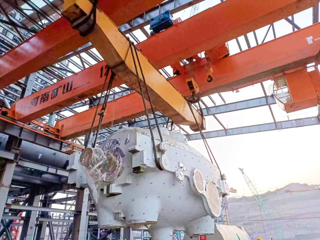
34 Double-Girder Cranes for Chongqing Panhua

Henan Mine Crane supplied 34 double-girder overhead cranes for Chongqing Panhua Sheet’s intelligent hot-rolling project in China. The package covered crane capacities from 10 t to 100 t across the project.

View the Panhua project
Overhead crane installed in a steel hot rolling mill
34 Double-Girder Cranes for Chongqing Panhua.

Two 120 t Double-Girder Cranes for Morowali

Henan Mine Crane supplied two 120 t new-design double-girder overhead cranes for a thermal-power construction project at Tsingshan Industrial Park in Morowali, Indonesia. The cranes were supplied for lifting work during construction of three 380 MW generating units.

View the Morowali project
Overhead crane handling a thermal power plant installation component
Two 120 t Double-Girder Cranes for Morowali.

Double girder crane buying questions

Which double girder overhead crane is right for a workshop?

For general hook lifting, compare QD and KSQ winch-trolley cranes with LH and KSSL electric-hoist bridges. Start with the maximum suspended load, crane span, useful hook height and lifts per shift. Consider two trolleys when a long component needs two lifting points. The model code follows the handling task, not the other way around.

What is the difference between a double girder EOT crane and a bridge crane?

Double girder EOT crane and double girder overhead bridge crane are common terms for the same basic two-girder bridge arrangement. The names alone do not identify the hoisting mechanism, duty or supplied equipment. Check whether the offer uses an electric hoist or a built-up winch trolley and compare the complete configuration.

When should I choose double girder instead of single girder?

Compare the layouts at the same required load, span, hook height and duty. A double-girder arrangement may suit a heavier handling task, a trolley above the girders or multiple lifting points. Building clearances, runway wheel loads and maintenance access also matter. There is no single capacity threshold that decides every project.

Should I choose an electric-hoist crane or a winch-trolley crane?

An electric-hoist bridge uses a packaged hoist on its trolley. A winch-trolley arrangement carries a built-up lifting mechanism on a trolley frame. Compare the rated load and duty together with hoisting speeds, usable hook height, maintenance access and the required lifting attachment. Ask for both arrangements if either could meet the task.

Can two trolleys lift the same component?

Yes, where the crane is configured and approved for the combined lift. State the component length, centre of gravity, lifting points and minimum and maximum hook spacing. The technical offer must define each trolley rating, the permitted combined load and the coordinated operating functions; do not add two individual ratings to assume a tandem capacity.

Does the capacity include a grab, magnet or lifting beam?

The selected rating must cover the complete suspended load. For a grab, account for grab self-weight and material density when assessing useful payload. For magnets, carrier beams and clamps, confirm the attachment weight and the compatible material or workpiece. Compare separate operating-mode ratings on a grab-and-magnet or grab-and-hook crane.

What should a double girder crane quotation include?

Ask for an itemized scope covering the bridge, end carriages, hoist or winch trolley, controls and electrical equipment. Confirm the status of runway rails, beams and columns, power supply systems, packing, freight, installation and commissioning. The offer should also identify drawings, manuals, inspection records, destination documents, warranty terms and spare-parts arrangements.

What details are enough to request a price?

Send the maximum load, approximate span, required lifting height and destination, with a short description of what you lift. Include the attachment and operating shifts if known. A workshop sketch or photograph is helpful, but you can start an enquiry before every dimension is finalized. Special environments and delivery or installation needs can be developed with the technical proposal.

Compare the range

Double girder crane specification comparison

Compare load, span, duty and handling task across the 39 model families. Select a full product name to open its details; each product card above also contains the complete specification table.

Swipe across the table to compare specifications.

Product / model Capacity Span / working width Working class Typical handling task
Double Girder Hook Overhead Crane (QD) 5 / 10 / 16/3.2 / 20/5 / 32/5 / 50/10 t; larger engineered options to 450/80 t 5–50 t: 10.5–31.5 m; larger cranes use capacity-specific spans A5–A6 standard selections; slow-speed A3 options General manufacturing, assembly and heavy-equipment handling
Manual Double Girder Overhead Crane (SQ) 5 / 10 / 16 / 20 t 10–17 m Occasional manual handling; selected for lifting frequency and operating effort Occasional maintenance and storage lifting without powered crane motion
Modular Double Girder Overhead Crane (KSQ) Custom rating for workpiece plus lifting gear Custom rail-centre span and runway length Selected for load spectrum and lifts per shift General production and precise positioning
Double Trolley Overhead Crane (QE) 5+5 / 10+10 / 16+16 t 10.5–31.5 m in 3 m steps A5 or A6 Long loads and paired lifting
Modular Double Trolley Overhead Crane (KSQE) Each trolley rated for its maximum reaction; combined lifting rating specified separately Custom rail-centre span to the production bay Selected from load spectrum, lifts per hour and operating shifts Long materials and balanced turning
Three Trolley Overhead Crane for Paper Mills (QES) Three individual trolley ratings and approved combined-load cases Custom rail-centre span to the production bay Selected from load spectrum, lifts per hour and operating shifts Paper-making and long-load processes
Electric Hoist Double Girder Overhead Crane (LH) 3 / 5 / 10 / 16 / 20 t 10.5–31.5 m in 3 m steps for the listed configurations A3–A4 for the listed configurations General production handling
European Type Double Girder Hoist Crane (KSSL) Custom rating for the complete suspended load Custom rail-centre span to the production bay Selected from load spectrum, lifts per hour and operating shifts Assembly and production workshops
Double Trolley Electric Hoist Overhead Crane (LHE) Two separate trolley ratings, matched to the actual load distribution Custom rail-centre span to the production bay Selected from load spectrum, lifts per hour and operating shifts Long components and paired lifts
Low Headroom Double Trolley Hoist Crane (LHEA) Custom individual-trolley and combined-load ratings Custom rail-centre span to the production bay Selected from load spectrum, lifts per hour and operating shifts Multiple workstations
Double Trolley Electric Hoist Overhead Crane (KSSLE) Custom per-trolley and combined lifting ratings Custom rail-centre span to the production bay Selected from load spectrum, lifts per hour and operating shifts Long and unbalanced loads
Three Trolley Electric Hoist Overhead Crane (KSSLS) Three individual hoist ratings and permitted combined lifting cases Custom rail-centre span to the production bay Selected from load spectrum, lifts per hour and operating shifts Paper-production equipment
Electromagnetic Overhead Crane (QC) 5 / 10 / 16 t magnet; 16/3.2 / 20/5 / 32/5 t main/auxiliary 10.5–31.5 m in 3 m steps A6 for the listed configurations Steel plate, profiles and magnetic stock
Electromagnetic Carrier Beam Overhead Crane (QL) 10+10 / 12.5+12.5 / 13.5+13.5 t listed selections 28.5 / 28.5 / 31.5 m, in the same capacity order A6 / A7 / A7, in the same capacity order Long steel stock
Upper Rotating Magnetic Beam Overhead Crane (YC) 5+5–25+25 t family; configured to beam and steel load 10.5–31.5 m family A6–A7 family Billets, plate and bar handling
Lower Rotating Magnetic Beam Overhead Crane (QLC) Custom rating including magnetic beam and steel payload Custom rail-centre span to the production bay Selected from load spectrum, lifts per hour and operating shifts Steel mills and stockyards
Lower Rotating Carrier Beam Overhead Crane (QJ) Custom rating for steel, carrier beam and attachment Custom rail-centre span to the production bay Selected from load spectrum, lifts per hour and operating shifts Steel stock and coils
Double Girder Grab Overhead Crane (QZ) 5 / 10 / 16 / 20 t; rated load includes grab self-weight 5/10 t: 10.5–31.5 m; 16/20 t: 16.5–31.5 m A6 for the listed configurations Bulk stockyards and process bays
Grab and Magnet Double Girder Overhead Crane (QP) Grab/magnet modes: 5/5 / 10/10 / 16/16 t 5/5 t: 10.5–31.5 m; 10/10 t: 13.5–31.5 m; 16/16 t: 19.5–31.5 m A6 for the listed configurations Mixed bulk and steel handling
Grab and Hook Double Girder Overhead Crane (QEN) Separate hook- and grab-mode ratings including attachment tare Custom rail-centre span to the production bay Selected from load spectrum, lifts per hour and operating shifts Mixed workshop and bulk handling
Hook, Grab and Magnet Overhead Crane (QS) Separate hook, grab and magnet ratings including attachment tare Custom rail-centre span to the production bay Selected from load spectrum, lifts per hour and operating shifts Frequent material-type changes
Explosion-Proof Electric Hoist Overhead Crane (LHB) Custom load rating for the protected electric-hoist package Custom rail-centre span to the production bay Selected from load spectrum, lifts per hour and operating shifts Hazardous industrial areas
Explosion-Proof Double Girder Overhead Crane (QB) 5 / 10 / 16/3.2 / 20/5 / 32/5 / 50/10 t 10.5–31.5 m in 3 m steps A3–A4 for the listed configurations Chemical, oil, gas and dust sites
Cleanroom Explosion-Proof Overhead Crane (ZJJB) Custom rating for the clean and explosion-protected lifting package Custom rail-centre span to the production bay Selected from load spectrum, lifts per hour and operating shifts Semiconductor and precision chemical bays
Double Trolley Explosion-Proof Overhead Crane (QBE) Two individual trolley ratings plus approved tandem capacity Custom rail-centre span to the production bay Selected from load spectrum, lifts per hour and operating shifts Long loads in classified areas
Insulated Overhead Crane (QY) 5 / 10 / 16/3.2 / 20/5 t 10.5–31.5 m in 3 m steps A6 for the listed configurations Electrolytic and energized-process bays
Double Trolley Insulated Overhead Crane (QYE) Two individual trolley ratings from actual lifting-point reactions Custom rail-centre span to the production bay Selected from load spectrum, lifts per hour and operating shifts Long loads near energized equipment
Metallurgical Electric Hoist Overhead Crane (LHY) Custom rated load including ladle and lifting equipment Custom rail-centre span to the production bay Selected from load spectrum, lifts per hour and operating shifts Molten-metal handling in foundry and metallurgical workshops
Slab Handling Overhead Crane (YB) Custom load rating for slab plus gripping attachment Custom rail-centre span to the production bay Selected from load spectrum, lifts per hour and operating shifts Continuous casting and slab yards
Quenching Overhead Crane (YH) Custom rating for workpiece, fixture and retained fluid loads Custom rail-centre span to the production bay Selected from load spectrum, lifts per hour and operating shifts Heat treatment
Charging Box Overhead Crane (YX) Custom rating for fully charged box and lifting device Custom rail-centre span to the production bay A6–A7 family Smelting material transfer
Double Girder Ladle Casting Crane (YZ) 100/32 / 125/32 / 140/40 / 160/50 / 200/50 t listed selections 19 / 22 / 25 m according to selected capacity A7 Molten-metal transfer and pouring
Metallurgical Hook Overhead Crane (YZD) 5 / 10 / 16/3.2 / 20/5 / 32/5 / 50/10 / 74/20 t 5–50 t: 10.5–31.5 m; 74/20 t: 13.5–31.5 m A7 listed selections; A6–A8 engineered family Molten-metal handling
Multi-Point Double Girder Underhung Crane (LHDX) Custom rated load distributed across multiple suspension tracks Custom multi-track working width and support spacing Selected from load spectrum, lifts per hour and operating shifts Large-span roof-supported bays
Double Girder Underhung Rail-Transfer Crane (KSX) Custom rated load for maintenance equipment and lifting gear Custom transfer-rail and bridge geometry Selected from load spectrum, lifts per hour and operating shifts Power-station and cross-bay transfer
Container Overhead Crane (CQJ) 30–65 t 18–35 m Matched to container throughput and operating hours Container transfer and stacking
Double Girder Underhung Crane (KSQX) Custom rated load for suspended double-girder structure Custom working width and support spacing Selected from load spectrum, lifts per hour and operating shifts Column-free production floor
Zinc Pot Service Overhead Crane (QDXG) Custom rating for empty zinc pot and maintenance lifting gear Custom runway span with required trolley cantilever reach Selected from load spectrum, lifts per hour and operating shifts Hot-dip galvanizing maintenance
Anode Block Stacking Crane (YDJ) Custom rating for the selected anode-block batch and clamp Custom storage-bay span and stack coverage Selected from load spectrum, lifts per hour and operating shifts Anode-block stores

The ranges above are selection references. Capacity, span, lifting height and duty are confirmed together. Listed paired or mode-specific ratings must be read with their corresponding equipment and operating case; they are not automatically additive.

Get a double girder overhead crane quote

Send the maximum load, approximate span, required lifting height and project location. Add the material or workpiece, lifting attachment and shifts if known. A workshop sketch is helpful, but you can start with the information you already have.

Your technical offer will identify the crane configuration, documents, delivery terms, installation scope and support arrangements for the project.

Request a quotation