
Separate the masses
Keep the bridge mass separate from the trolley and suspended load to avoid counting a component twice.
Bridge cranes for workshops and production lines.
Explore Overhead Cranes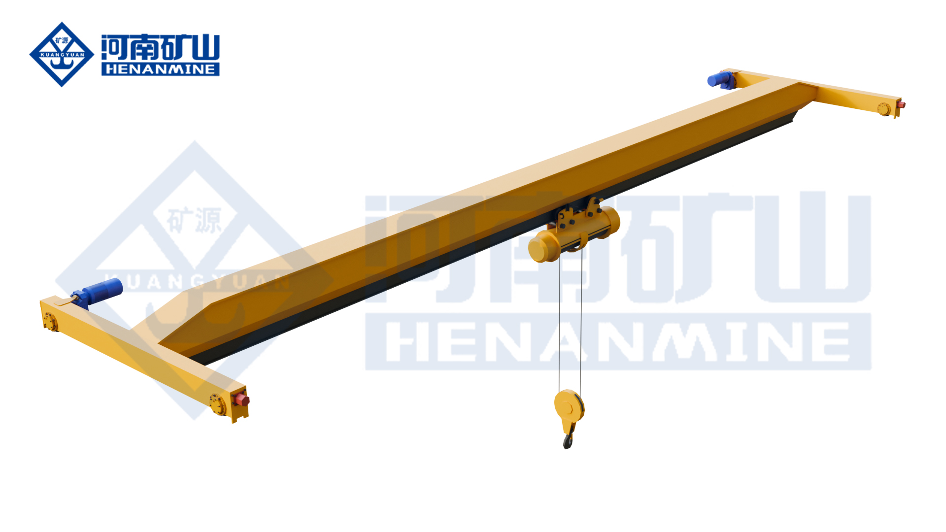
Ground-supported lifting for yards and construction.
Explore Gantry Cranes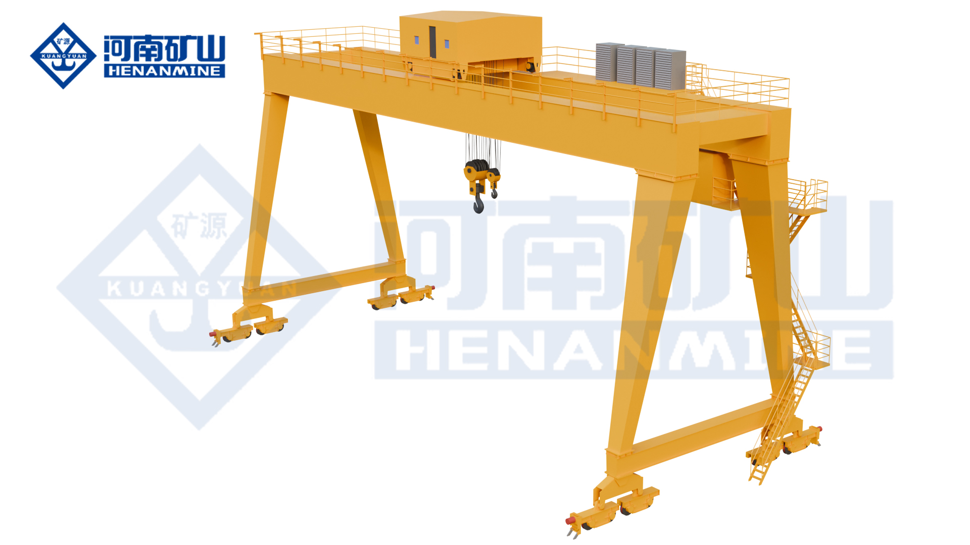
Wire rope and chain hoists for lifting points and cranes.
Explore Electric Hoists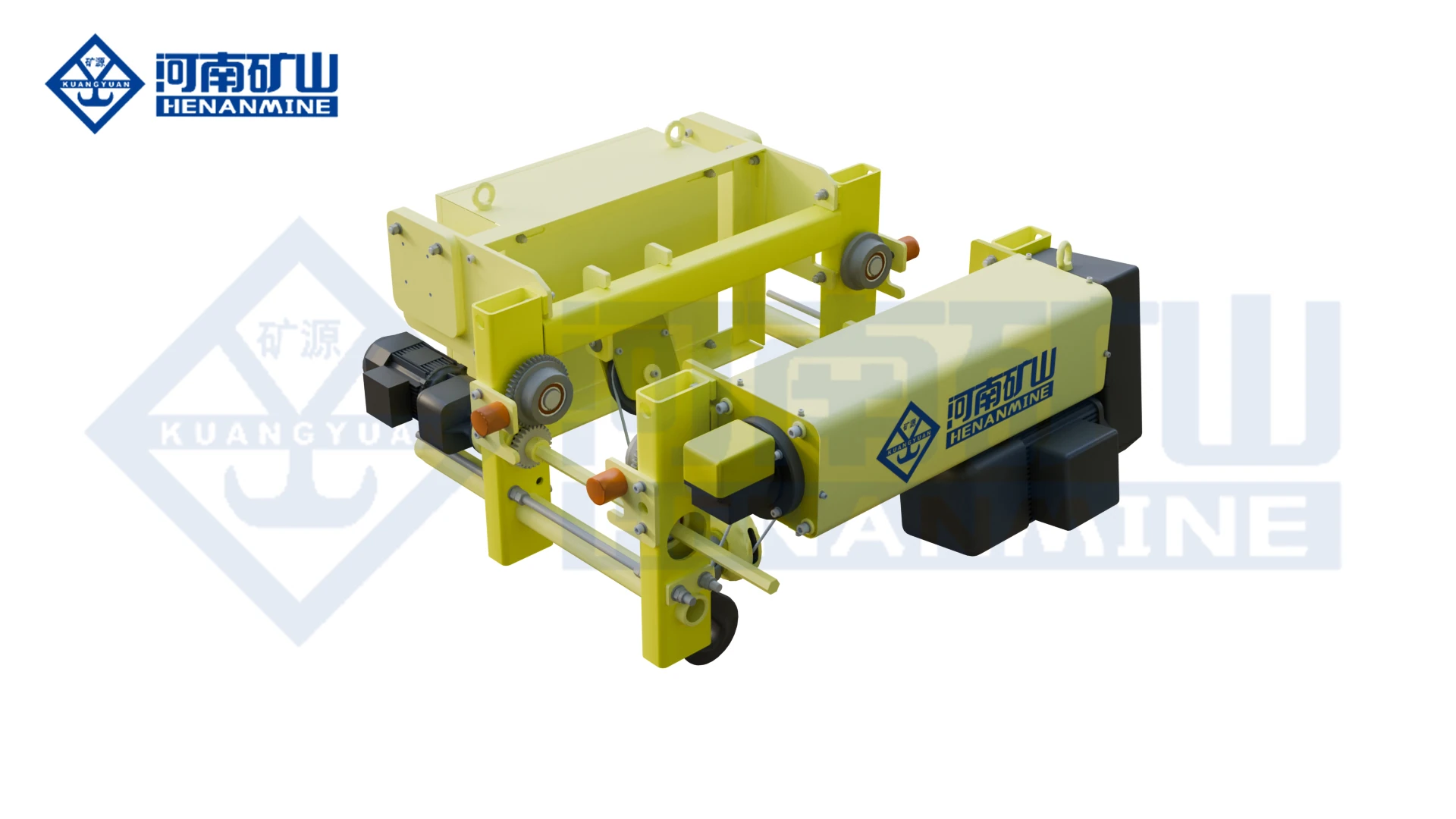
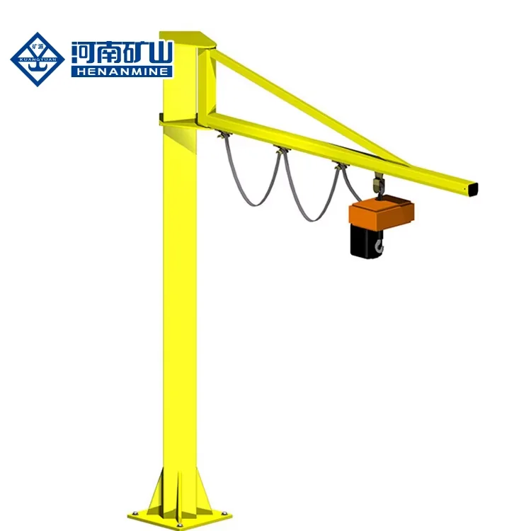
Wire rope lifting and pulling with a powered drum.
Explore Electric Winches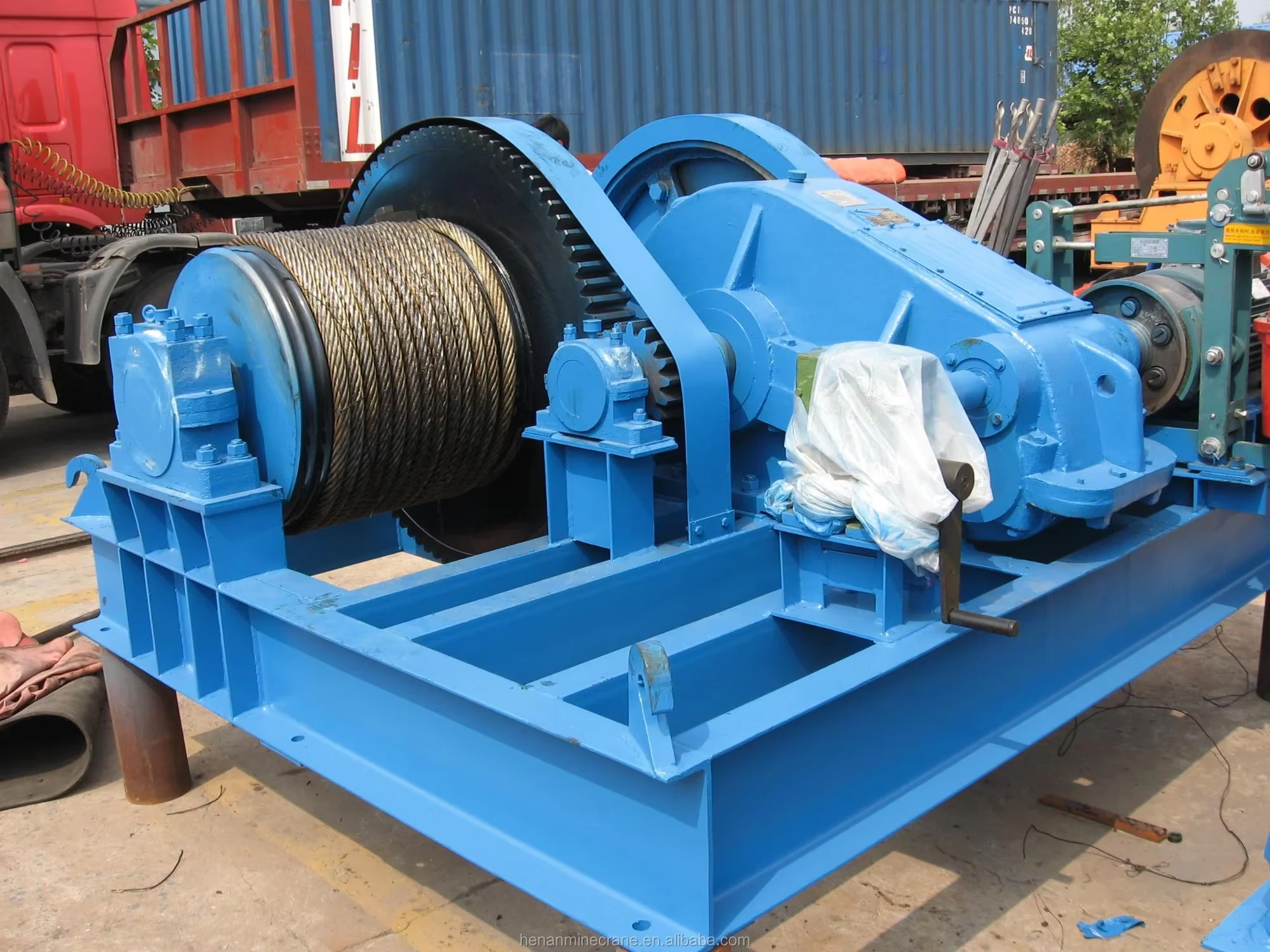
Grab buckets, magnets and hooks for your load.
Explore Lifting Attachments & Grabs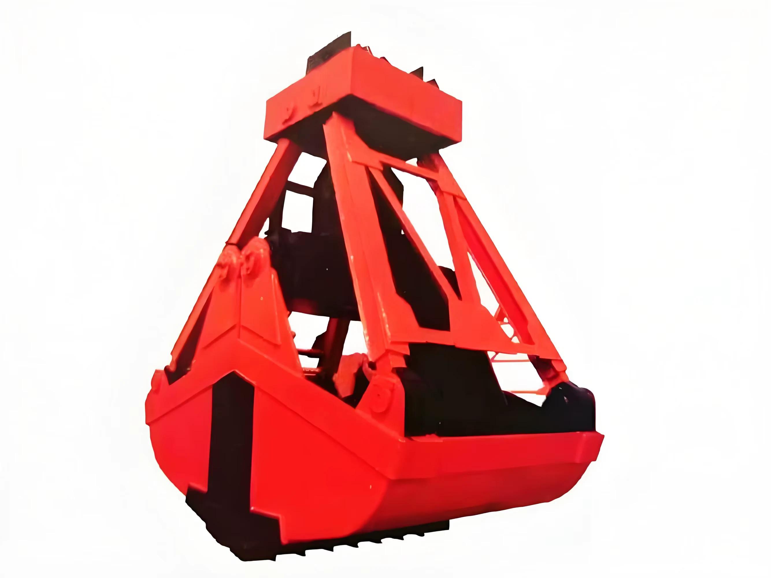
Mobile handling for containers, precast and yard loads.
Explore Rubber-Tired Gantry Cranes & Straddle Carriers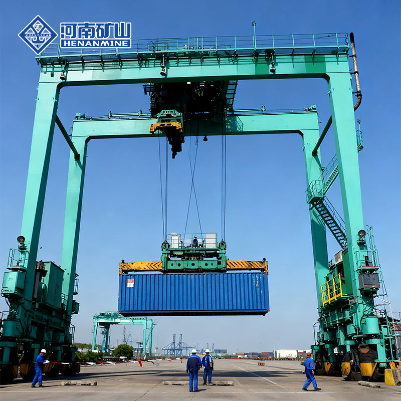
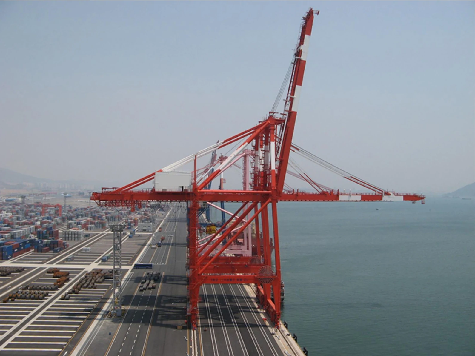
Lift and move vessels through boatyards and marinas.
Explore Marine Travel Lifts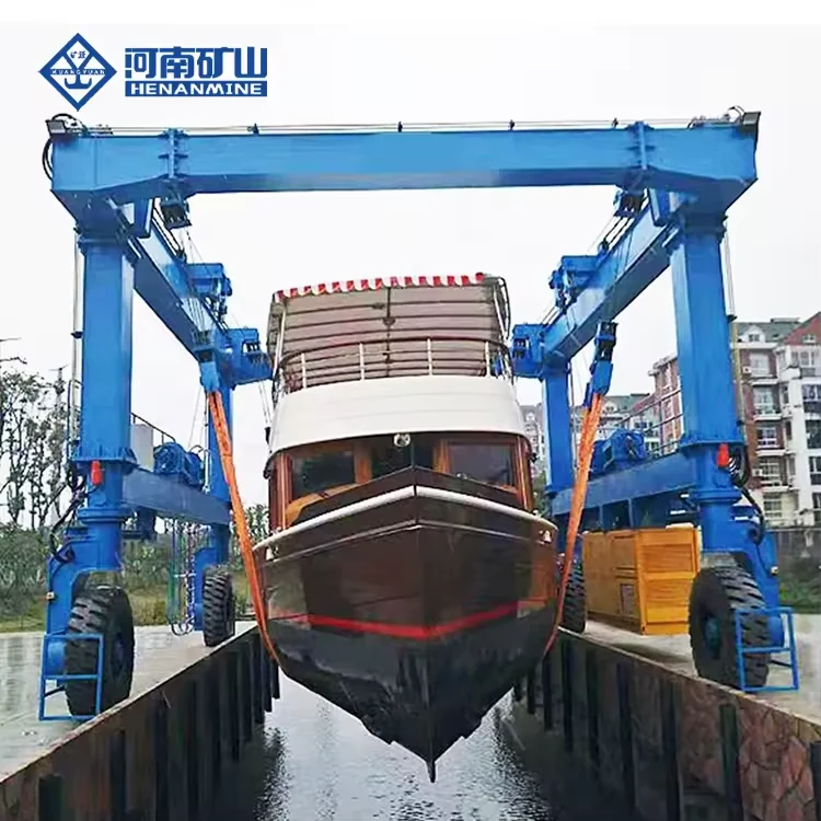
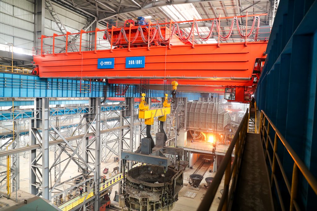
Ladle, slab, scrap and coil handling across steel production.
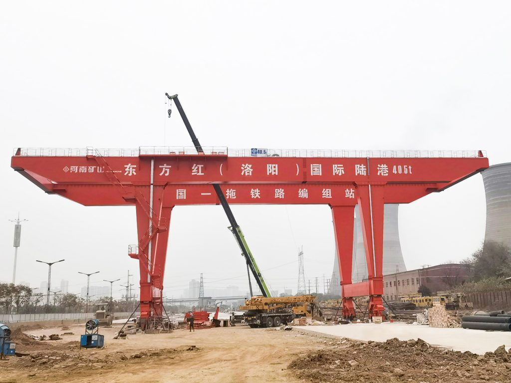
Container stacking and cargo transfers across terminals and rail.
Turbine installation, powerhouse maintenance and wind equipment assembly.
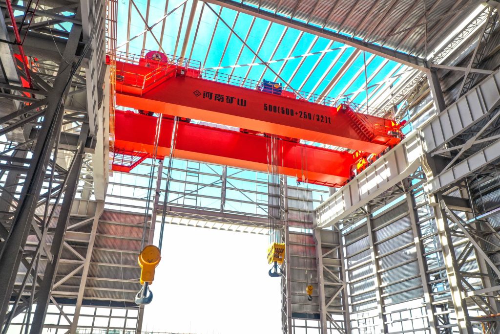
Controlled component transfer and positioning for precision assembly.
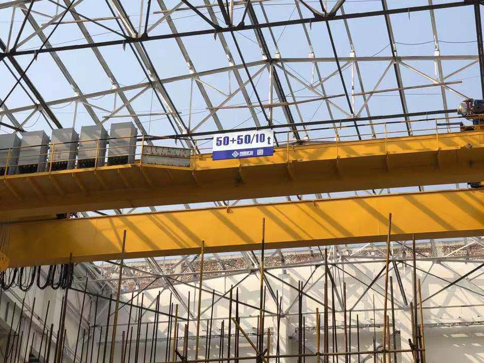
Heavy fabrication, production lifting and factory crane automation.
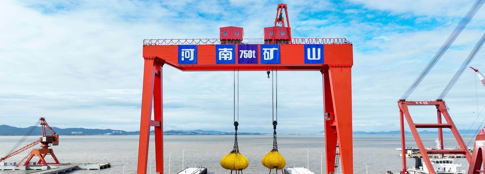
Process lifting for smelters, carbon blocks and anode materials.
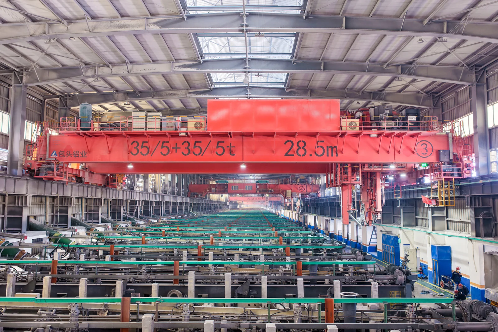
Clean lifting and classified protection for sensitive process areas.
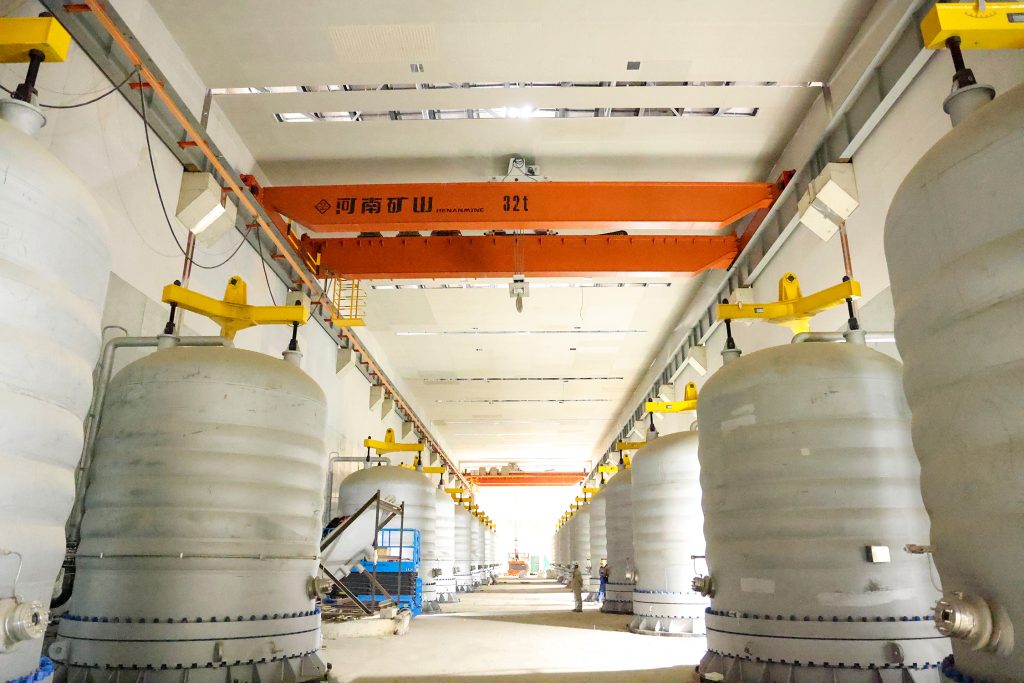
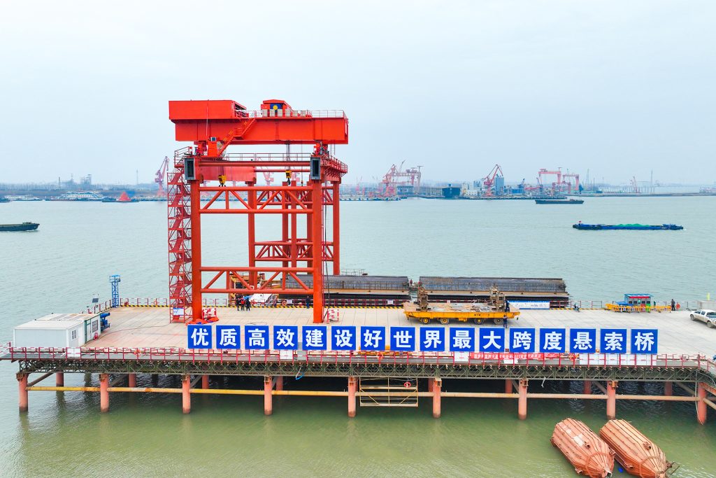
Bridge fabrication, metro construction and ship block assembly.
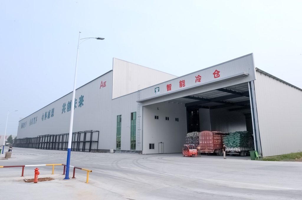
Automated storage and retrieval for plates, cables and bins.
Follow project dispatches, crane engineering and factory acceptance.
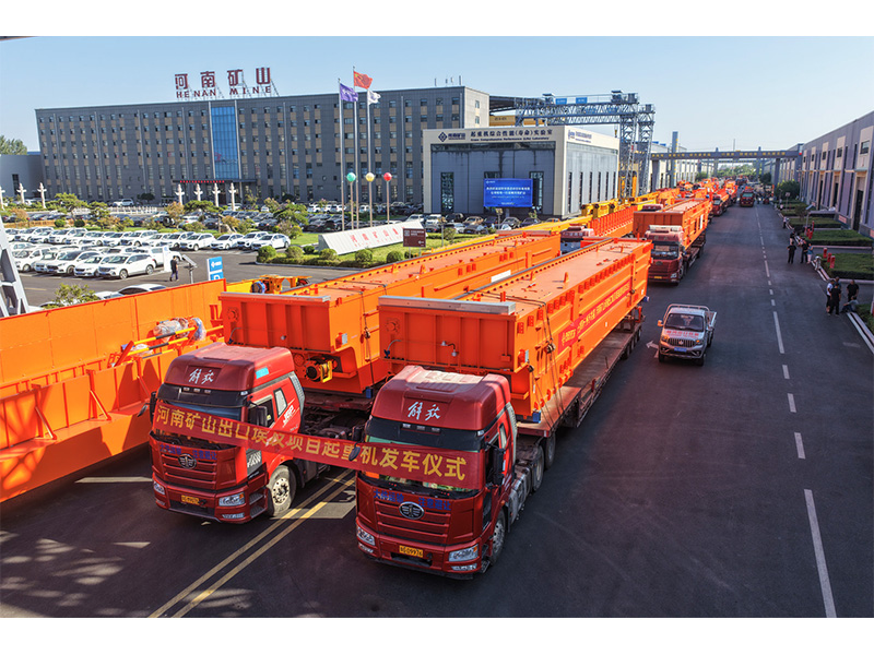
Dispatch, installation and equipment in service
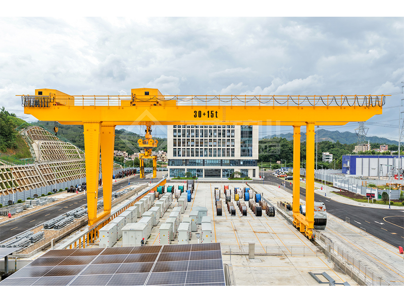
Crane configurations and handling technology
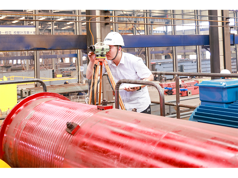
Factory inspections, acceptance and test programmes

Company developments, people and community programmes
Estimate how trolley position transfers static load between the two runways before requesting certified wheel-load data.
Keep the bridge mass separate from the trolley and suspended load to avoid counting a component twice.
Measure its load line from the left runway support line across the bridge.
Read each runway reaction, then the ideal equally shared wheel loads for that side.
20 m span, 15,000 kg bridge, 2,000 kg trolley, 10,000 kg suspended load, trolley 2 m from the left runway and two wheels per side.
Left and right runway reactions are about 179.462 kN and 85.318 kN. Ideal left wheel load is 89.731 kN per wheel.
The largest ideal wheel load changes as the trolley moves across the span.
The two runway reactions add up to the complete entered static gravity load.
Equal sharing is a simplifying assumption. Actual end-carriage geometry, longitudinal eccentricity, dynamics and load combinations may increase individual wheel actions.
Using the complete crane mass as bridge mass and then adding the trolley mass again.
R_left = g[m_bridge/2 + (m_trolley + m_load)(L−x)/L]
R_right = g[m_bridge/2 + (m_trolley + m_load)x/L]
F_wheel = R_side / N_wheels
Request the crane supplier’s wheel loads, spacings, load combinations and horizontal actions. This model is a preliminary static comparison.
Actual loads depend on longitudinal centres of gravity, end-carriage arrangement, stiffness and operating actions, which this transverse model omits.