
Choose the section that matches your drawing
Choose solid rectangle, rectangular hollow section, doubly symmetric I section, solid circle or circular hollow section. The I-section option assumes equal top and bottom flanges.
Bridge cranes for workshops and production lines.
Explore Overhead Cranes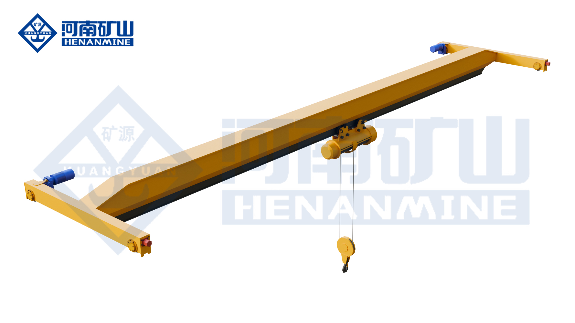
Ground-supported lifting for yards and construction.
Explore Gantry Cranes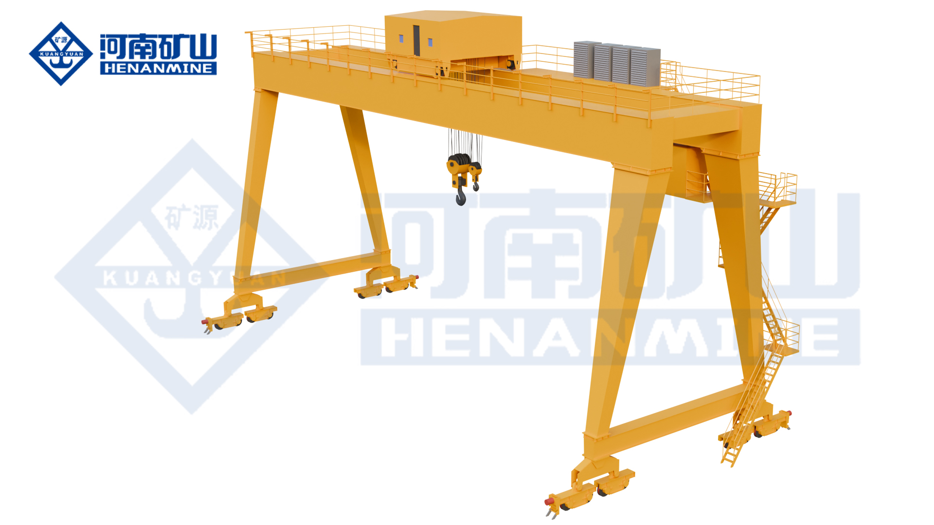
Wire rope and chain hoists for lifting points and cranes.
Explore Electric Hoists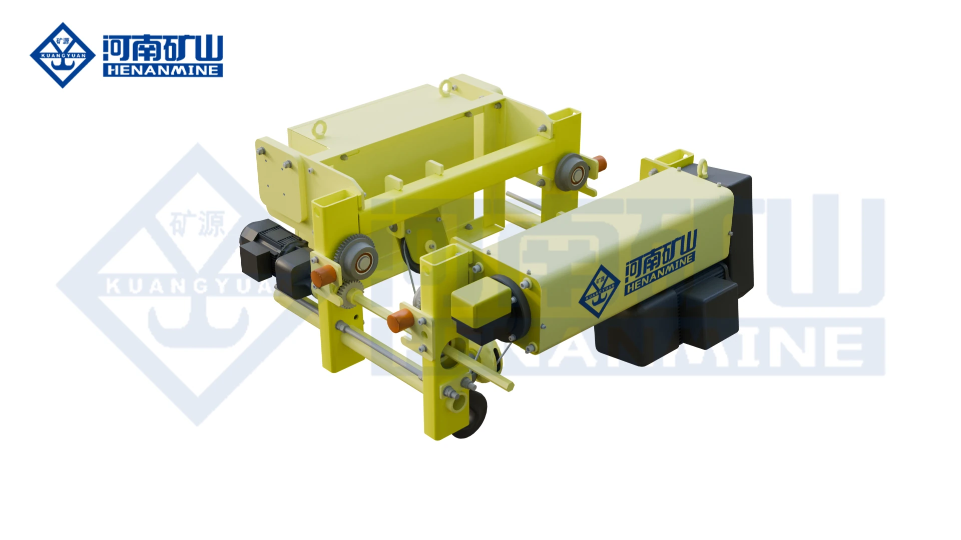
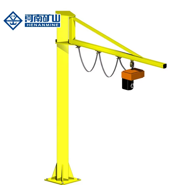
Wire rope lifting and pulling with a powered drum.
Explore Electric Winches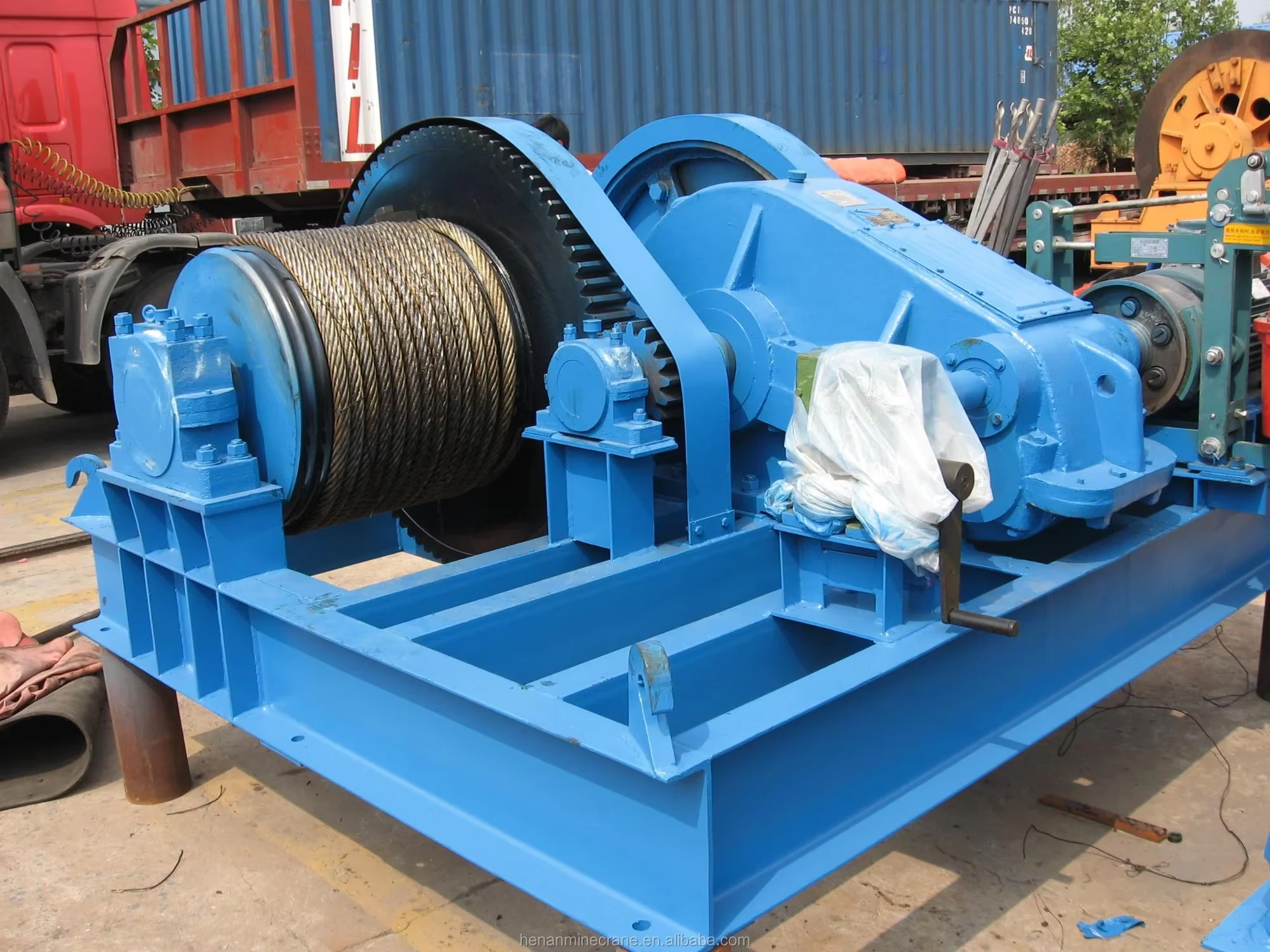
Grab buckets, magnets and hooks for your load.
Explore Lifting Attachments & Grabs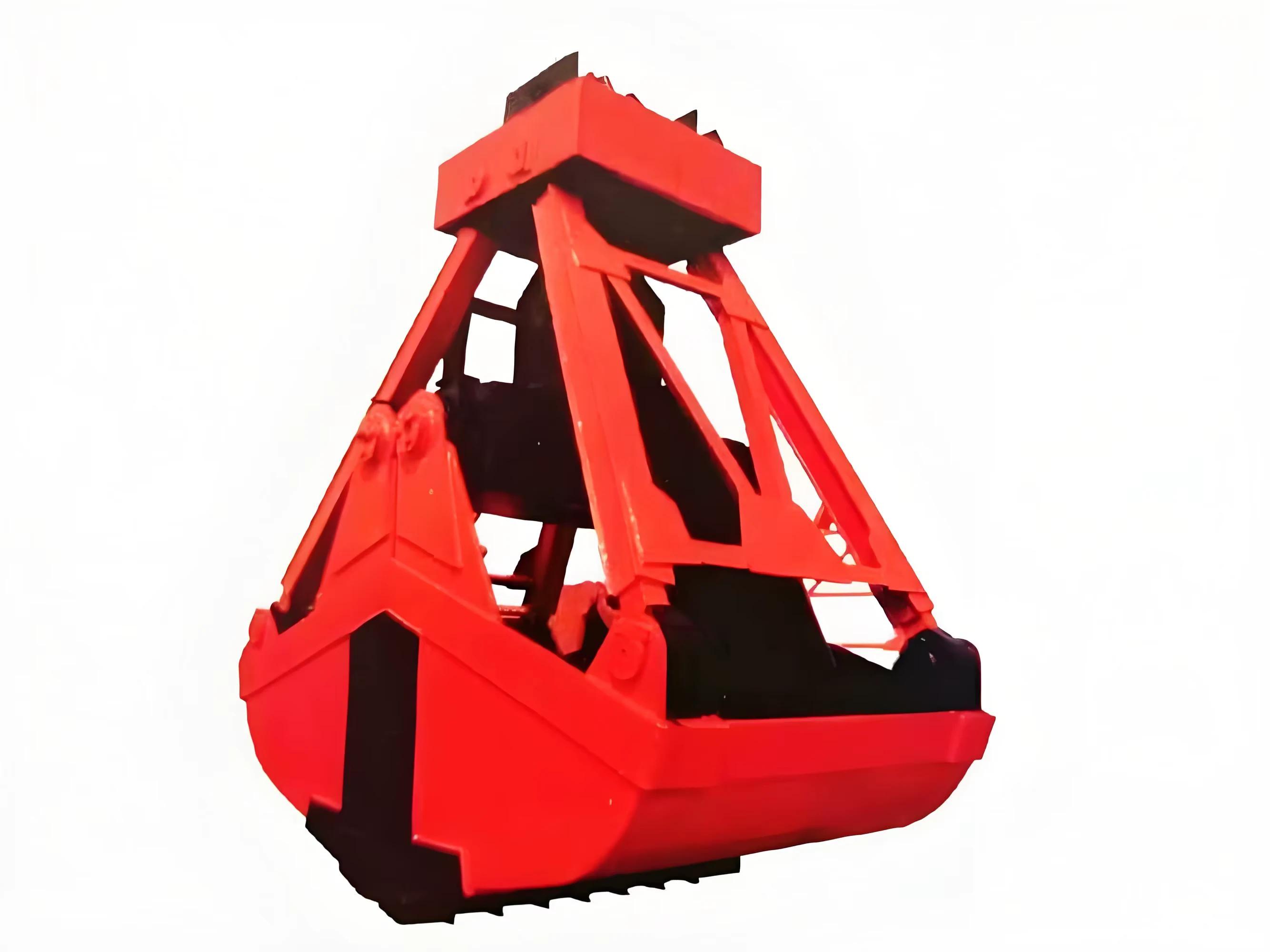
Mobile handling for containers, precast and yard loads.
Explore Rubber-Tired Gantry Cranes & Straddle Carriers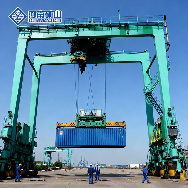
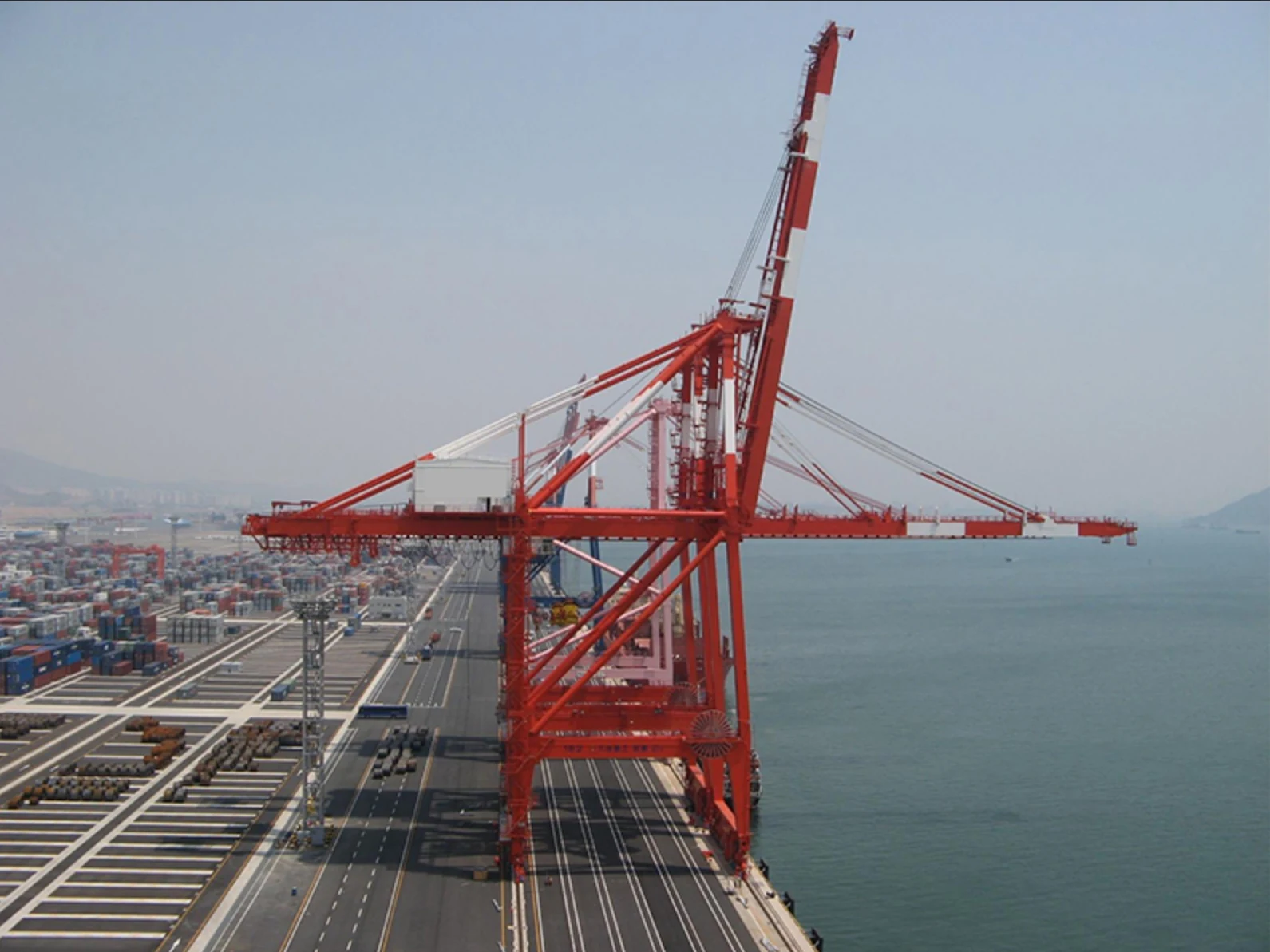
Lift and move vessels through boatyards and marinas.
Explore Marine Travel Lifts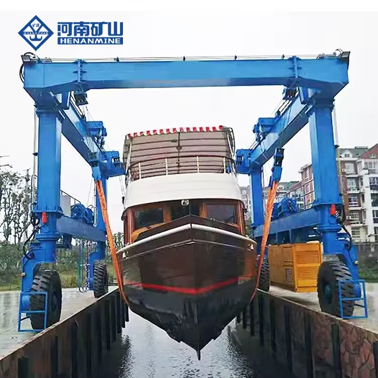
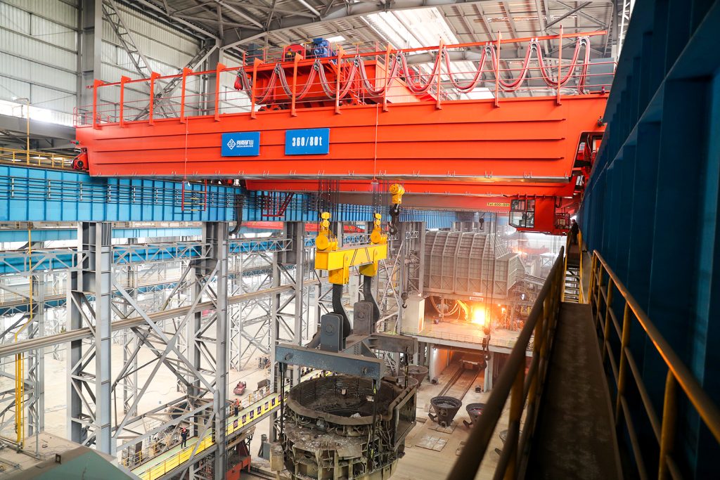
Ladle, slab, scrap and coil handling across steel production.
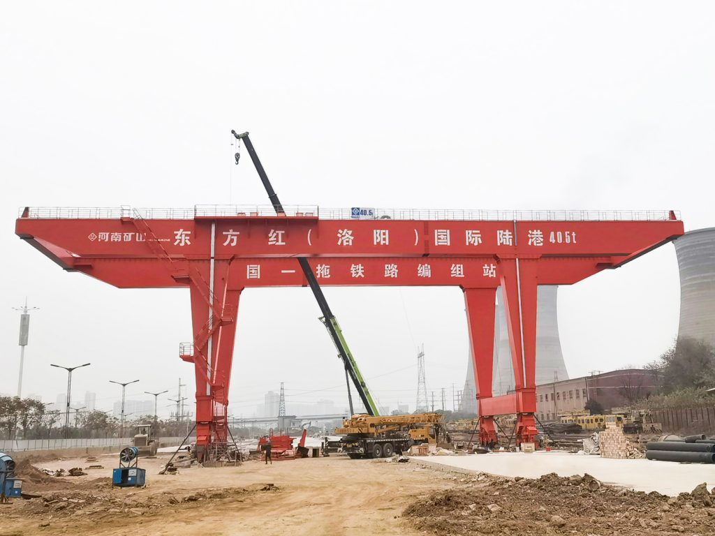
Container stacking and cargo transfers across terminals and rail.
Turbine installation, powerhouse maintenance and wind equipment assembly.
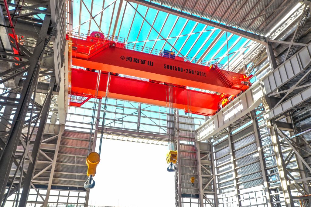
Controlled component transfer and positioning for precision assembly.
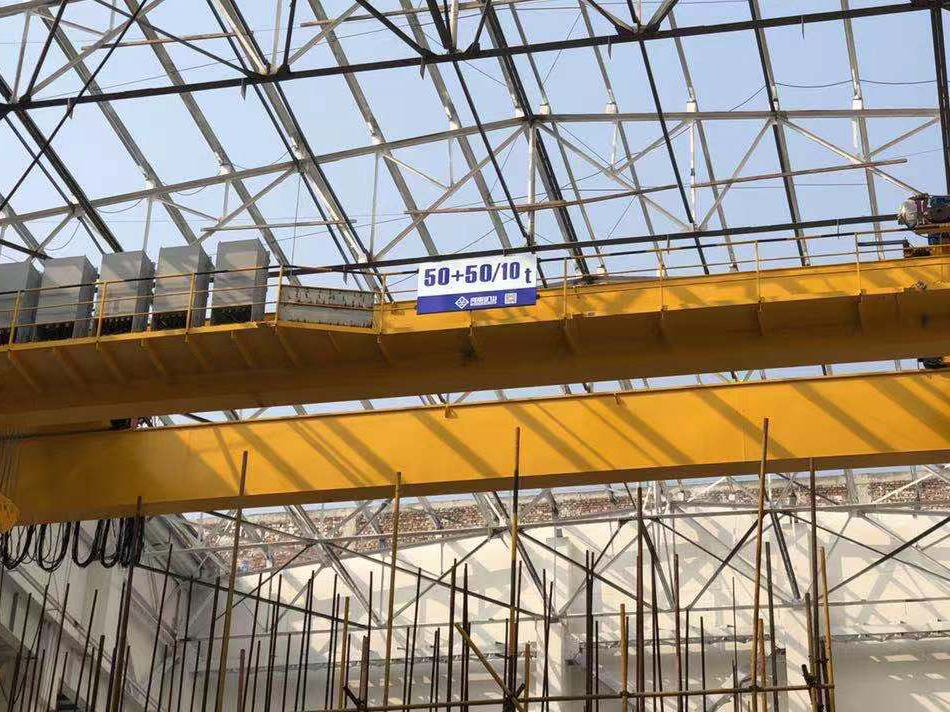
Heavy fabrication, production lifting and factory crane automation.
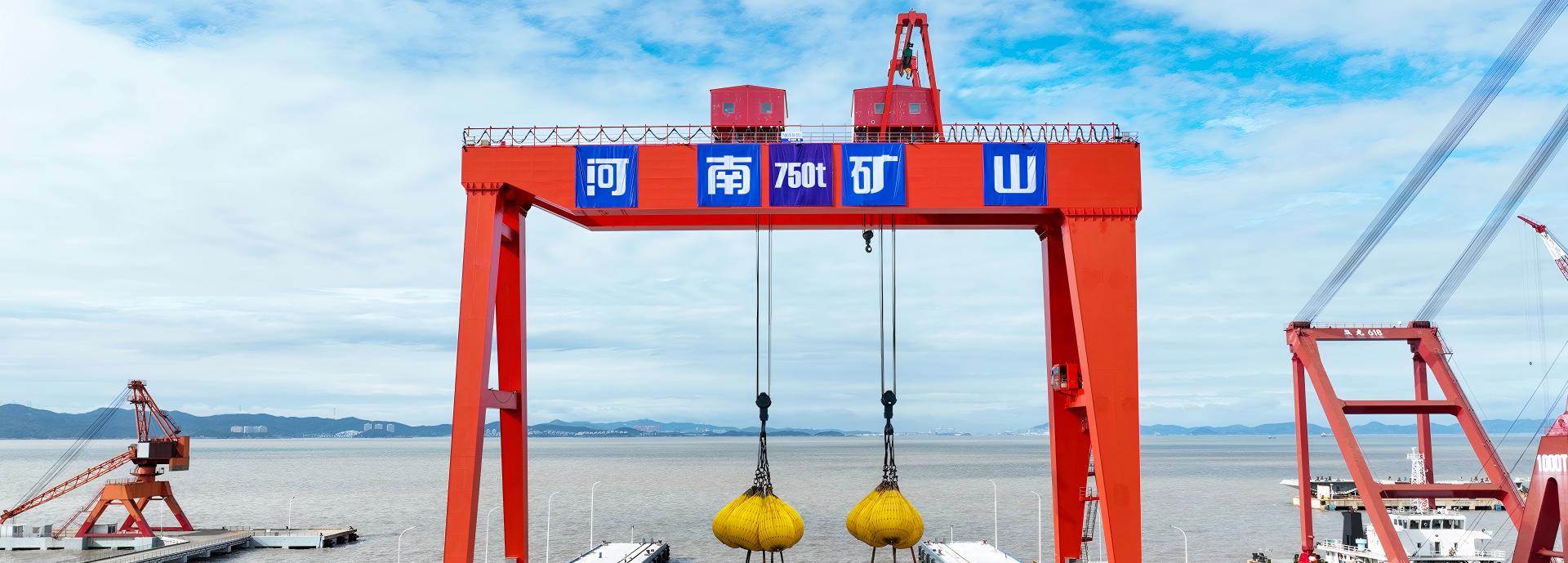
Process lifting for smelters, carbon blocks and anode materials.
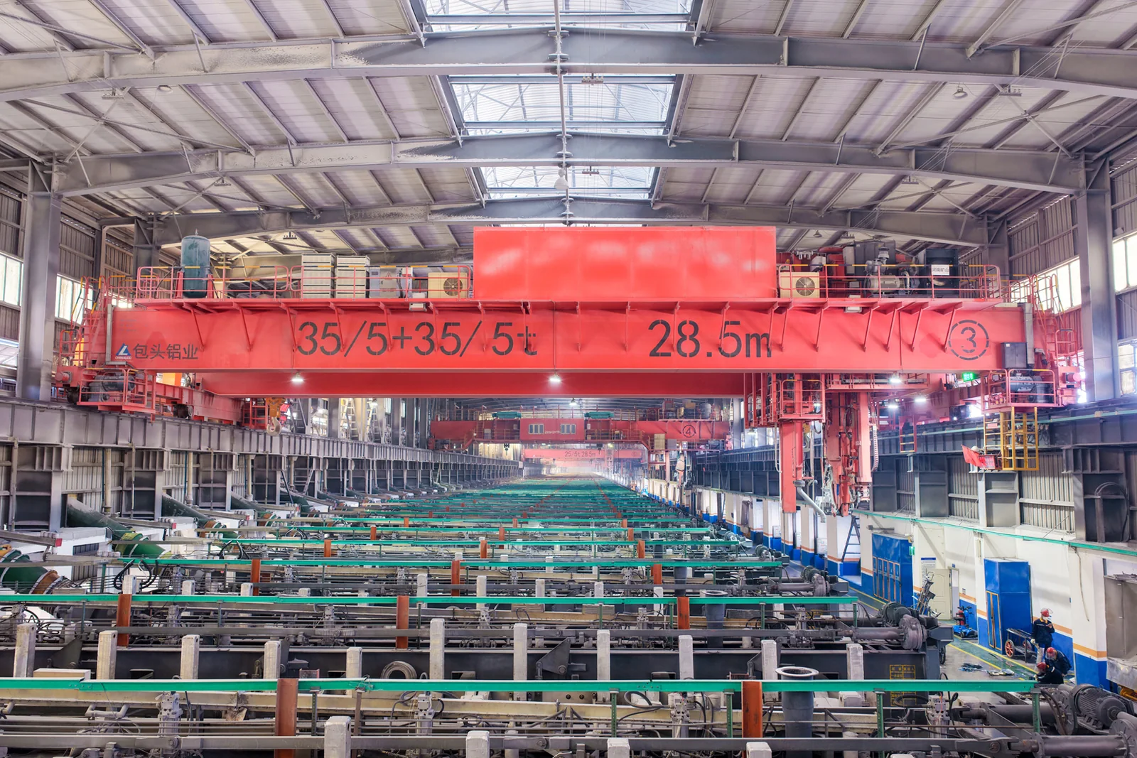
Clean lifting and classified protection for sensitive process areas.
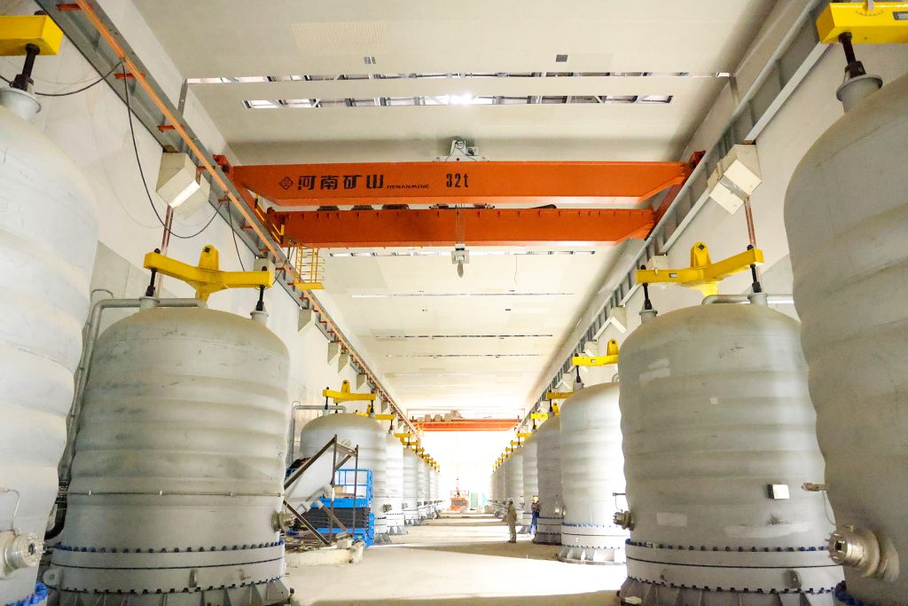
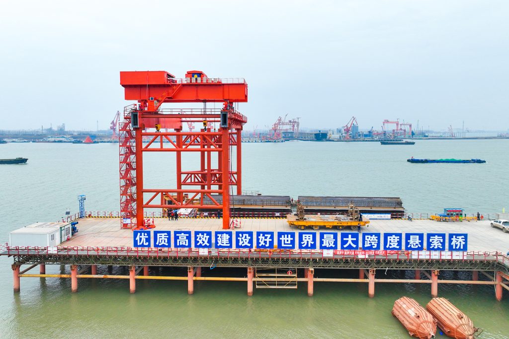
Bridge fabrication, metro construction and ship block assembly.
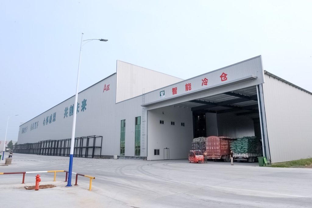
Automated storage and retrieval for plates, cables and bins.
Follow project dispatches, crane engineering and factory acceptance.
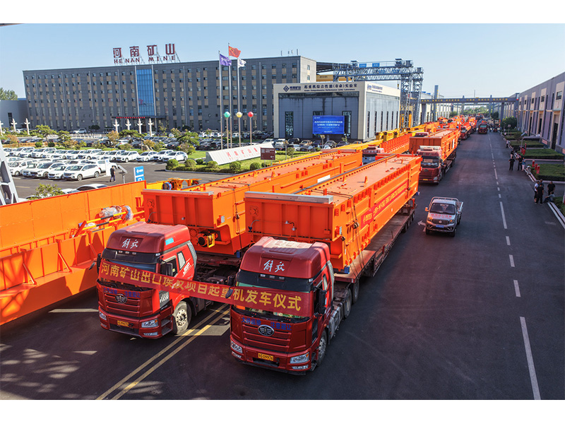
Dispatch, installation and equipment in service
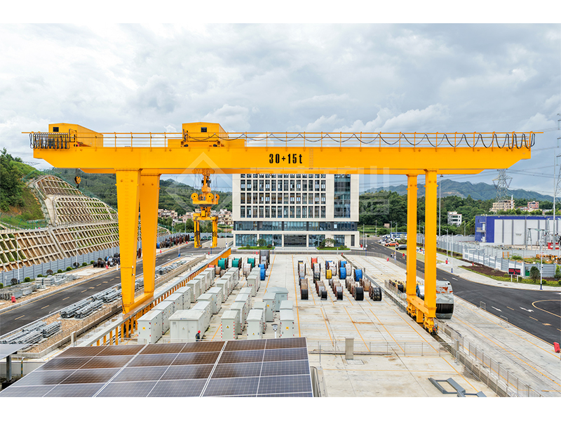
Crane configurations and handling technology
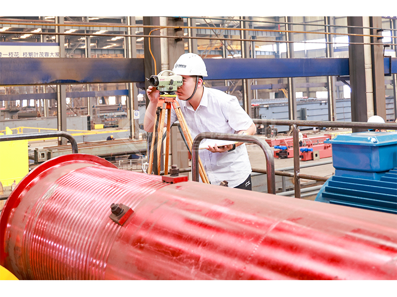
Factory inspections, acceptance and test programmes

Company developments, people and community programmes
Use this when comparing candidate beam sections or preparing geometric inputs for an elastic beam calculation. It calculates section geometry from dimensions; it does not convert a beam into a rated crane capacity.
Choose solid rectangle, rectangular hollow section, doubly symmetric I section, solid circle or circular hollow section. The I-section option assumes equal top and bottom flanges.
B is the outside width and H is the overall vertical height. Use t for a uniform hollow wall, tf for flange thickness, tw for web thickness, or D for outside diameter. Enter mm, not cm or m.
The x axis is horizontal through the centroid; y is vertical through the centroid. Read Ix for bending about x and Iy for bending about y, then carry the matching value and unit into your next calculation.
Shape rectangular hollow section; outside width B = 200 mm; vertical height H = 300 mm; uniform wall t = 10 mm.
Ix = 120,720,000 mm⁴; Iy = 63,920,000 mm⁴; area = 9,600 mm². The centroid is 100 mm from the left and 150 mm from the bottom. Zx = 804,800 mm³ and Zy = 639,200 mm³.
Area describes how much material lies in the section. The centroid locates its geometric centre within the outside bounding rectangle.
Ix and Iy are second moments of area about two different centroidal axes. They quantify geometric resistance to bending curvature, not the load the beam may carry.
Elastic section moduli Zx and Zy relate elastic bending moment to extreme-fibre bending stress. They are different from I: Z uses mm³, while I uses mm⁴.
Copying a catalogue value in cm⁴ into a field marked mm⁴. Multiply cm⁴ by 10,000 to obtain mm⁴. Also keep the section orientation: rotating a rectangle or box by 90° swaps its x- and y-axis properties.
Rectangle: Ix = B × H³ / 12; Iy = H × B³ / 12
Box: subtract the inner rectangle, width B−2t and height H−2t, from the outer rectangle
I section: Ix = [BH³ − (B−tw)(H−2tf)³] / 12
I section: Iy = [2tf B³ + (H−2tf)tw³] / 12; tf = flange thickness, tw = web thickness
Circle: Ix = Iy = πD⁴ / 64; tube: Ix = Iy = π[D⁴ − (D−2t)⁴] / 64
Elastic section modulus: Zx = Ix / extreme vertical distance; Zy = Iy / extreme horizontal distance
Multiply by 10,000: 1 cm⁴ = 10,000 mm⁴. For example, 12,072 cm⁴ equals 120,720,000 mm⁴. Do not use the factor of 10 that applies to a simple length.
No. Capacity also depends on span, loading, material, stability, deflection, fatigue, connections and the applicable design method. Ix is one geometric input to those checks.