
Represent the real load model
Use the form only when one simple span, one point force and a full-span uniform load reasonably represent the arrangement. Set an unused load to zero.
Bridge cranes for workshops and production lines.
Explore Overhead Cranes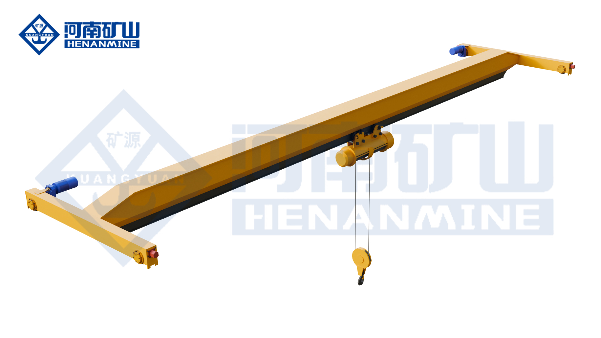
Ground-supported lifting for yards and construction.
Explore Gantry Cranes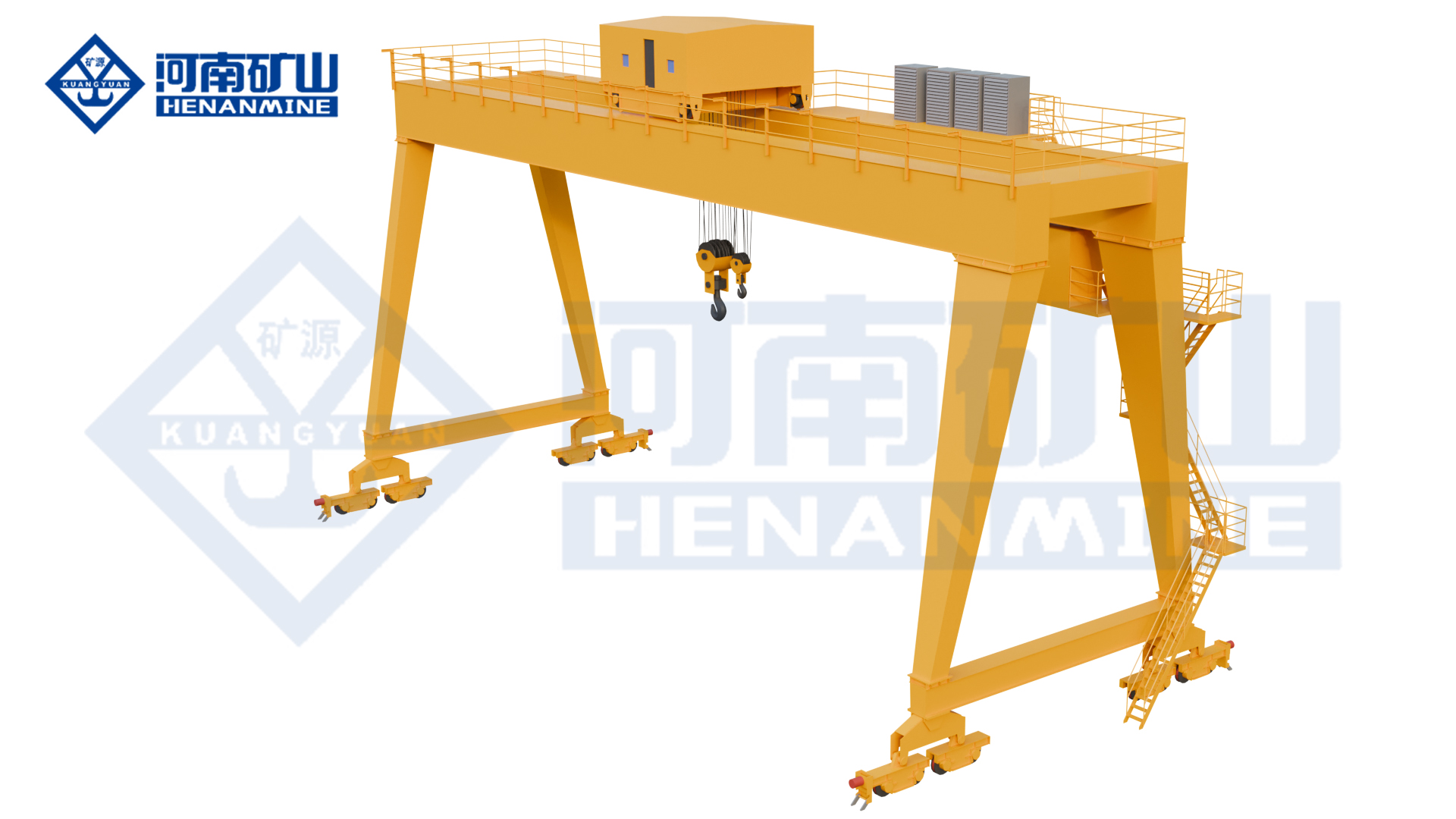
Wire rope and chain hoists for lifting points and cranes.
Explore Electric Hoists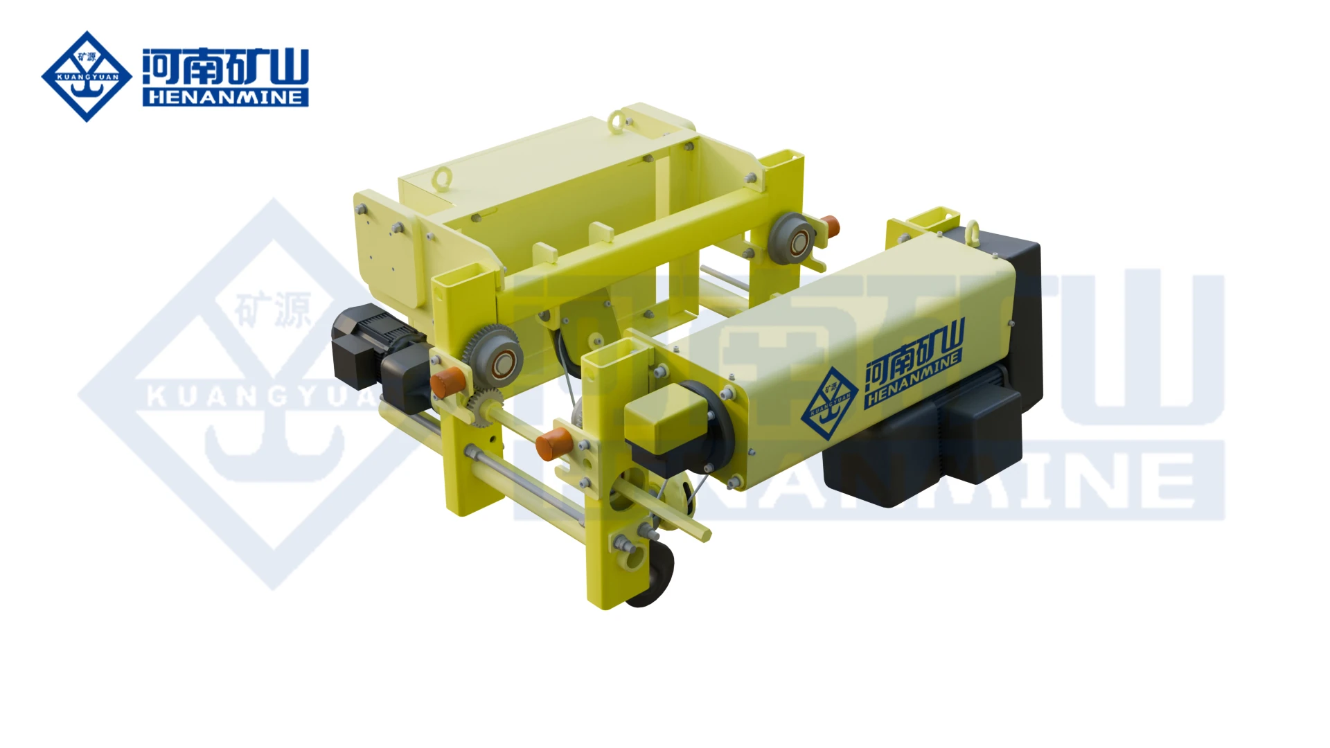
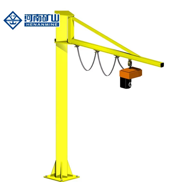
Wire rope lifting and pulling with a powered drum.
Explore Electric Winches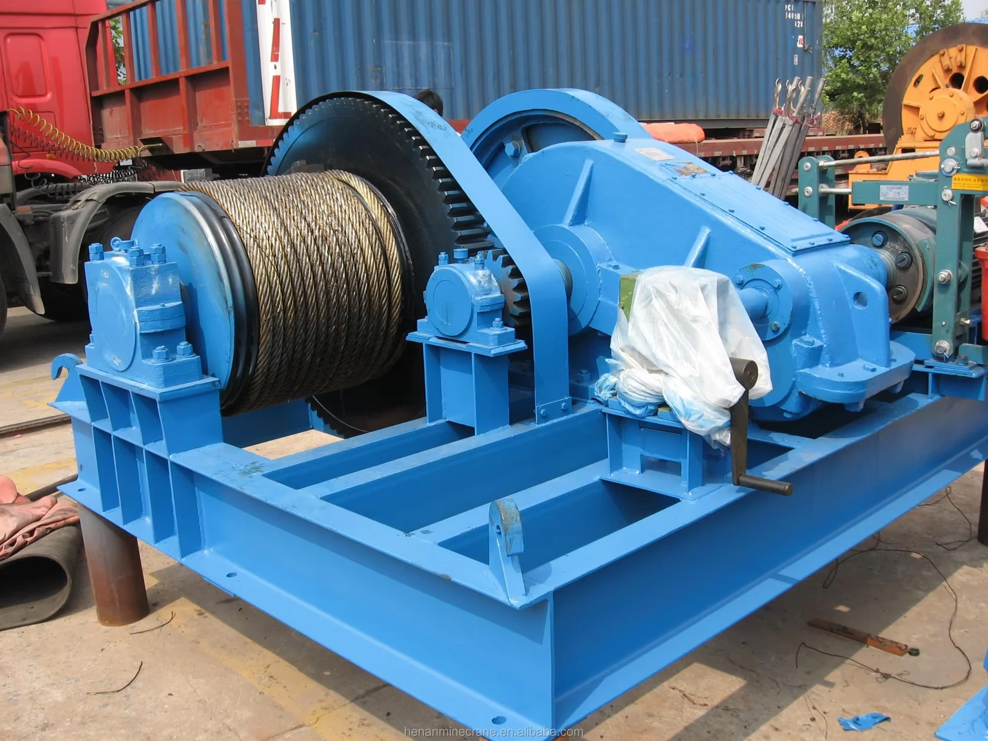
Grab buckets, magnets and hooks for your load.
Explore Lifting Attachments & Grabs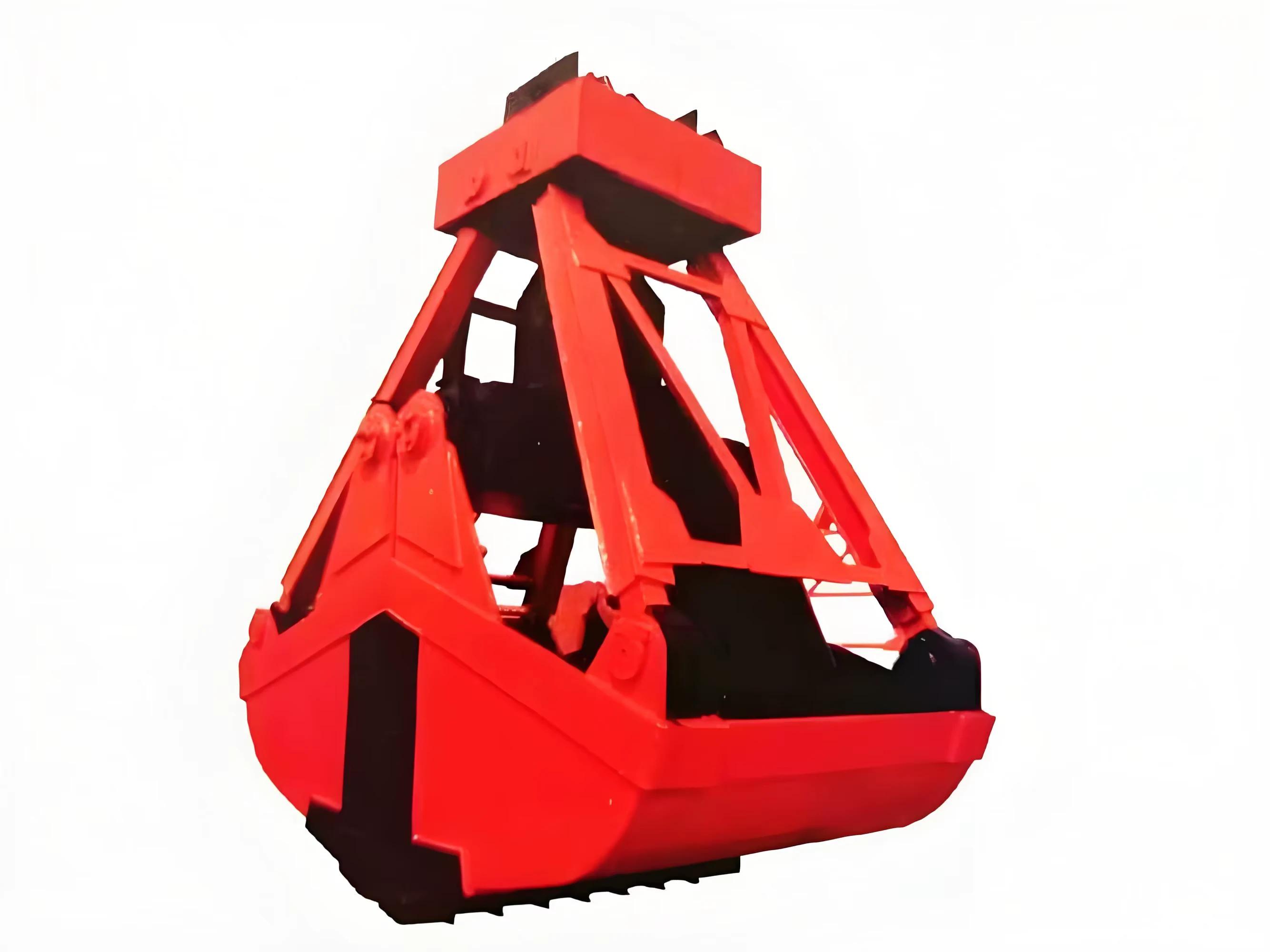
Mobile handling for containers, precast and yard loads.
Explore Rubber-Tired Gantry Cranes & Straddle Carriers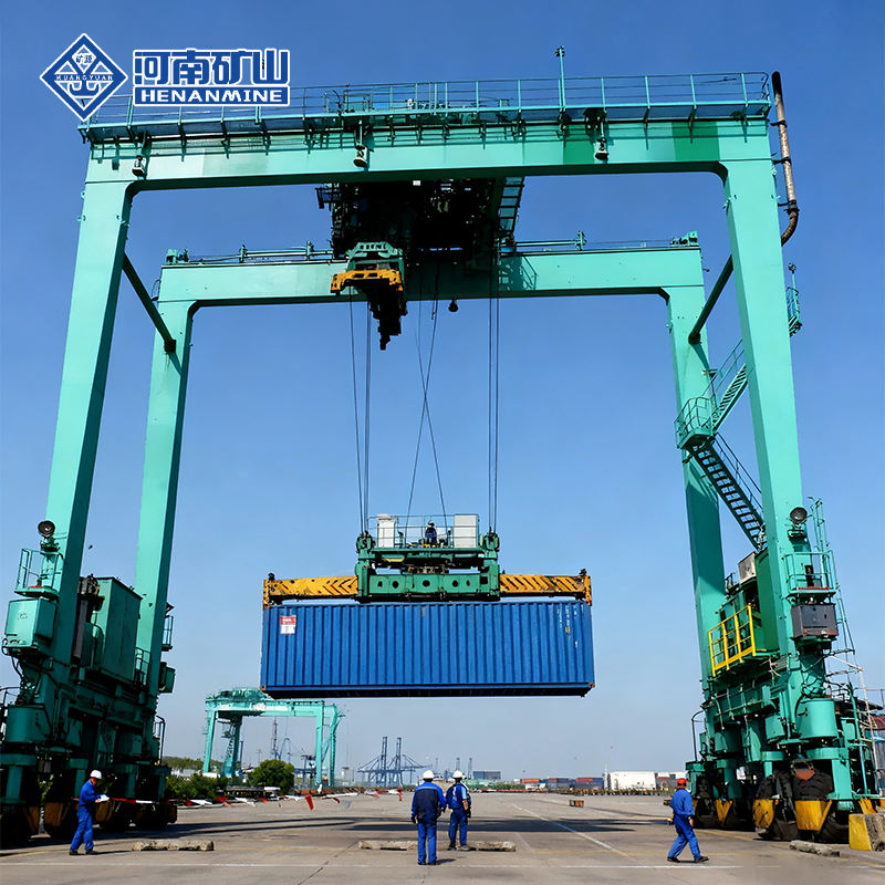
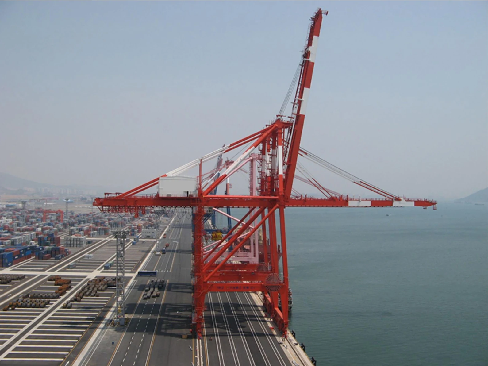
Lift and move vessels through boatyards and marinas.
Explore Marine Travel Lifts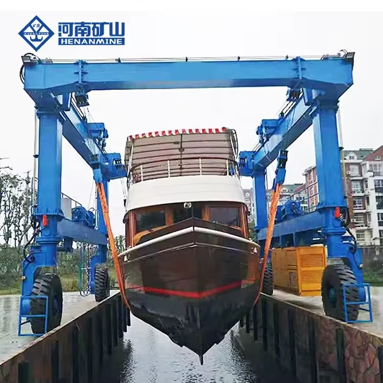
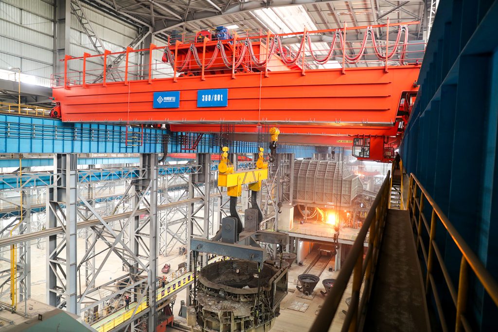
Ladle, slab, scrap and coil handling across steel production.
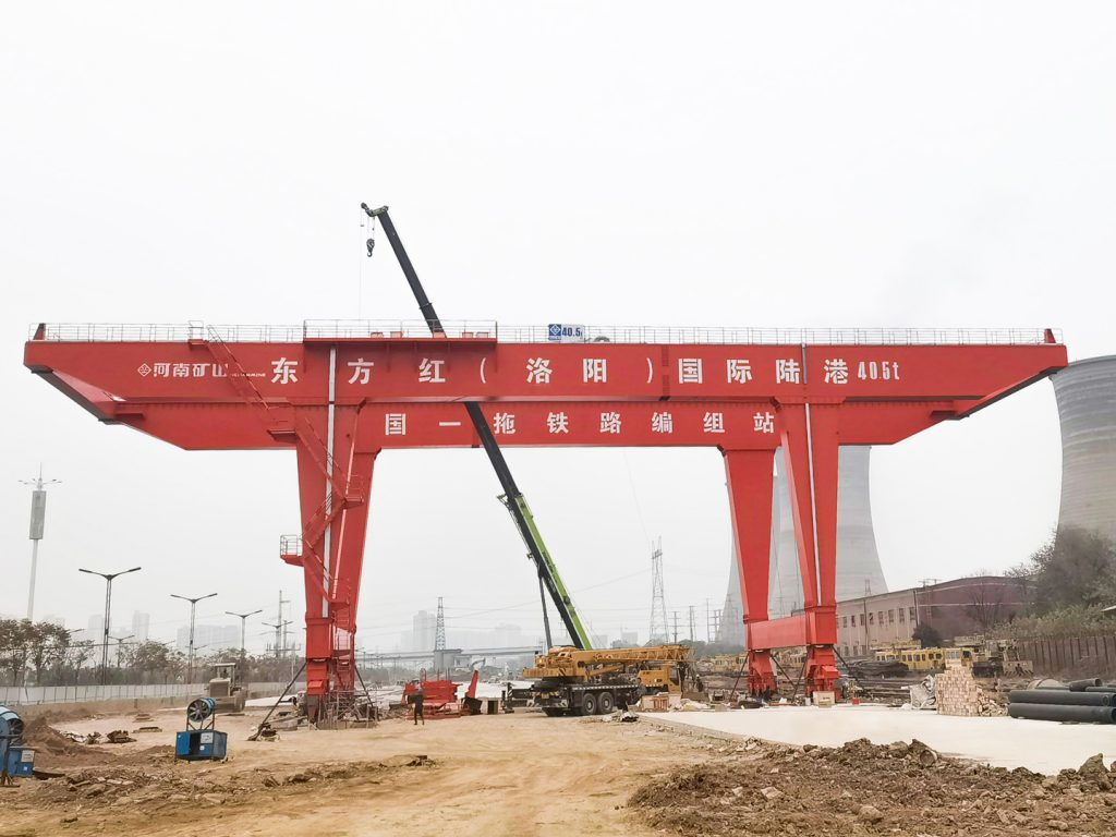
Container stacking and cargo transfers across terminals and rail.
Turbine installation, powerhouse maintenance and wind equipment assembly.
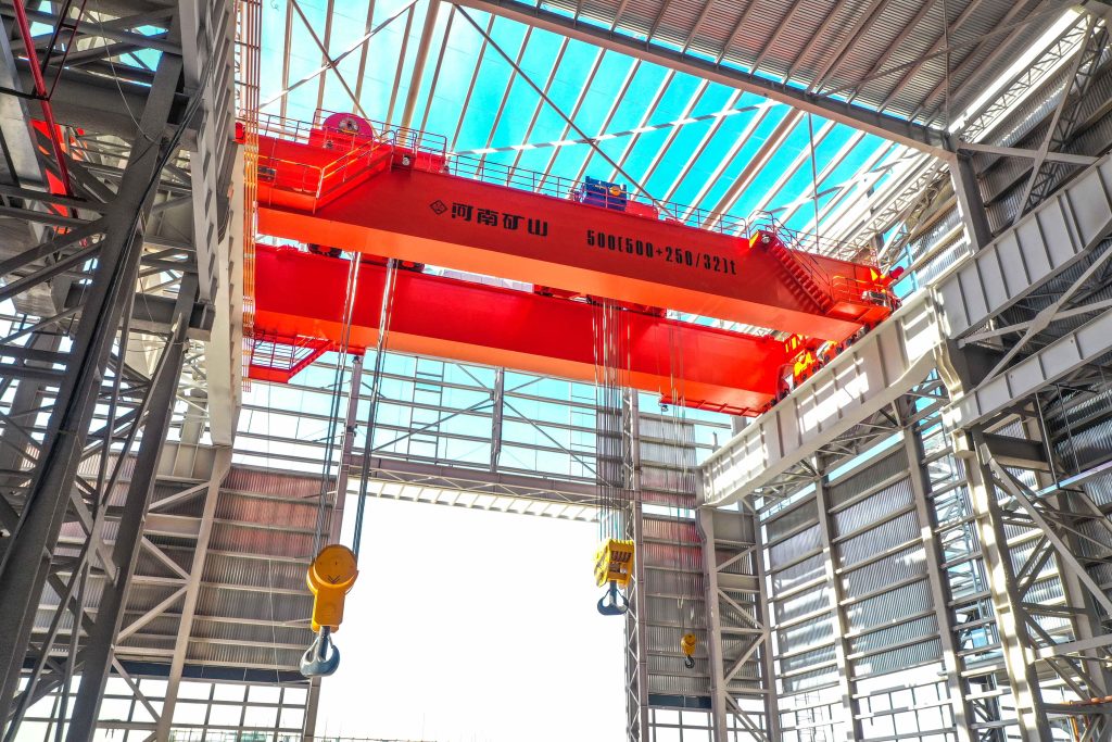
Controlled component transfer and positioning for precision assembly.
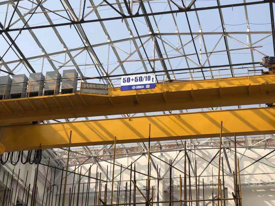
Heavy fabrication, production lifting and factory crane automation.
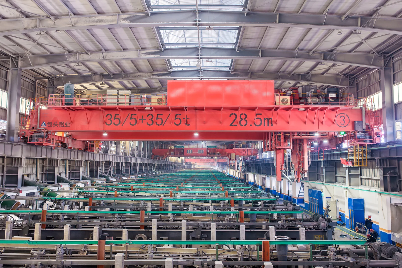
Process lifting for smelters, carbon blocks and anode materials.
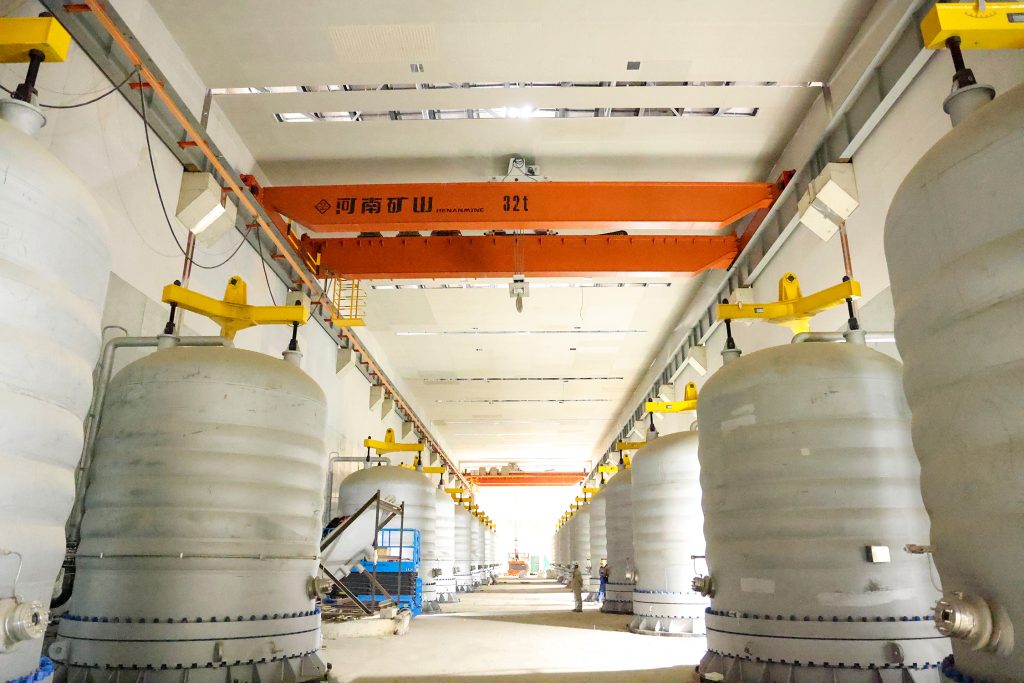
Clean lifting and classified protection for sensitive process areas.
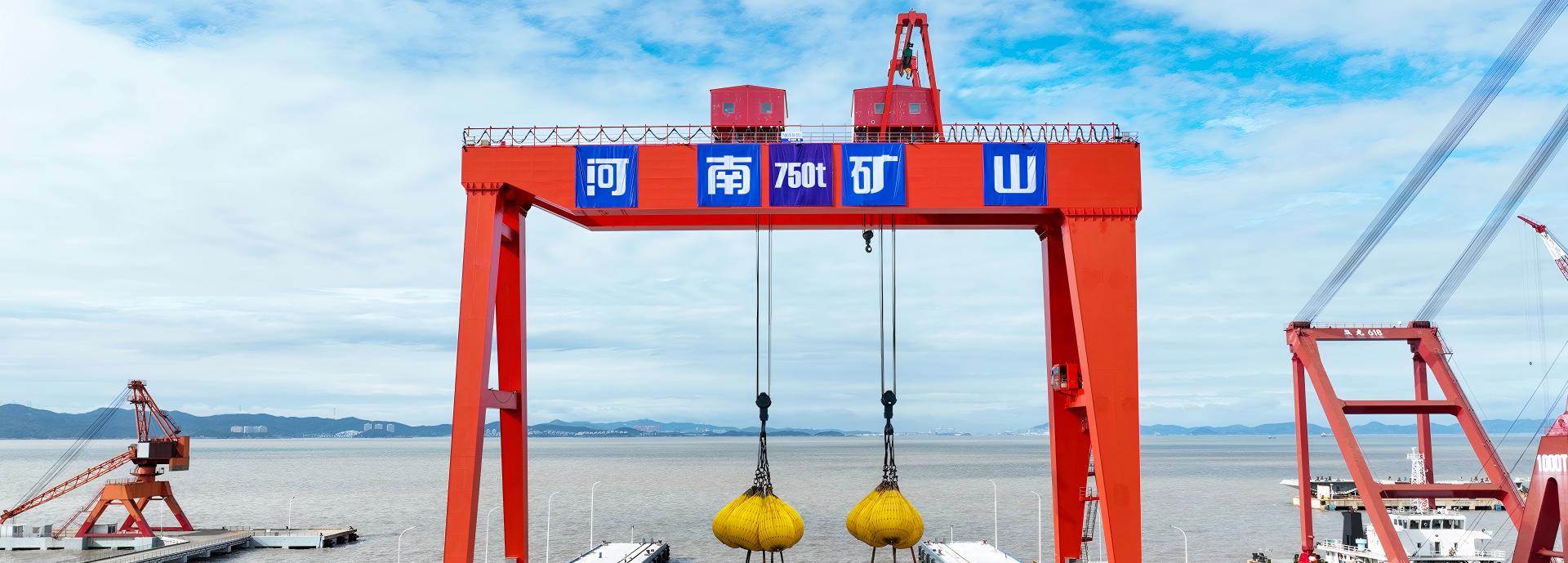
Bridge fabrication, metro construction and ship block assembly.
Automated storage and retrieval for plates, cables and bins.
Follow project dispatches, crane engineering and factory acceptance.
Dispatch, installation and equipment in service
Crane configurations and handling technology
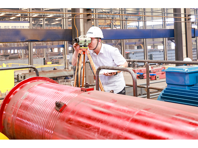
Factory inspections, acceptance and test programmes

Company developments, people and community programmes
Use this to examine elastic deflection and beam actions for one simple span with one downward point force and a full-span uniform load.
Use the form only when one simple span, one point force and a full-span uniform load reasonably represent the arrangement. Set an unused load to zero.
Use span and point position in m, force in kN, uniform load in kN/m, E in MPa and I in mm⁴.
Review maximum deflection, maximum moment, support reactions and shear. The line plot shows downward deflection along the beam, not a moment diagram.
Span 6 m; point force 20 kN at 3 m; uniform load 2 kN/m; E = 200,000 MPa; I = 200,000,000 mm⁴.
Maximum downward elastic deflection is 3.09375 mm at midspan. Maximum sagging moment is 39 kN·m; each support reaction is 16 kN.
Deflection describes movement of the ideal elastic beam; no allowable-deflection limit is assigned.
Moment and shear are unfactored internal actions. Reactions are the forces transferred to the supports in this model.
An eccentric point load can place maximum deflection away from the point load and away from midspan. The reported locations identify where the calculated maxima occur.
Entering kg as a kN point force, using Iy for bending about x, or assuming the program adds beam self-weight automatically.
RA = P × (L − a) / L + w × L / 2; RB = P × a / L + w × L / 2
M(x) = RA × x − w × x² / 2 − P × max(x − a, 0)
Elastic point-load and uniform-load deflections are superimposed; maximum deflection is located from zero slope.
No. A continuous beam has different support and bending behaviour. This tool assumes a single ideal simply supported span.
Not by itself. Strength, stability, fatigue, connections, local effects and the relevant deflection criterion must be checked separately.