Home / Gantry cranes / A-Type Gantry Cranes
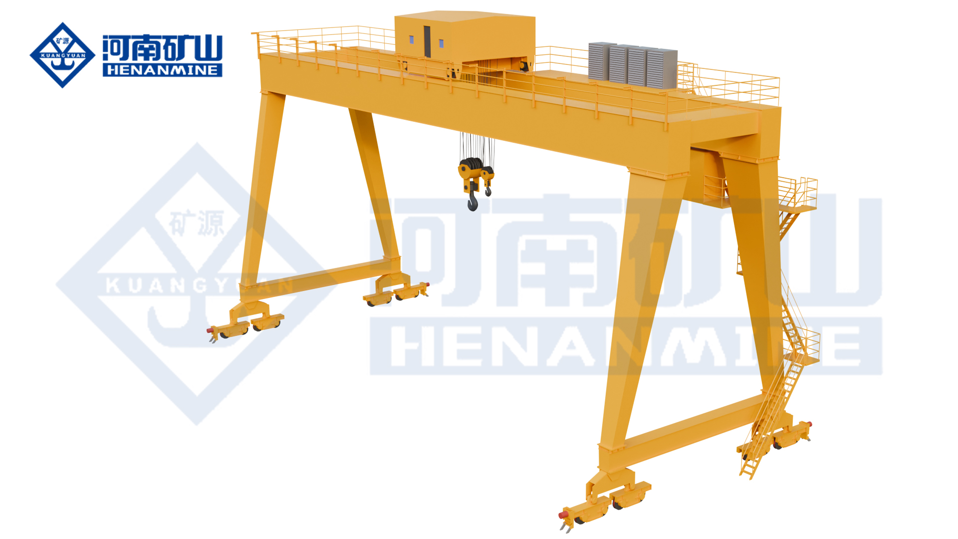
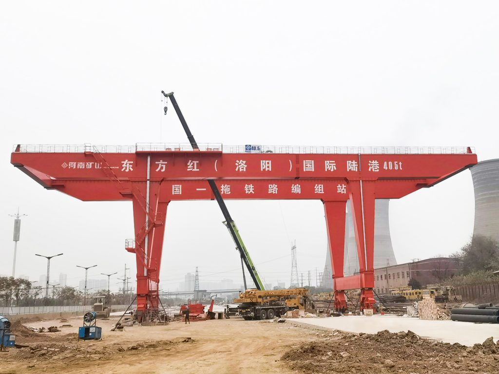
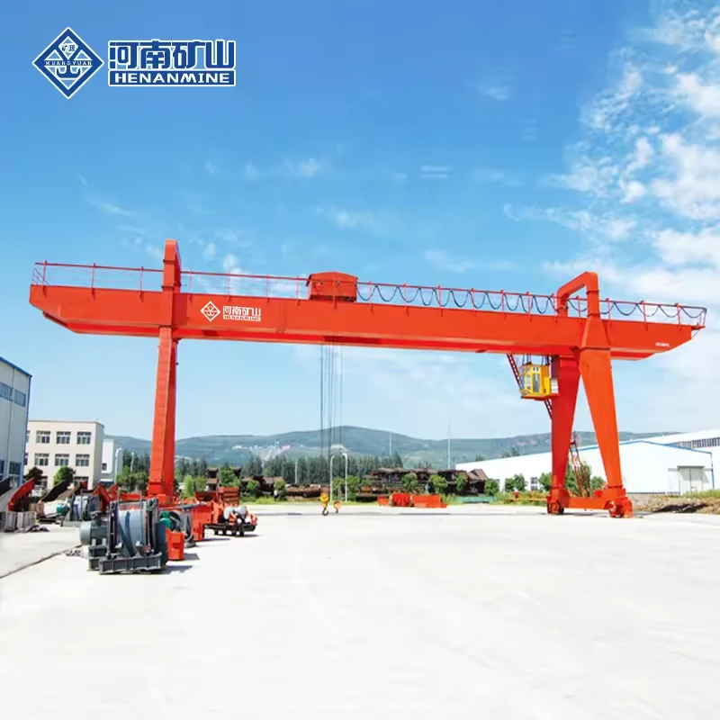
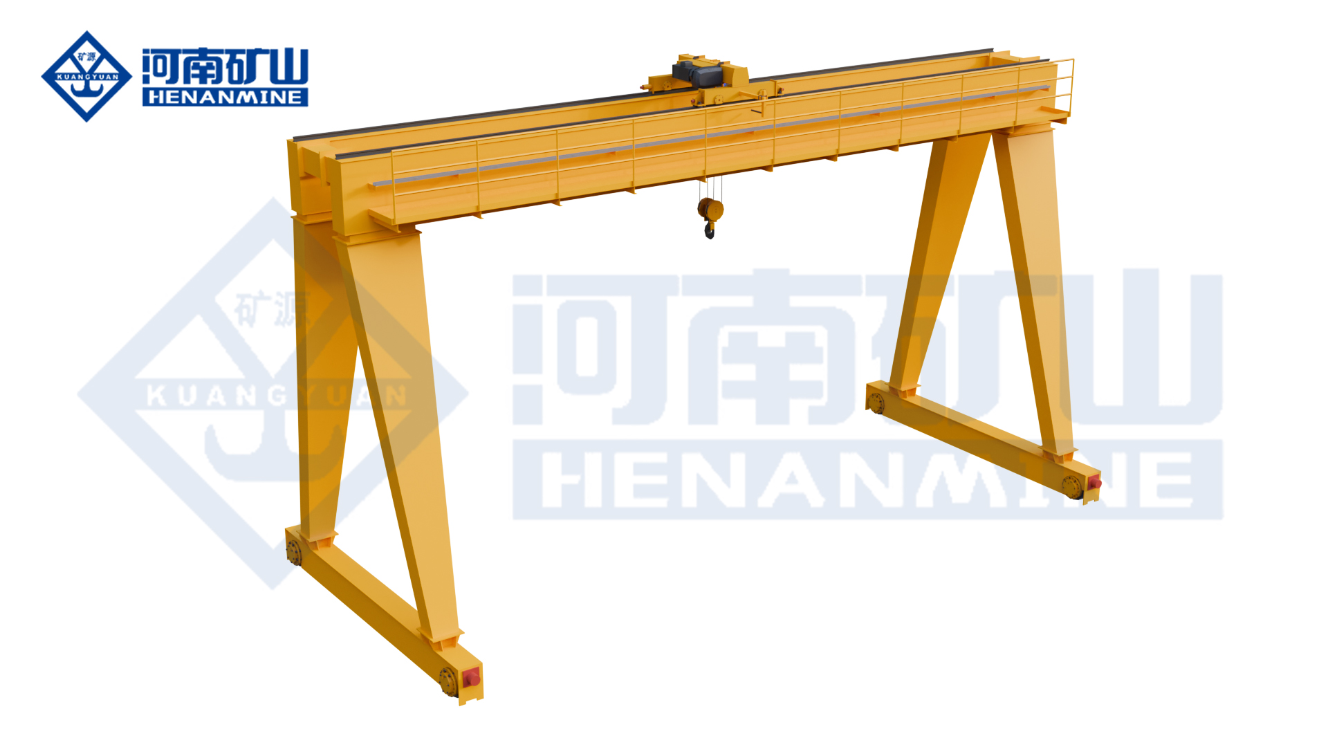
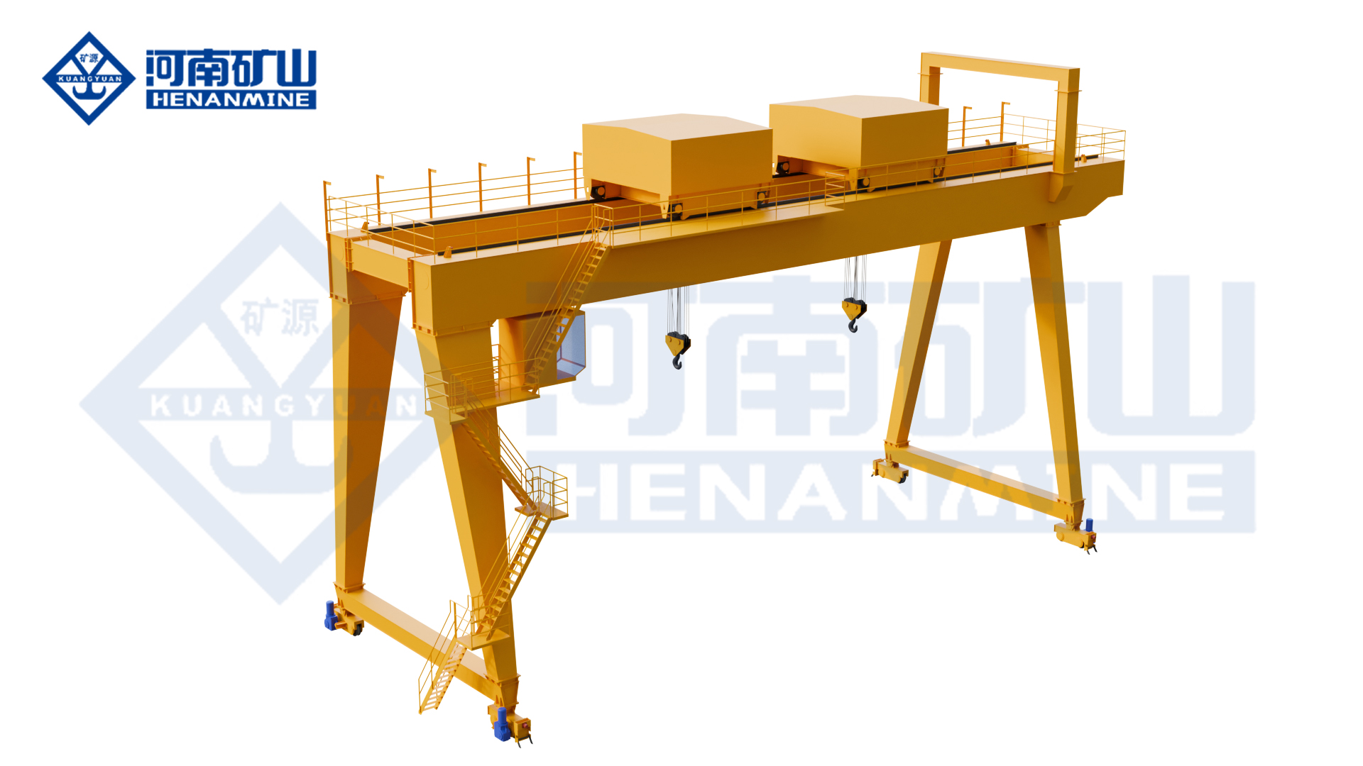
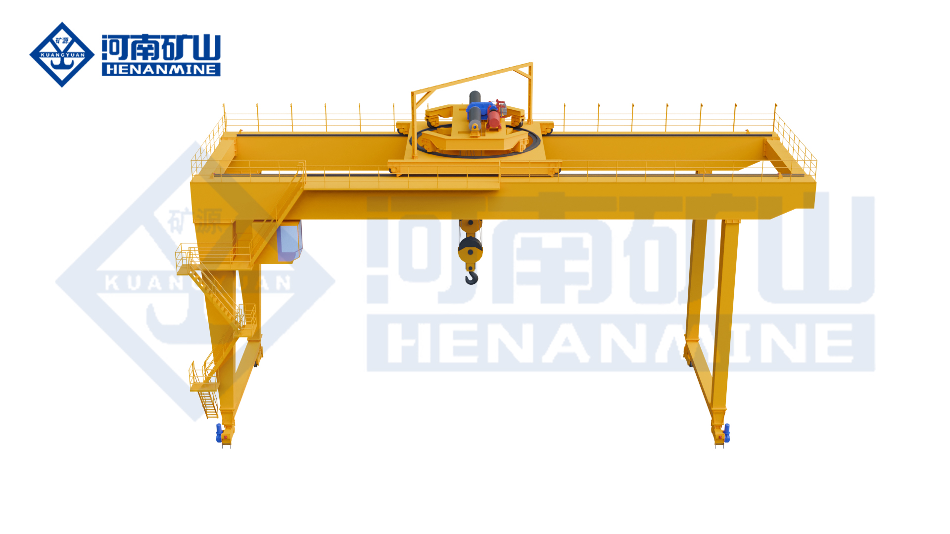
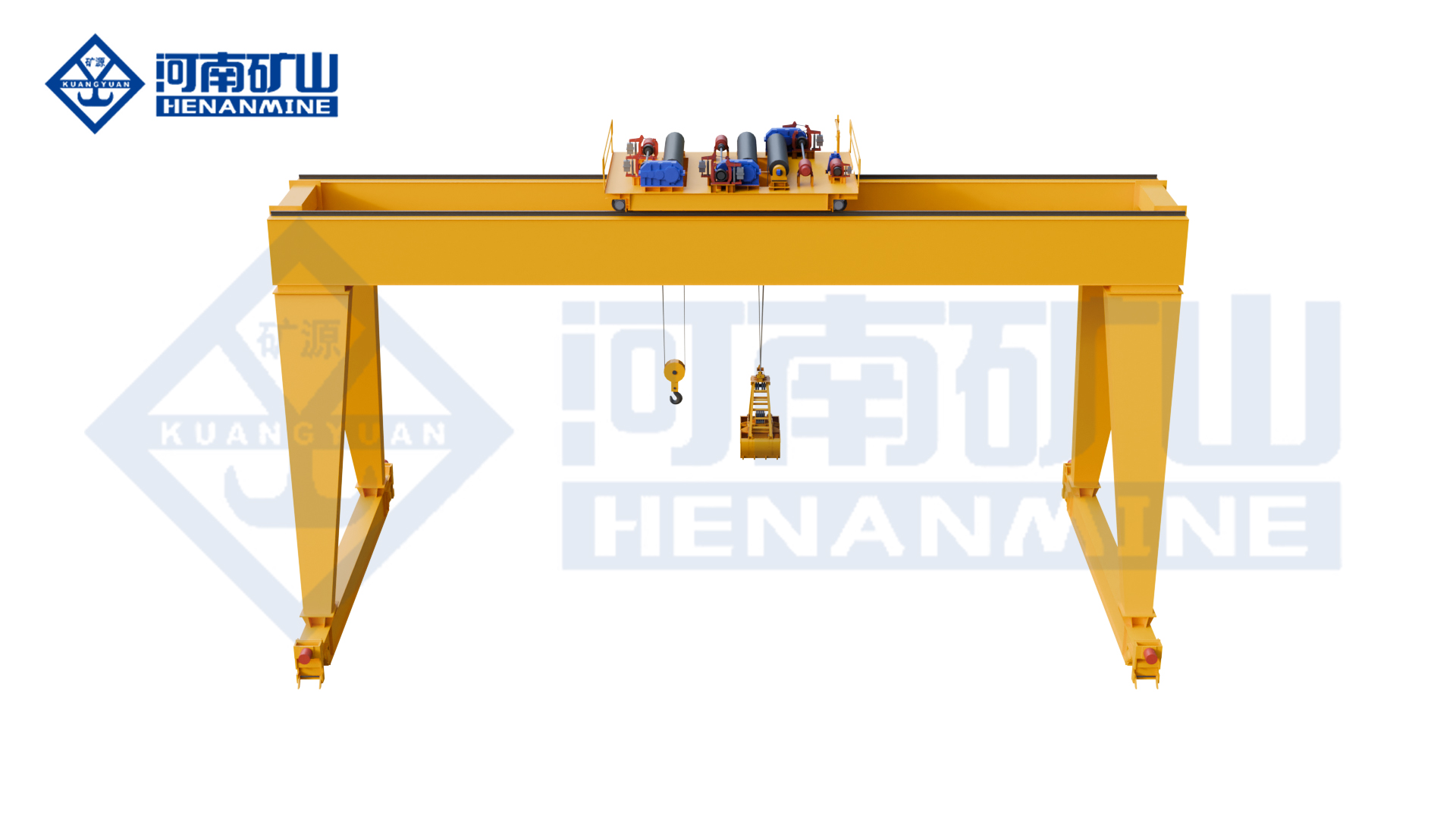
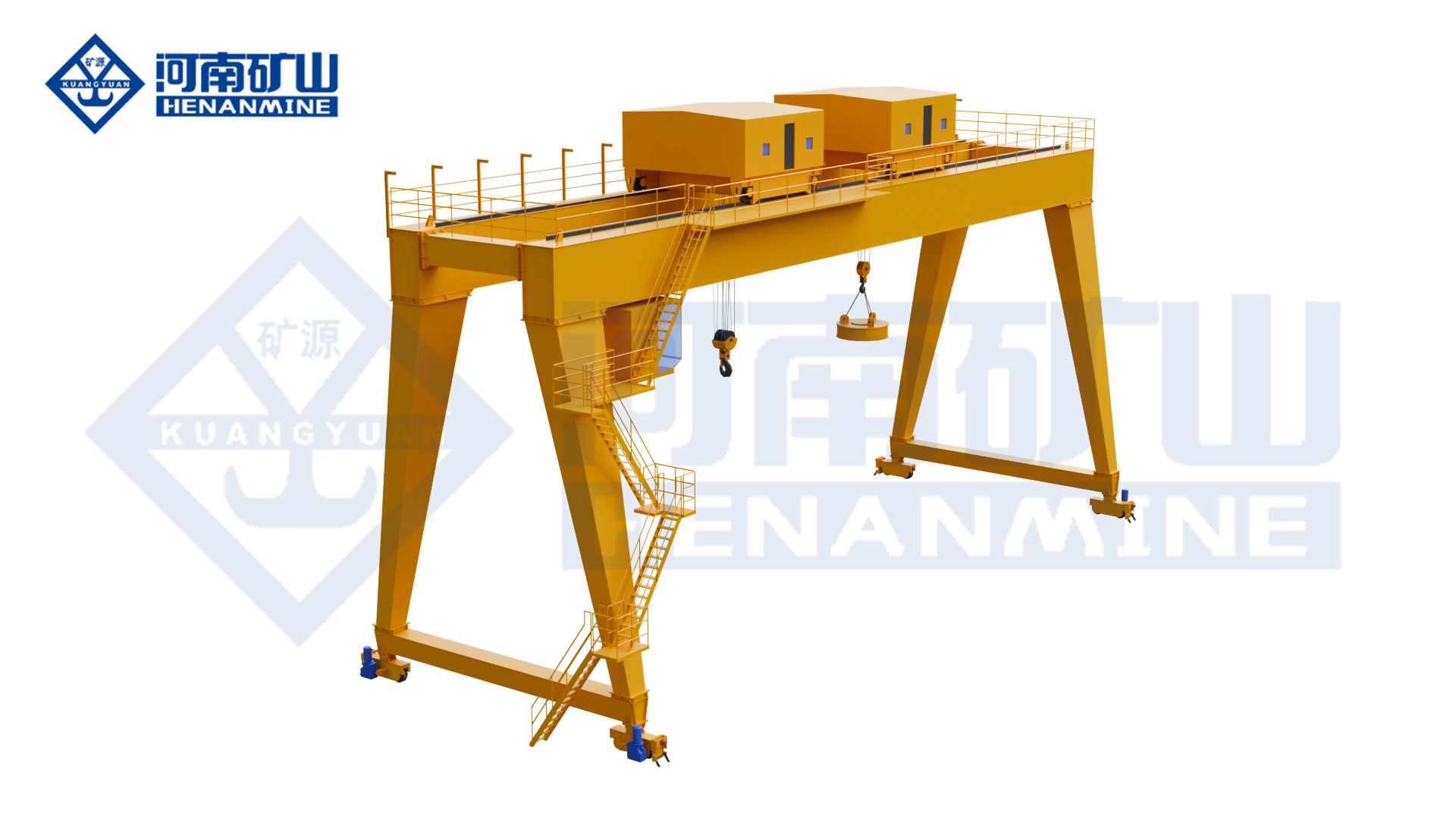
Hook and Electric-Hoist A-Frame Gantry Cranes
Hook and electric-hoist lifting for general components, repeated material transfer and loading along fixed ground runways.
MG series
Hook lifting for outdoor storage yards, workshops, component transfer and vehicle loading along ground rails.
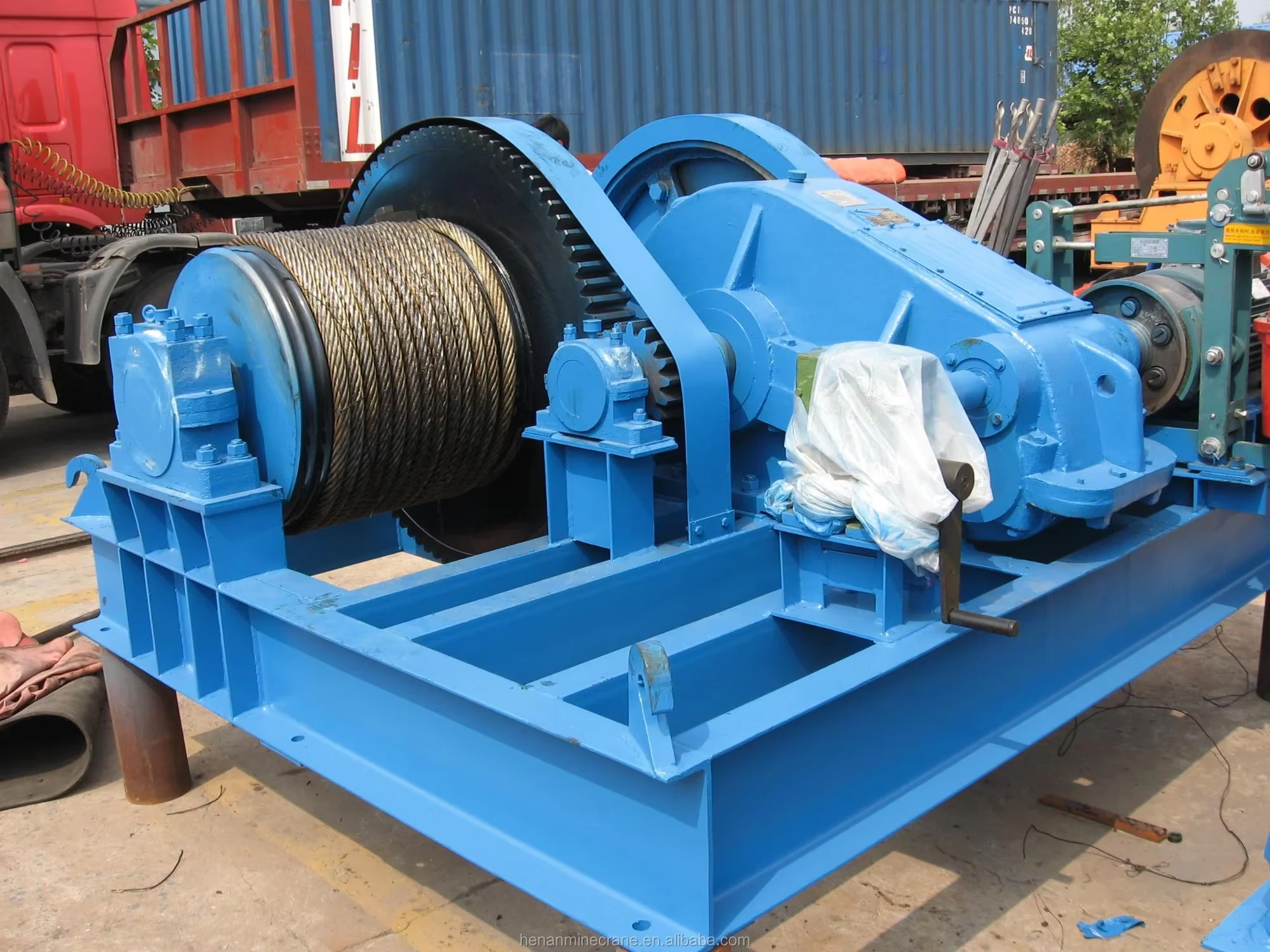
Lifting system Winch and hook
Runway Ground rails, both sides
Capacity & span Selected for the project
All specifications
Model
MG
Crane arrangement
Double-girder hook gantry
Lifting attachment
Hook
Application focus
Outdoor material handling; warehouses, factories and loading areas
Rated lifting capacity
Selected for the complete suspended load, including lifting attachments and rigging
Span
Rail-centre span selected for the working area
Lifting height
Working lifting height selected for the pickup and placement levels
Working class
Selected from load spectrum, lifts per hour and shifts
Hoisting package
Mechanism, hook block and reeving identified for the selected load and lift
Lifting speed
Loaded lifting and positioning speeds specified with the hoisting package
Trolley travel
Cross-travel speed and hook approaches selected for the transfer positions
Crane travel
Travel speed and stopping control selected for the runway
Main / auxiliary hook
Hook capacities, heights and permitted operating modes specified where an auxiliary hook is required
Hook coverage
Leg opening, end approach and any cantilever shown on the general arrangement
Operator controls
Operator position and control package selected for visibility and handling
Runway interface
Rail section, wheel loads and horizontal reactions provided for the selected crane
Electrical supply
Site voltage, frequency, phases and power-feed route specified
Outdoor exposure
Working and parked wind conditions and corrosion exposure addressed in the equipment scope
Delivery arrangement
Transport sections, assembly joints and site access agreed for the destination
Order quantity
Enquire for one complete crane or a multi-crane project
Reference scope
Separate A-frame catalogue examples; not universal MG ratings. Each set is one matched configuration. Main and auxiliary hook ratings are separate. The ordered drawing and wheel-load schedule govern.
Reference configuration
5 t · 22 m span
Rated hook load
5 t
Span
22 m
Main hook lifting height
10 m
Auxiliary hook lifting height
Not applicable
Crane working class
A5
Main hoisting speed
11.3 m/min
Auxiliary hoisting speed
Not applicable
Trolley travel speed
37.3 m/min
Crane travel speed
37.3 m/min
Total motor power
40.8 kW
Maximum wheel load
159 kN
Recommended rail
P43
Power supply
380 V, 50 Hz, 3 phase
Reference configuration
32/5 t · 22 m span
Rated hook load
32 / 5 t (main / auxiliary)
Span
22 m
Main hook lifting height
10 m
Auxiliary hook lifting height
10.73 m
Crane working class
A5
Main hoisting speed
7.5 m/min
Auxiliary hoisting speed
15.4 m/min
Trolley travel speed
37 m/min
Crane travel speed
39.4 m/min
Total motor power
99.3 kW
Maximum wheel load
258 kN
Recommended rail
Not listed
Power supply
380 V, 50 Hz, 3 phase
Reference configuration
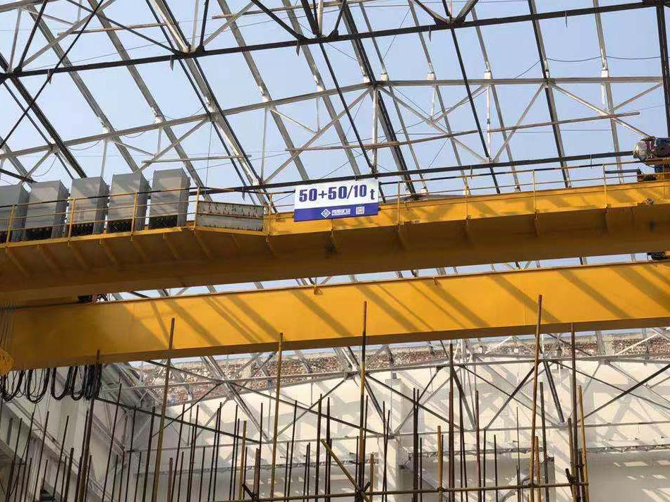
50/10 t · 30 m span
Rated hook load
50 / 10 t (main / auxiliary)
Span
30 m
Main hook lifting height
12 m
Auxiliary hook lifting height
12.918 m
Crane working class
A5
Main hoisting speed
5.9 m/min
Auxiliary hoisting speed
10.4 m/min
Trolley travel speed
36 m/min
Crane travel speed
38.5 m/min
Total motor power
126.5 kW
Maximum wheel load
409 kN
Recommended rail
Not listed
Power supply
380 V, 50 Hz, 3 phase
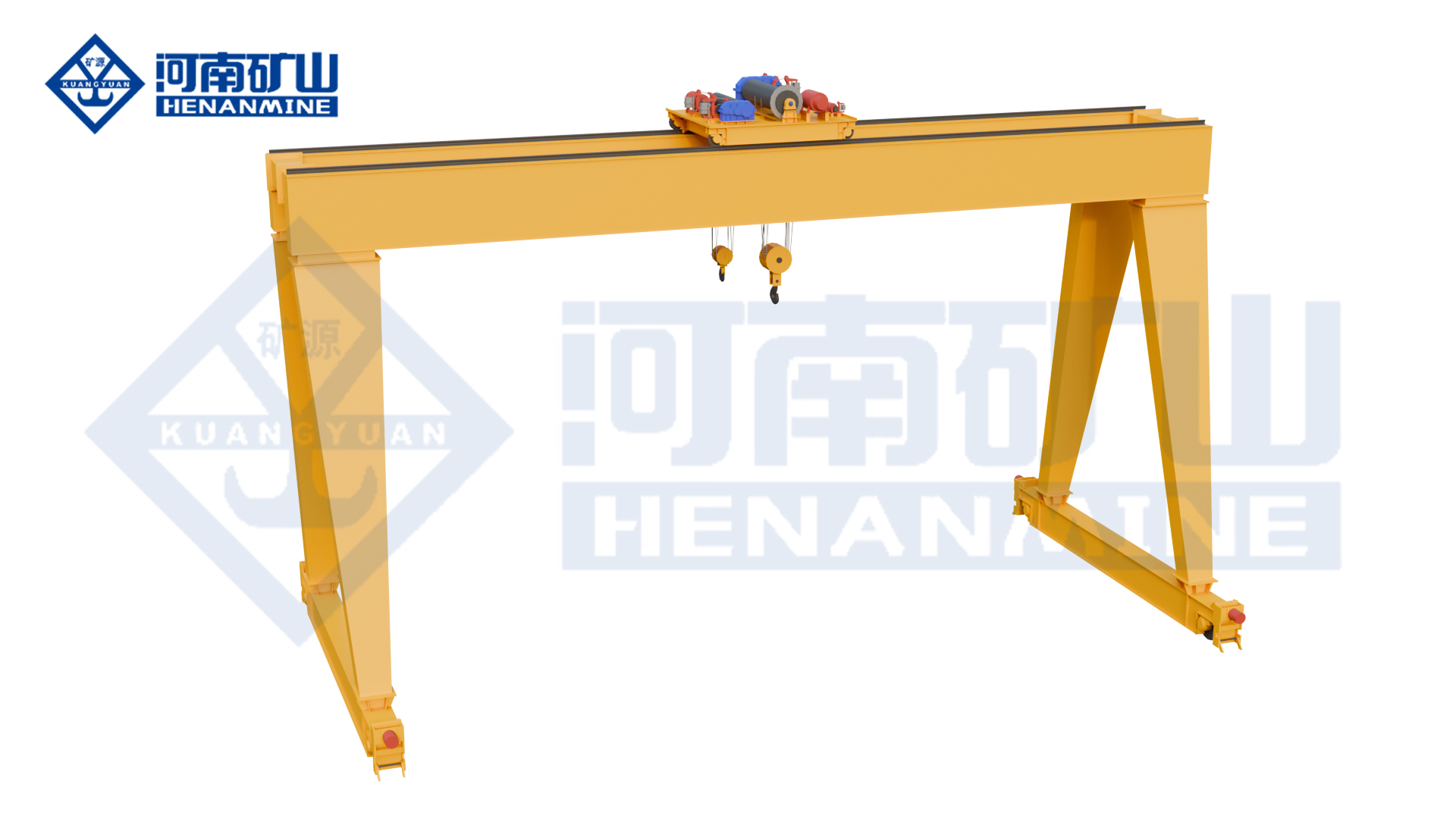
MHS series
Electric-hoist lifting for repeated loading, unloading and component transfer across a double-girder ground-rail work area.
Rated capacity 3–50 t
Span 7.5–35 m
Lifting height 4–30 m
All specifications
Model
MHS
Rated lifting capacity
3–50 t
Span
7.5–35 m
Lifting height
4–30 m
Girder arrangement
Double girder
Runway/support layout
Full gantry; ground rails on both sides
Lifting mechanism
Electric hoist
Hoist/trolley arrangement
Seated electric-hoist trolley
Lifting attachment
Hook
Working class
A-class selected for the load spectrum and operating cycle
Lifting speed
Lifting and positioning speeds matched to the selected electric hoist
Trolley travel speed
Cross-travel speed and stopping control selected for the load route
Crane travel speed
Long-travel speed selected for the runway and operating cycle
Travel drive
Motor / gearbox / brake package matched to duty and wheel reactions
Operating controls
Pendant / wireless remote / cabin options
Cantilever arrangement
With or without cantilever
Electrical supply
380 V / 50 Hz; 220–660 V / 50–60 Hz supply options
Electrical protection
IP54 option; protected equipment scope defined in the electrical schedule
Runway rail profile
Rail section matched to wheel geometry, reactions and supporting structure
Motor ratings
Lifting, trolley and crane-travel motor ratings specified in the equipment schedule
Operating pattern
Intermittent, repeated loading/unloading and material handling
Site layout
Overall height, leg clearance and hook approach shown in the crane drawing
KSMHS series
Top-running electric-hoist lifting with variable-frequency motion for controlled pickup and positioning of components and general loads.
Working class A3–A5
Motion control Variable frequency
Lifting arrangement Top-running hoist trolley
All specifications
Model
KSMHS
Rated lifting capacity
Selected for the complete suspended load, including rigging
Span
Rail-centre span selected for the working area
Lifting height
Hook travel and headroom selected for pickup / set-down levels
Girder arrangement
Double girder
Runway/support layout
Full gantry; ground rails on both sides
Lifting mechanism
Electric hoist
Hoist/trolley arrangement
Top-running electric-hoist trolley
Lifting attachment
Hook / grab / electromagnetic lifting configurations
Working class
A3–A5
Lifting speed
Lifting and positioning speeds matched to the selected electric hoist
Trolley travel speed
Cross-travel speed and stopping control selected for the load route
Crane travel speed
Long-travel speed selected for the runway and operating cycle
Travel drive / motion control
Variable-frequency lifting and travel
Operating controls
Operator control package selected for visibility and the lifting task
Cantilever arrangement
With or without cantilever
Electrical supply
Site voltage, phases, frequency and power feed matched in the electrical package
Electrical connectors
Heavy-duty electrical plug connectors: IP55
Runway rail profile
Rail section matched to wheel geometry, reactions and supporting structure
Motor ratings
Lifting, trolley and crane-travel motor ratings specified in the equipment schedule
Operating pattern
Intermittent, repeated loading/unloading and material handling
Speed adjustment ratio
1:10
Double-Trolley and Process Gantry Cranes
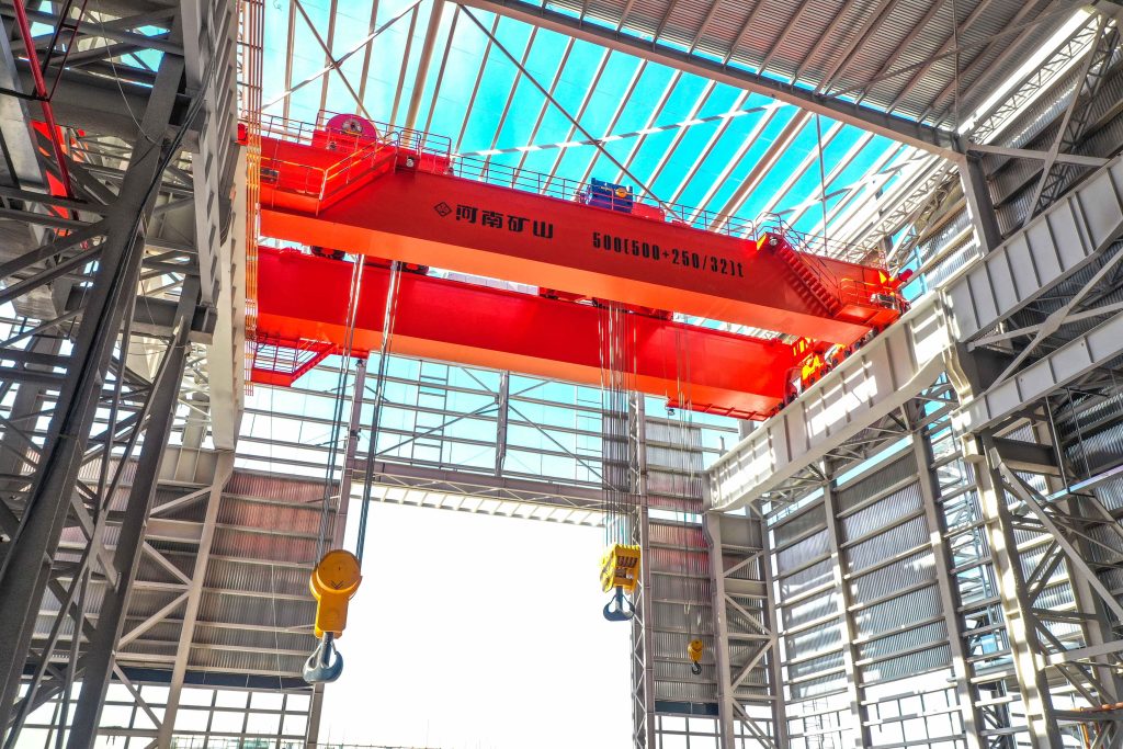
Twin-trolley, grab, magnetic and metallurgical arrangements for long components, bulk material, steel and process-specific handling.
ME series
Two-trolley lifting for long components and handling sequences requiring separated, independently usable or coordinated lifting positions.
Lifting trolleys Two
Operating modes Independent or joint
Working-class options A3–A8, selected to duty
All specifications
Model
ME
Trolley arrangement
Two travelling lifting trolleys
Operating modes
Trolleys can operate independently or jointly
Working-class range
A3–A8; select the class for the operating cycle
Travel drives
Three-in-one direct-connected crane and trolley travel drives
Trolley feedback
Encoder-based double-trolley control
Drive control
Variable-frequency drive control with CI-card functionality
Cantilever arrangement
One side, both sides or no cantilever, according to the selected layout
Working motions
Vertical lifting, cross travel and crane long travel
Rated lifting capacity
Specify the rating of each trolley and the permitted combined lifting load
Span
Rail-centre span selected for the working area
Lifting height
Working lifting height selected for the pickup and placement levels
Lifting-point spacing
Usable trolley separation selected for the load geometry
Coordinated control
Load sharing, positioning and permitted joint motions defined for the handling sequence
Projection warning light
Hoisting-area projection light available by configuration
Lifting attachment
Hook or other specified attachment matched to the handling task
Lifting and travel speeds
Working and positioning speeds specified for each motion
Operator controls
Operator position and independent / joint control functions specified
Electrical supply
Site voltage, frequency, phases and power-feed route specified
Runway reactions
Wheel-load and horizontal-reaction schedule supplied for the selected arrangement
MZ series
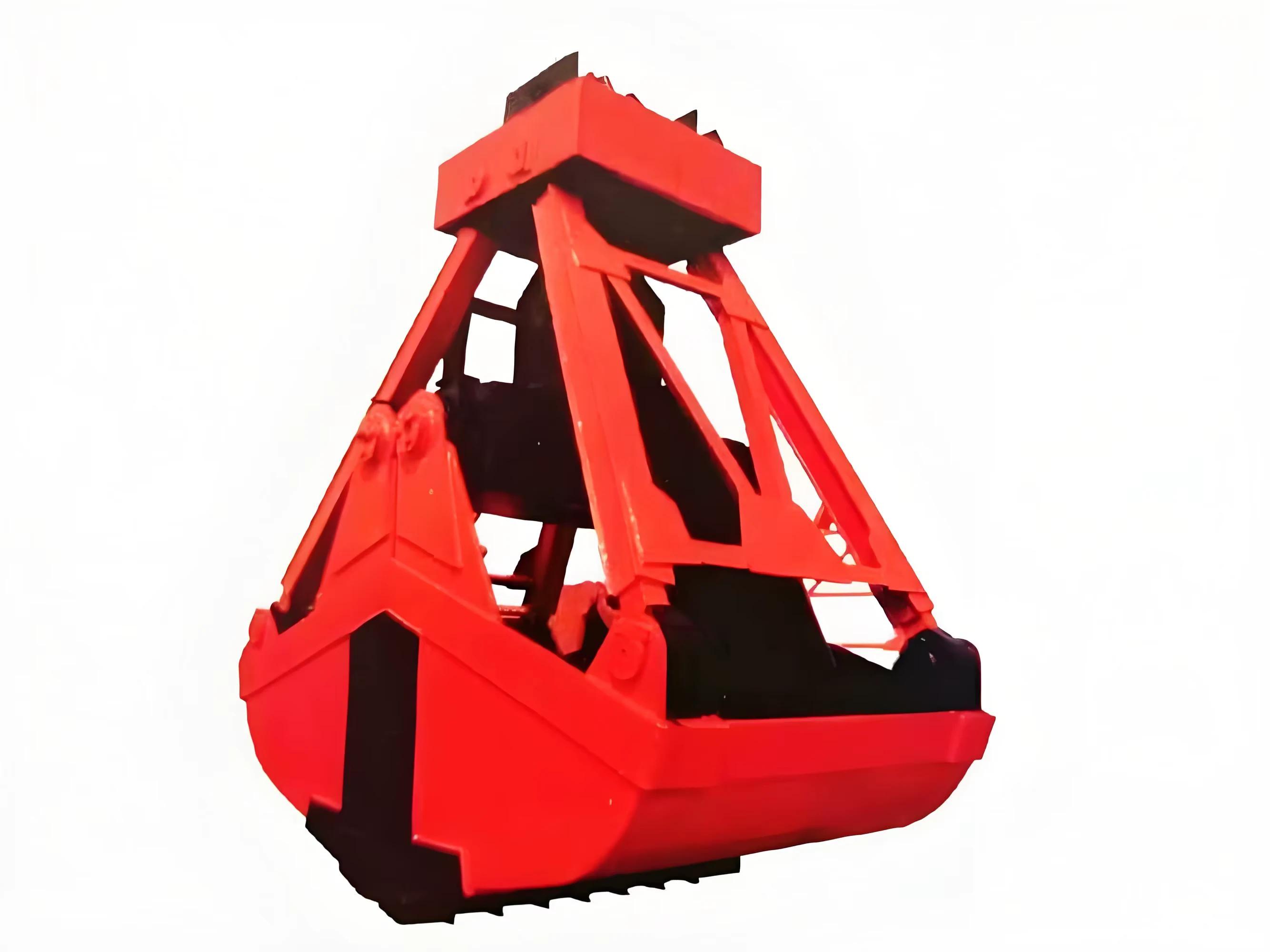
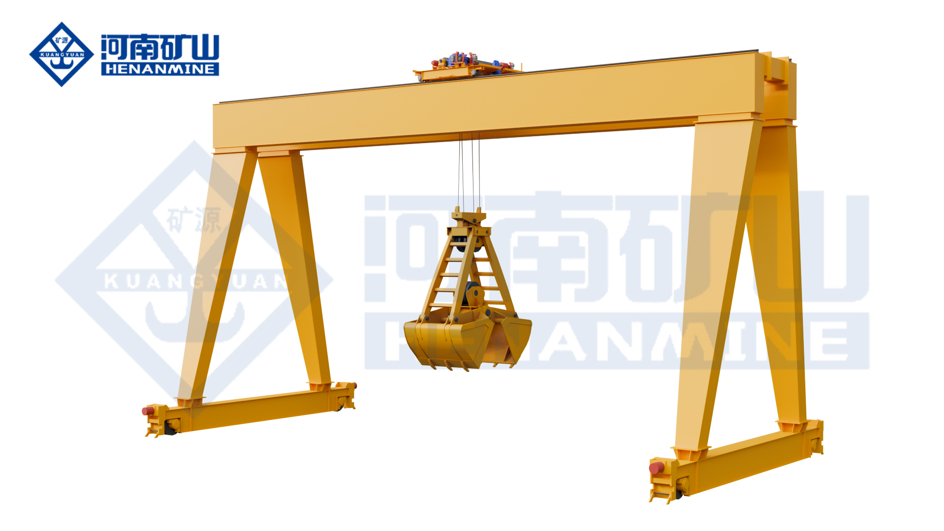
Grab handling for repeated loading, transfer and discharge of loose bulk material in a dedicated work area.
Attachment Dedicated grab
Reference load 20 t suspended load
Reference span options 18–35 m
All specifications
Model
MZ
Rated-load reference
20 t; check the complete suspended load with the selected grab
Crane structure
Double-girder gantry frame
Primary attachment
Grab
Handling task
Dedicated bulk-material loading and unloading
Runway arrangement
Legs on both sides; ground-level rail travel
Working motions
Grab lifting, trolley cross travel and crane long travel
Structural design
Main and end-girder stress distribution optimised by finite-element analysis
Rated suspended load
Grab self-weight plus material load and connecting equipment
Span options, reference package
18–35 m; select the matched load/span arrangement
Maximum lift, reference package
10 m; confirm the grab working levels
Grab volume
Selected from material density and the required load per cycle
Material properties
Specify density, particle size and flow characteristics
Bulk density, reference grab
< 1.5 t/m³ for the stated grab package
Grab actuation
Hydraulic or mechanical opening / closing selected with the grab
Grab cycle
Opening / closing speed and full handling cycle confirmed for the material and grab
Duty options, reference package
A6–A8; selected for the required load spectrum
Automation control
Manual and automated operating functions specified in the control package
Authorised access
Fingerprint-based operator access available by configuration
Camera system
Multiple camera views and operator display available by configuration
Lifting and travel speeds
Motion speeds selected for pickup, transfer and controlled discharge
Electrical supply
Crane and grab power / control interfaces specified for the site
MC series
Electromagnetic lifting for transfer and stacking of suitable ferrous scrap, billets and other steel loads.
Lifting system Electromagnetic
Materials Suitable ferrous loads
Motion control Variable frequency
All specifications
Model
MC
Crane structure
Double-girder electromagnetic gantry
Lifting attachment
Integrated electromagnetic lifting system
Material focus
Ferromagnetic material such as suitable scrap and steel billets
Motion control
Variable-frequency control throughout the crane
Structural arrangement
Modular crane design
Wheels
Forged wheels
Transmission coupling
Crowned gear coupling
Rope drum
Rolled steel-plate drum
Protection functions
Overload protection, travel limits, buffers and wind protection
Cantilever arrangement
One side, both sides or no cantilever, according to the selected layout
Rated suspended load
Material plus magnet, suspension and connecting equipment
Span
Rail-centre span selected for the working area
Lifting height
Working lifting height selected for the pickup and placement levels
Magnet selection
Magnet arrangement selected for steel form, load condition and temperature
Magnet electrical package
Power supply, holding / release functions and any backup requirements defined in the offer
Working class
Selected for the magnet handling cycle, load spectrum and shifts
Motion speeds
Lifting, trolley and crane-travel speeds specified for the work route
Operator controls
Operator position, visibility and magnet control functions selected together
Runway and wind interface
Wheel reactions and specified wind-restraint provisions coordinated with the site
MN series
Grab-and-hook handling for work areas receiving loose bulk material alongside components and general cargo.
Handling modes Grab and hook
Changeover Quick-connection arrangement
Duty basis Defined for each mode
All specifications
Model
MN
Handling modes
Grab for bulk material; hook for general cargo
Changeover system
Dedicated quick-connection arrangement for grab / hook exchange
Grab rope system
Coordinated opening / closing ropes and supporting ropes for a rope-operated grab
Hook mode
Conventional hook-lifting operation
Motion control
Variable-frequency control
Wheel manufacture
Combined forging and rolling process
Transmission coupling
Crowned gear coupling
Maintenance arrangement
Modular design with replaceable core components
Grab-mode suspended load
Grab self-weight plus carried material and connecting equipment
Hook-mode capacity
Complete hook-lifted load including slings and attachments
Span
Rail-centre span selected for the working area
Lifting height
Pickup level, discharge height and attachment dimensions selected together
Grab volume and material
Selected from material density, particle size and required load per cycle
Grab actuation
Hydraulic or mechanical opening / closing selected with the attachment package
Grab cycle
Opening / closing speed and full handling cycle confirmed for the selected configuration
Working duty
Load spectrum and cycle defined separately for grab and hook modes
Changeover procedure
Connection, parking and attachment-handling provisions agreed for the work area
Operator controls
Mode selection and required rope / attachment control functions specified
Electrical supply
Crane and any separate attachment power / control interfaces specified
MEN series
Double-trolley magnetic and hook handling for steel material and processes requiring different lifting arrangements.
Trolley arrangement Double trolley
Handling modes Magnet and hook
Working-class options A3–A8, selected to duty
All specifications
Model
MEN
Trolley arrangement
Double trolley
Handling modes
Electromagnetic and hook handling
Working-class range
A3–A8; select the class for the operating cycle
Control platform
PLC module integrated with the control station
Operator interface
HMI touch-screen interface
Master controller
WLK master controller
Controller functions
Defined operating steps, zero-return and locking functions
Magnet actuation
Pickup and release through electrical current switching
Structural design
Main-girder, leg and end-girder stress distribution optimised by finite-element analysis
Cantilever arrangement
One side, both sides or no cantilever, according to the selected layout
Rated lifting capacity
Specify complete suspended load for each hook and electromagnetic handling mode
Span
Rail-centre span selected for the working area
Lifting height
Hook and magnet working heights selected for pickup and stacking levels
Trolley coordination
Permitted independent and coordinated functions defined for the process
Magnet package
Magnet type, suspension, power circuit and required holding / release functions specified
Steel material
Specify material form, dimensions and relevant operating temperature
Duty and handling rate
Selected for the actual pickup, travel, release and return cycle
Motion speeds
Lifting and travel speeds selected for controlled material placement
Site electrical supply
Voltage, frequency, phases and crane / magnet power-feed interfaces specified
MGY series
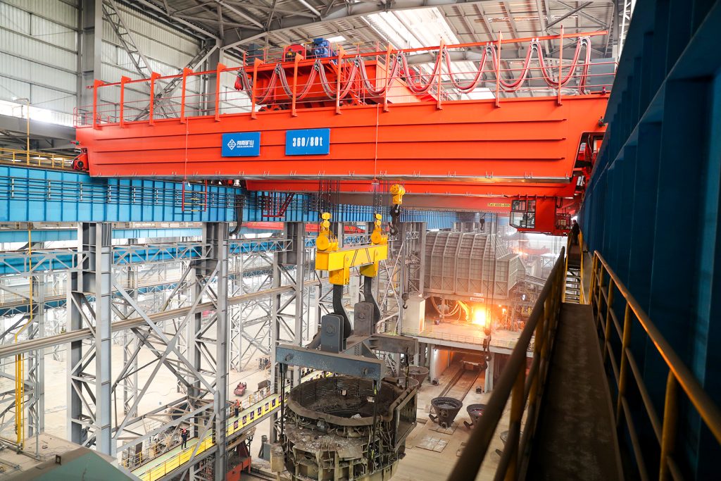
Metallurgical lifting for specified steel-ladle handling and slag-pot maintenance, with a vessel-matched attachment and heat-protection arrangement.
Application Ladle or slag-pot handling
Protection Heat-protection arrangement
Controls PLC and HMI
All specifications
Model
MGY
Crane structure
Metallurgical double-girder gantry
Lifting attachment
Gantry-hook attachment for the selected vessel
Application focus
Steel-ladle lifting or slag-pot maintenance
Thermal protection
Heat protection for key main-girder and leg structures
Thermal exposure
Arrangement intended for radiant-heat exposure in metallurgical work
Control platform
PLC module with HMI touch screen
Master controller
WLK controller with defined steps, zero-return and locking functions
Lifting control
Stator-voltage regulation for lifting speed control
Travel control
Variable-frequency travel-speed control
Structural design
Key load-bearing members optimised by finite-element analysis
Rated lifting capacity
Vessel, contents, lifting attachment and connecting equipment assessed together
Span
Rail-centre span selected for the working area
Lifting height
Working hook levels selected for vessel pickup, transfer and maintenance
Vessel interface
Gantry-hook geometry and engagement matched to the vessel lifting points
Process and duty
Load spectrum, handling sequence, shifts and required operating modes specified
Heat conditions
Vessel temperatures and radiant-heat exposure stated for the selected equipment
Lifting and travel speeds
Loaded, positioning and travel speeds specified for the process
Electrical package
Site supply, protection and cable routing selected for the environment
Runway reactions
Rail interface, wheel loads and relevant horizontal reactions provided for the selected crane
Construction and Mobile A-Frame Gantry Cranes
Construction and mobile arrangements for precast components, site materials and long fabricated loads moving between work positions.
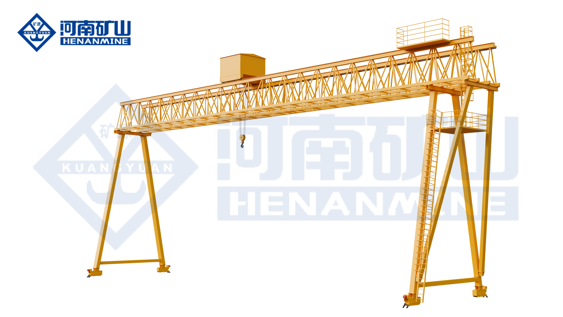
MGG series
Single-trolley winch lifting on a twin-truss gantry for precast beams, construction materials and specified engineering tasks.
Bridge Twin truss girders
Lifting arrangement Single trolley and winch
Application Bridge and highway work
All specifications
Model
MGG
Main-girder structure
Twin truss main girders
Leg structure
Tubular steel legs
Trolley arrangement
Single trolley
Hoisting mechanism
Single winch
Application focus
Bridge and highway construction work
Handling tasks
Precast-beam lifting, material transfer and specified piling-spoil operations
Rated lifting capacity
Selected for the complete suspended load, including lifting attachments and rigging
Span
Rail-centre span selected for the construction work area
Lifting height
Working hook travel selected for the construction lifting sequence
Working class
Selected for the load spectrum, lifts per hour and shifts
Lifting attachment
Hook, lifting beam or other attachment specified for the actual load
Hoisting speed
Loaded lifting and positioning speeds selected with the winch package
Trolley travel
Cross-travel speed and usable hook approaches specified for the load route
Crane travel
Long-travel speed and stopping control selected for the runway
Site clearances
Leg opening, load envelope and vehicle access shown in the arrangement
Transport and assembly
Transport sections, site assembly and installation access agreed
Operator controls
Operator position and control package selected for visibility
Electrical supply
Voltage, phases, frequency and power-feed route specified
Runway and exposure
Wheel reactions, rail interfaces and relevant wind provisions coordinated with the site
Mobile A-frame configuration
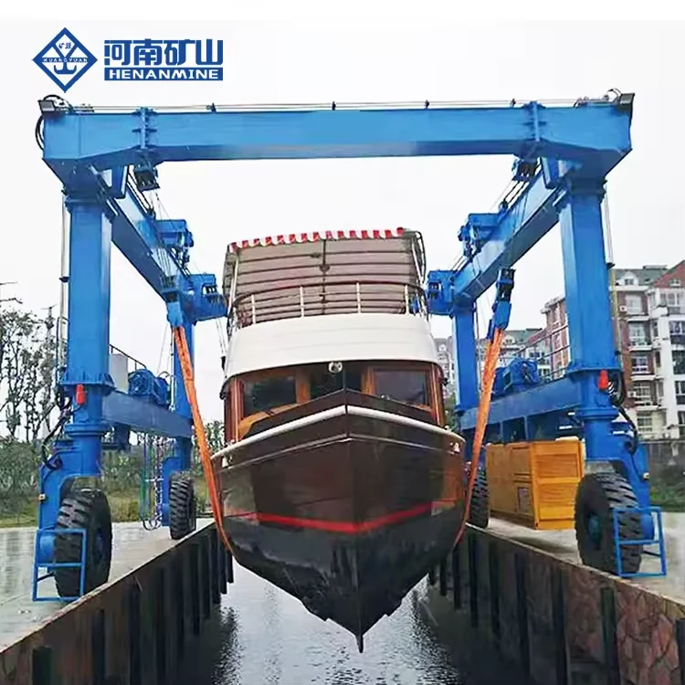
Rubber-tired lifting and transport of long fabricated components between work positions along a defined site route.
Travel system Rubber tired
Handling task Long fabricated components
Site interface Route, pavement and turning
All specifications
Product type
A-frame rubber-tired gantry crane
Travel system
Rubber-tired mobile travel
Handling purpose
Lifting and transporting long fabricated components
Rated lifting capacity
Selected for the complete suspended load
Clear working width
Selected around the workpiece, lifting connections and travel route
Useful lifting height
Specified for pickup, transport and set-down levels
Lifting-point arrangement
Selected for workpiece support, spacing and permitted operating modes
Steering and turning
Selected for the loaded route and operating clearances
Ground interface
Tire/axle reactions and pavement capacity checked for the selected arrangement
Supply scope
Crane, power package, controls, documents and site support defined in the offer
Capacity, span, lift, duty and speeds are selected together. Include attachments in the suspended load; main and auxiliary hook ratings are separate.
Budget planning
How much does an A-type gantry crane cost?
Compare prices for the same capacity, span, lifting height, duty and delivery scope.
Published A-type double-girder reference configurations
Crane configuration
Reference price (USD)
20/5 t · 24 m span · 9 m lift · 3 / 3 m cantilevers (left/right) · A5
USD 80,029
20/5 t · 28 m span · 10 m lift · 10 / 10 m cantilevers (left/right) · A5
USD 104,500
Third-party examples published August 2025 and checked October 2026. These are not current Henan Mine Crane offers or delivered costs; trade terms and full supply scope are undisclosed.
Request an itemized offer covering the crane, rails, power feed, freight and site services. A 20/5 t rating identifies separate main and auxiliary hooks.
Get a quote for your configuration
Project experience
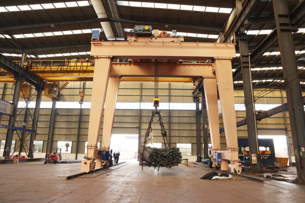
100 t Gantry Crane for a Nuclear Project
A 100 t double-girder gantry completed factory acceptance for a nuclear project, including heavy-load movement and positioning tests. The project’s factory-test image shows the crane carrying a suspended load, documenting this stage of the equipment acceptance process.
View project
100 t nuclear-project gantry during factory testing.
A-type gantry crane buying questions
Is an A-type crane the same as a double-girder crane?
A-type describes the supporting legs; double girder describes the bridge. The lifting mechanism and trolley arrangement are separate features.
Can two trolleys lift one long load?
Yes, within the selected operating mode. Each trolley’s rating, lifting-point spacing and permitted shared load are specified together; the two ratings are not automatically additive.
Can I enquire while dimensions are unknown?
Yes. Start with the load, approximate span or clear width, useful hook height and destination. Leave unknown dimensions blank; an optional sketch helps explain the material route.
Compare the range
A-type gantry crane specification comparison
Compare arrangement, load, span, lift and duty. Select a product name to view its details.
Swipe across the table to compare specifications.
Model options and reference figures are selected as a complete crane configuration. The technical offer confirms the load, dimensions, duty, operating modes and supplied equipment.
Get an A-type gantry crane quote
Send the load, span or clear width, useful lifting height and destination. Add a sketch if available.
Unknown dimensions can remain open initially. The offer confirms the selected configuration, delivery terms and supply scope.
Request a quotation