Home / Gantry cranes / Electric-Hoist Gantry Cranes
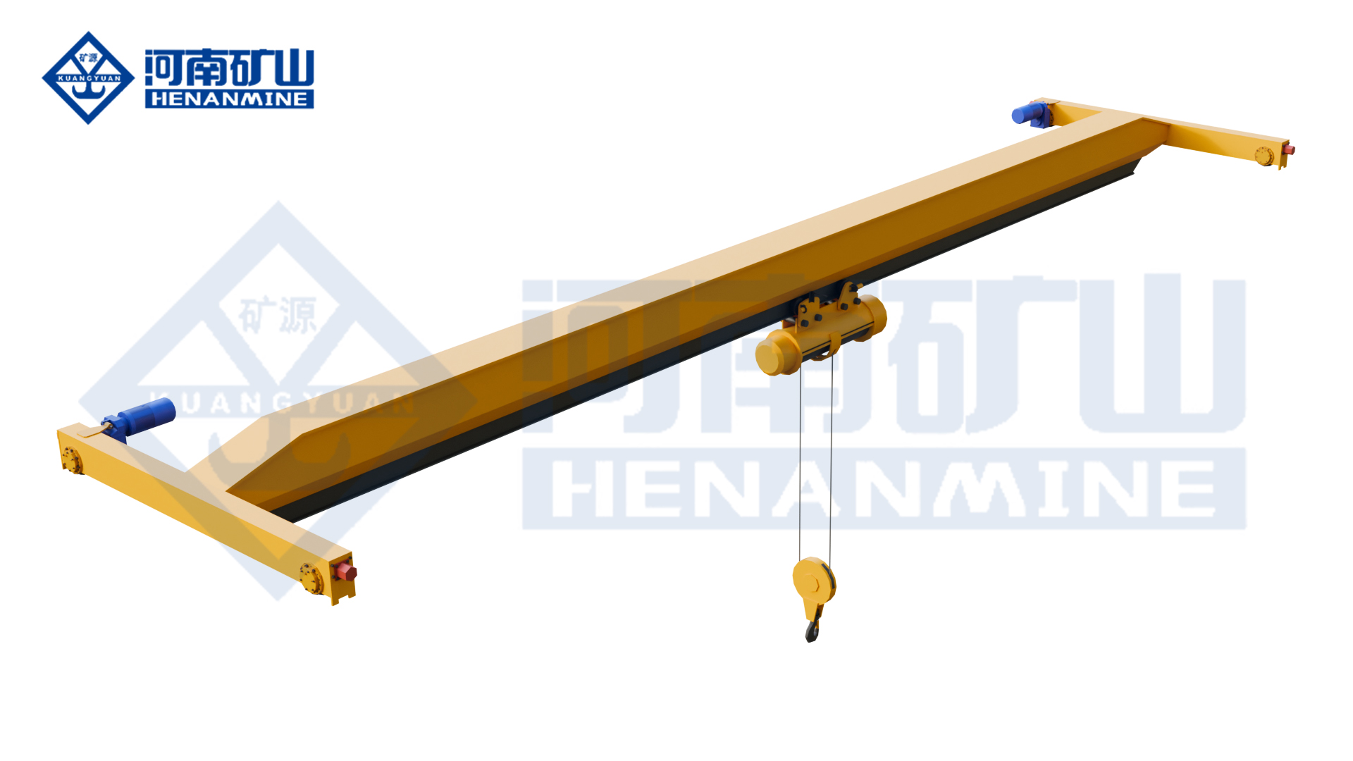
Single Girder Electric Hoist Gantry Cranes
Standard, L-leg, truss and European-style options for component transfer and loading.
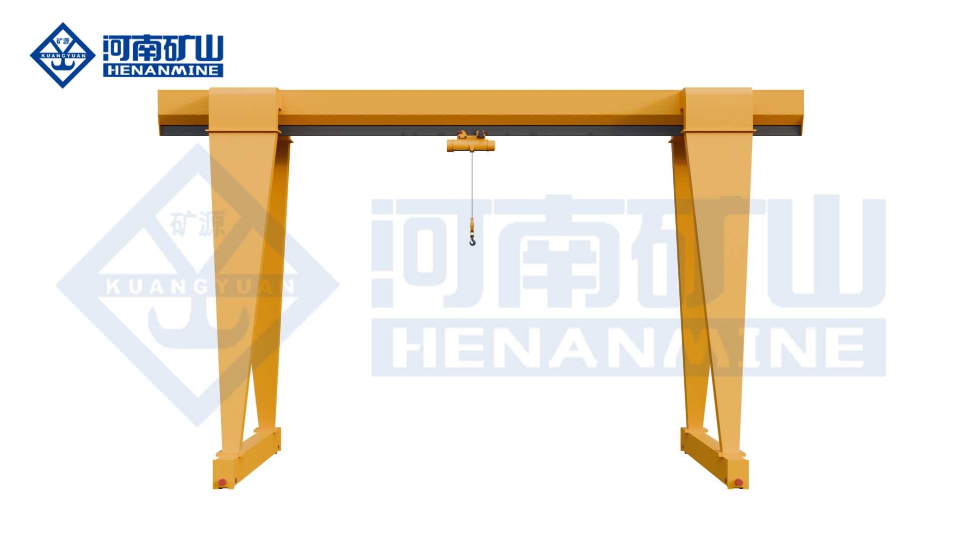
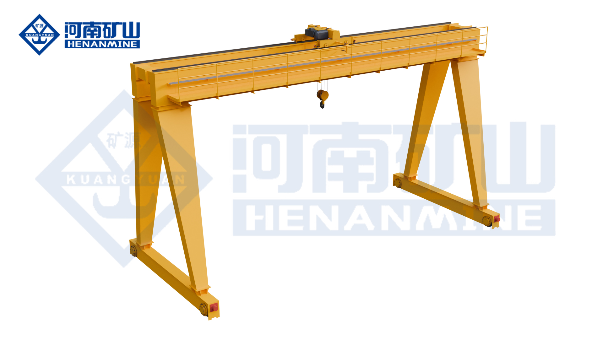
MH series
Everyday component handling and vehicle loading on two ground rails.
Capacity options 3 / 5 / 10 / 16 / 20 t
Span options 12–30 m, by capacity
Lifting height 6 m or 9 m
All specifications
Model
MH
Rated capacity
3 / 5 / 10 / 16 / 20 t
Span options
12 / 16 / 20 / 24 m; 30 m on 5–20 t configurations
Lifting height
6 m or 9 m
Working class
A3 at 3–16 t; 20 t duty selected with the HC hoist package
Girder construction
Welded box girder / full gantry
Hoist type, 3–10 t
CD1 single-speed or MD1 dual-speed wire-rope hoist
Hoist type, 16 / 20 t
CD1 at 16 t; HC at 20 t
Hoisting speed, 3 / 5 t
8 m/min or 8 / 0.8 m/min
Hoisting speed, 10 t
7 m/min or 7 / 0.7 m/min
Hoisting speed, 16 / 20 t
3.5 m/min
Hoist cross-travel speed
20 m/min
Hoist motor, 3 / 5 t
4.5 kW / 7.5 kW, single-speed hoist
Hoist motor, 10 / 16 / 20 t
13 kW / 13 kW / 18.5 kW, single-speed hoist
Hoist-travel motors, 3 / 5 t
0.4 kW / 0.8 kW
Hoist-travel motors, 10 / 16 / 20 t
2 × 0.8 kW / 2 × 0.8 kW / 4 × 0.8 kW
Runway rails, 3 / 5 t
P24 or P38, selected with span and wheel reactions
Runway rails, 10 / 16 / 20 t
P38 or P43 at 10 / 16 t; P43 or P50 at 20 t
Power supply
380 V, 50 Hz, 3-phase
Operating temperature
−20°C to +40°C for the specified equipment
Operating controls
Ground pendant / cabin; remote control by configuration
Cantilever arrangement
With or without cantilever; outside-span reach by design
Crane runway
Ground-level rails on both sides
Operating pattern
Intermittent, repeated material and component handling
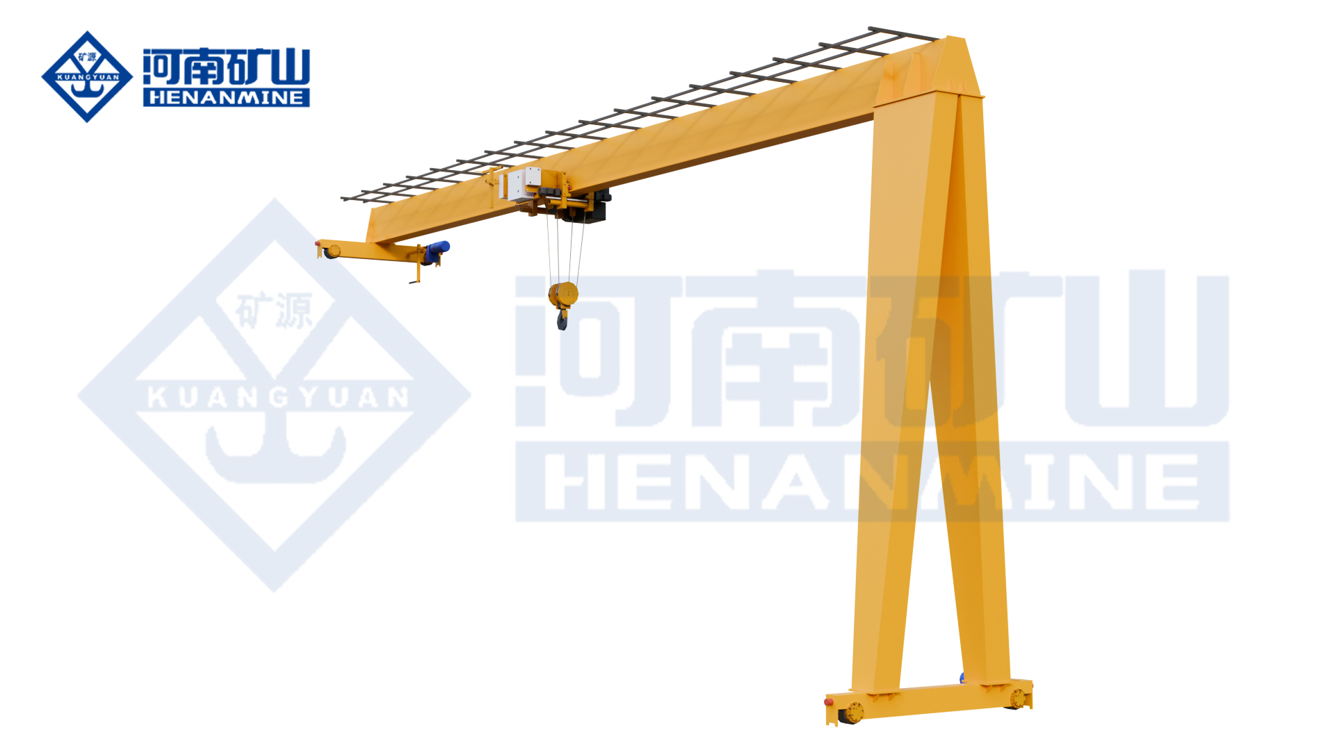
MHL series
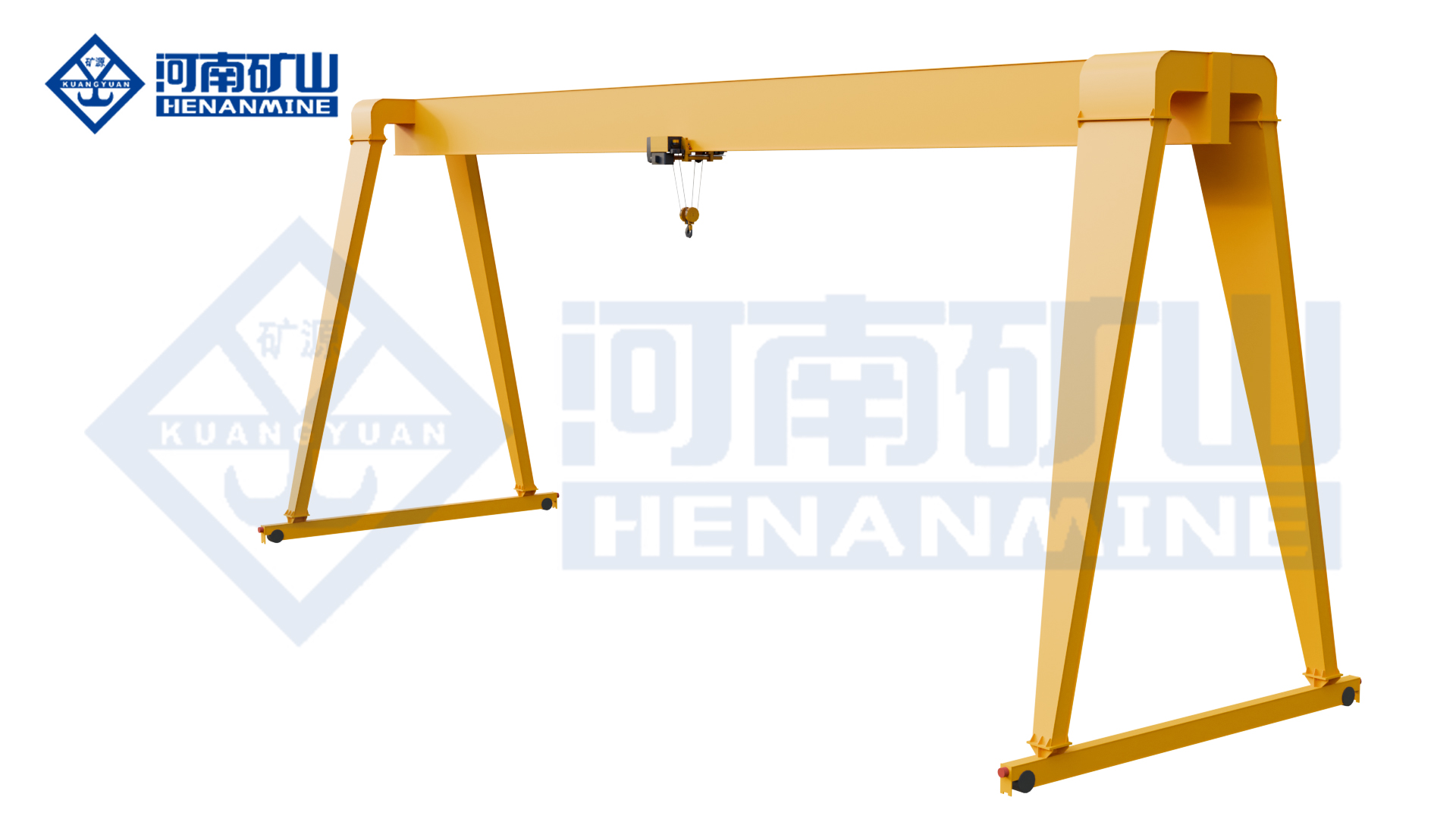
Long-load handling with L-shaped legs for side access and passage.
Capacity options 1 / 2 / 3 / 5 / 10 / 16 / 20 t
Span options 3–31.5 m
Working class A3–A5
All specifications
Model
MHL
Rated capacity options
1 / 2 / 3 / 5 / 10 / 16 / 20 t
Span options
3–31.5 m, selected with the required load
Lifting-height options
6 / 9 / 12 / 18 / 24 / 30 m
Working class
A3–A5, selected for the operating cycle
Lifting mechanism
Electric wire-rope hoist
Girder arrangement
Single girder
Supporting legs
L-shaped legs for side access and load passage
Hoisting-speed options
8 or 8 / 0.8; 7 or 7 / 0.7; 3.5 or 3.5 / 0.35 m/min
Speed selection
Choose one matched hoist speed package for the rated load
Crane-travel drive
Three-in-one variable-frequency drive
Power supply
380 V, 50 Hz, 3-phase; site supply options
Operating controls
Ground pendant / wireless remote / cabin
Lifting attachments
Hook; grab or electromagnetic attachment by configuration
Crane runway
Two ground-level runway rails
Cantilever arrangement
With or without cantilever
Clear passage
Leg opening selected for the load and vehicle route
Hook coverage
In-span lifting and agreed outside-span reach
Working motions
Vertical lifting, hoist cross travel and crane long travel
Operating pattern
Intermittent, repeated loading and material handling
Rail and wheel selection
Matched to span, wheel reactions and foundation layout
Application focus
Long loads and tasks requiring turning clearance between the legs
MHH series
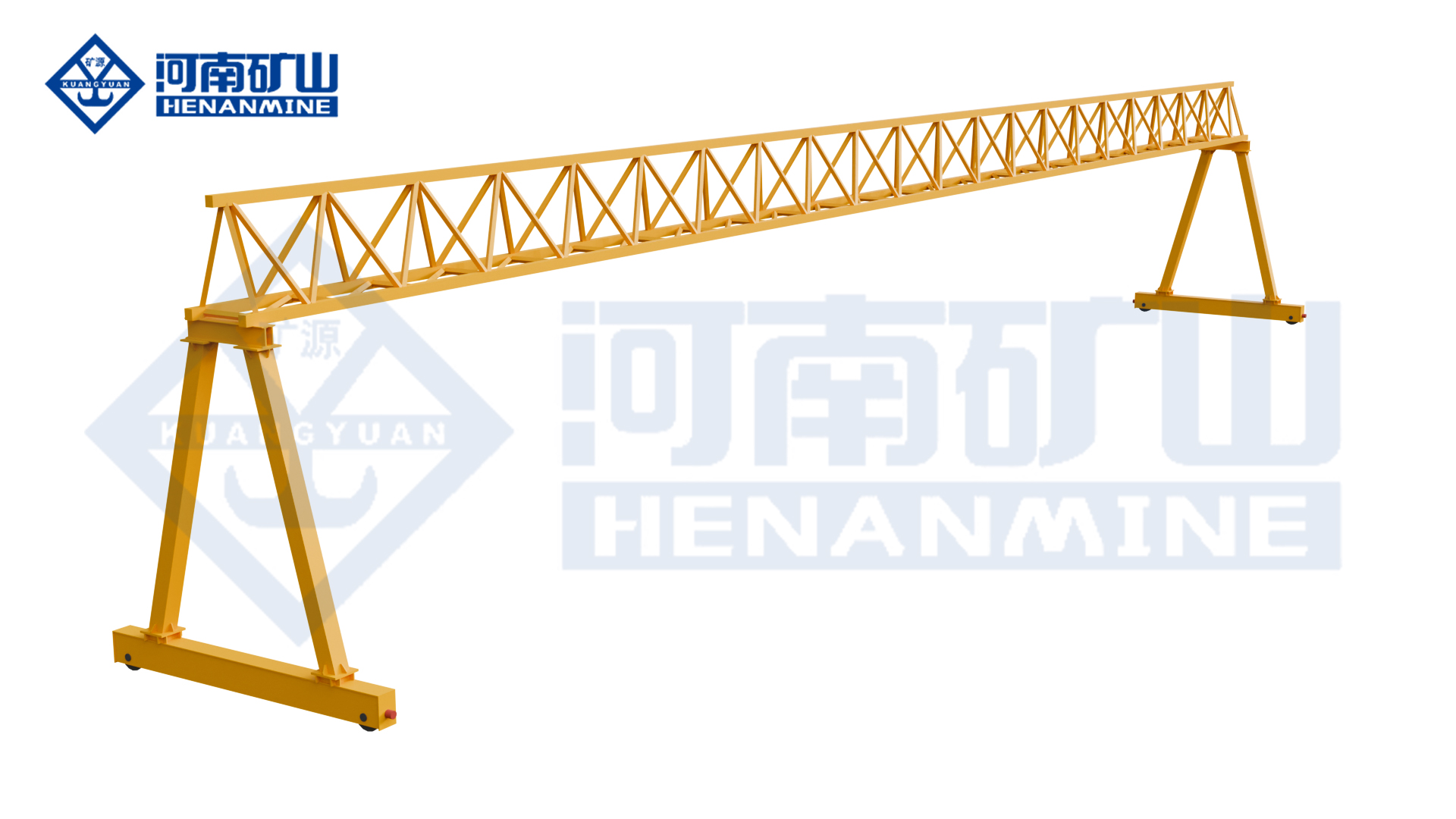
Outdoor material handling with an open-truss single-girder structure.
Capacity range 1–20 t
Span range 10–30 m
Working class A3–A5
All specifications
Model
MHH
Rated capacity range
1–20 t, with the required configuration selected together
Span range
10–30 m
Lifting-height reference
10 m; other requirements reviewed with the crane layout
Working class
A3–A5
Lifting mechanism
Electric wire-rope hoist
Main-girder structure
Open truss welded from structural steel sections
Girder arrangement
Single girder
Lifting attachments
Hook; grab or electromagnetic attachment by configuration
Crane runway
Ground-level rails on both sides
Cantilever arrangement
With or without cantilever
Structural selection
Truss sections matched to load, span and local wind exposure
Power supply
380 V, 50 Hz, 3-phase
Operating control
Ground control for the reference arrangement
Hoisting speed
Specified with the selected load and electric-hoist package
Cross travel
Powered electric-hoist travel along the girder
Long travel
Rail travel selected for the runway length and handling cycle
Frame alternatives
Fixed or travelling arrangements; bogie options by design
Working motions
Vertical lifting and movement across / along the runway
Operating pattern
Intermittent, repeated material and equipment handling
Transport arrangement
Girder sections and assembly joints selected for delivery access
Application focus
Outdoor handling where truss structure and wind exposure matter
KSMH series
Component lifting and positioning with a new-design wire-rope hoist.
Capacity options 5–20 t; 30 t by design
Span options 10–30 m
Working class A5 reference
All specifications
Model
KSMH
Rated capacity options
5 / 10 / 16 / 20 t; 30 t configuration by design
Span options
10–30 m; custom span by design
Lifting-height options
6 / 9 / 12 / 15 m; custom lift by design
Working class
A5 for the reference configuration
Hoist type
New-design European-style wire-rope electric hoist
Girder arrangement
Single girder / full gantry
Hoisting-speed reference
7 m/min; selected for the load and working cycle
Travel-speed reference
20 m/min; final mechanism speeds in the equipment schedule
Positioning configuration
Hoist and travel controls selected for pickup and set-down tasks
Power supply
380 V, 50 Hz, 3-phase; site supply options
Operating controls
Pendant buttons / wireless remote, by configuration
Crane runway
Two ground-level rails
Cantilever arrangement
With or without cantilever
Lifting attachments
Hook; grab or electromagnetic attachment by configuration
Working motions
Vertical lifting, hoist cross travel and crane long travel
Load-dependent operation
Heavy-load slow / light-load fast operation with the selected package
Core-component layout
Modular design with replaceable wheels and couplings
Headroom and approach
Hoist envelope and upper hook position checked against the bay
Rail and foundation interface
Selected wheel reactions and rail geometry define the civil interface
Operating pattern
Intermittent, repeated loading and material handling
Application focus
Workshop and yard tasks comparing a new-design hoist package
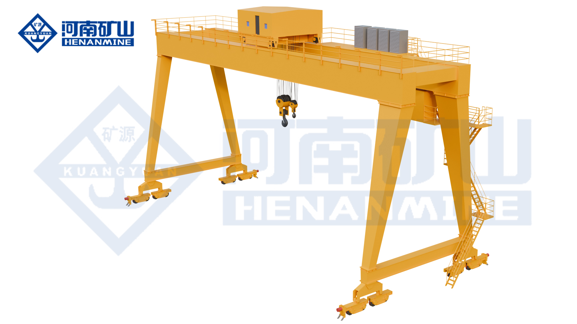
Double Girder Electric Hoist Gantry Cranes
Two-girder layouts with an electric-hoist lifting package for production and yard handling.
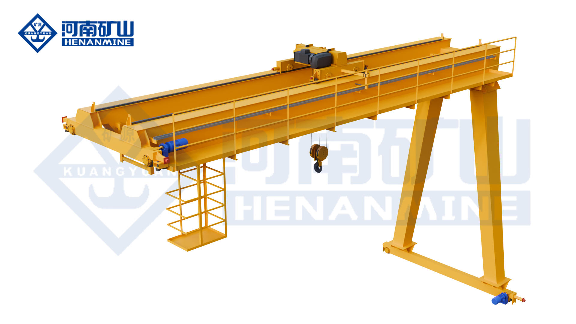
MHS series
Double-girder electric-hoist lifting for yard loading and component transfer.
Capacity range 3–50 t
Span range 7.5–35 m
Lifting height 4–30 m
All specifications
Model
MHS
Rated lifting capacity
3–50 t
Span
7.5–35 m
Lifting height
4–30 m
Girder arrangement
Double girder
Runway/support layout
Full gantry; ground rails on both sides
Lifting mechanism
Electric hoist
Hoist/trolley arrangement
Seated electric-hoist trolley
Lifting attachment
Hook
Working class
A-class selected for the load spectrum and operating cycle
Lifting speed
Lifting and positioning speeds matched to the selected electric hoist
Trolley travel speed
Cross-travel speed and stopping control selected for the load route
Crane travel speed
Long-travel speed selected for the runway and operating cycle
Travel drive
Motor / gearbox / brake package matched to duty and wheel reactions
Operating controls
Pendant / wireless remote / cabin options
Cantilever arrangement
With or without cantilever
Electrical supply
380 V / 50 Hz; 220–660 V / 50–60 Hz supply options
Electrical protection
IP54 option; protected equipment scope defined in the electrical schedule
Runway rail profile
Rail section matched to wheel geometry, reactions and supporting structure
Motor ratings
Lifting, trolley and crane-travel motor ratings specified in the equipment schedule
Operating pattern
Intermittent, repeated loading/unloading and material handling
Site layout
Overall height, leg clearance and hook approach shown in the crane drawing
KSMHS series
Top-running electric-hoist lifting with variable-speed hoisting and travel.
Hoist arrangement Top-running electric-hoist trolley
Motion control Variable-frequency lifting & travel
Working class A3–A5
All specifications
Model
KSMHS
Rated lifting capacity
Selected for the complete suspended load, including rigging
Span
Rail-centre span selected for the working area
Lifting height
Hook travel and headroom selected for pickup / set-down levels
Girder arrangement
Double girder
Runway/support layout
Full gantry; ground rails on both sides
Lifting mechanism
Electric hoist
Hoist/trolley arrangement
Top-running electric-hoist trolley
Lifting attachment
Hook / grab / electromagnetic lifting configurations
Working class
A3–A5
Lifting speed
Lifting and positioning speeds matched to the selected electric hoist
Trolley travel speed
Cross-travel speed and stopping control selected for the load route
Crane travel speed
Long-travel speed selected for the runway and operating cycle
Travel drive / motion control
Variable-frequency lifting and travel
Operating controls
Operator control package selected for visibility and the lifting task
Cantilever arrangement
With or without cantilever
Electrical supply
Site voltage, phases, frequency and power feed matched in the electrical package
Electrical connectors
Heavy-duty electrical plug connectors: IP55
Runway rail profile
Rail section matched to wheel geometry, reactions and supporting structure
Motor ratings
Lifting, trolley and crane-travel motor ratings specified in the equipment schedule
Operating pattern
Intermittent, repeated loading/unloading and material handling
Speed adjustment ratio
1:10
Electric Hoist Semi Gantry Cranes
One ground rail and one elevated runway for lifting alongside a workshop structure.
MB₁ series
Double-girder lifting alongside a building-supported runway and floor rail.
Support layout Elevated runway + floor rail
Girder layout Double girder
Working class A3–A5
All specifications
Model
MB₁
Rated lifting capacity
Selected for the complete suspended load, including rigging
Span
Rail-centre span selected for the working area
Lifting height
Hook travel and headroom selected for pickup / set-down levels
Girder arrangement
Double girder
Runway/support layout
Semi-gantry; one elevated runway and one ground rail
Lifting mechanism
Electric hoist
Hoist/trolley arrangement
Electric-hoist trolley on twin girders
Lifting attachment
Hook / grab / electromagnetic lifting configurations
Working class
A3–A5
Lifting speed
Lifting and positioning speeds matched to the selected electric hoist
Trolley travel speed
Cross-travel speed and stopping control selected for the load route
Crane travel speed
Long-travel speed selected for the runway and operating cycle
Travel drive / motion control
Three-in-one direct-connected crane and trolley travel drives
Operating controls
Pendant / wireless remote; cabin or PLC-linked control by configuration
Cantilever arrangement
With or without cantilever
Electrical supply
Site voltage, phases, frequency and power feed matched in the electrical package
Electrical protection
Cabinet, motor and connector protection selected for the environment
Runway rail profile
Rail section matched to wheel geometry, reactions and supporting structure
Motor ratings
Lifting, trolley and crane-travel motor ratings specified in the equipment schedule
Operating pattern
Intermittent, repeated loading/unloading and material handling
Site layout
Overall height, leg clearance and hook approach shown in the crane drawing
KSMB series
Single-girder semi-gantry lifting for workshop loading and material transfer.
Capacity range 1–32 t
Span range 6–35 m
Lifting height 4–20 m
All specifications
Model
KSMB
Rated lifting capacity
1–32 t
Span
6–35 m
Lifting height
4–20 m
Girder arrangement
Single girder
Runway/support layout
Semi-gantry; one elevated runway and one ground rail
Lifting mechanism
Electric hoist
Hoist/trolley arrangement
European-style electric hoist; suspended travel arrangement shown
Lifting attachment
Hook / grab / electromagnetic chuck options
Working class
A3–A5
Lifting speed
Lifting and positioning speeds matched to the selected electric hoist
Trolley travel speed
Cross-travel speed and stopping control selected for the load route
Crane travel speed
Long-travel speed selected for the runway and operating cycle
Travel drive / motion control
Three-in-one direct-connected travel drive; variable-frequency lifting/travel
Operating controls
Cabin / pendant / wireless remote / PLC linkage options
Cantilever arrangement
With or without cantilever
Electrical supply
380 V / 50 Hz; 220–660 V / 50–60 Hz supply options
Electrical protection
IP54 option; protected equipment scope defined in the electrical schedule
Runway rail profile
Rail section matched to wheel geometry, reactions and supporting structure
Motor ratings
Lifting, trolley and crane-travel motor ratings specified in the equipment schedule
Operating pattern
Intermittent, repeated loading/unloading and material handling
Speed adjustment ratio
1:10
Reducer gear tooth hardness
≥60 HRC
Site layout
Overall height, leg clearance and hook approach shown in the crane drawing
MBES series
Double-girder semi-gantry handling with a new-design electric-hoist package.
Support layout Elevated runway + floor rail
Girder layout Double girder
Working class A3–A5
All specifications
Model
MBES
Rated lifting capacity
Selected for the complete suspended load, including rigging
Span
Rail-centre span selected for the working area
Lifting height
Hook travel and headroom selected for pickup / set-down levels
Girder arrangement
Double girder
Runway/support layout
Semi-gantry; one elevated runway and one ground rail
Lifting mechanism
Electric hoist
Hoist/trolley arrangement
Top-running electric-hoist trolley
Lifting attachment
Hook / grab / electromagnetic lifting configurations
Working class
A3–A5
Lifting speed
Lifting and positioning speeds matched to the selected electric hoist
Trolley travel speed
Cross-travel speed and stopping control selected for the load route
Crane travel speed
Long-travel speed selected for the runway and operating cycle
Travel drive / motion control
Three-in-one direct-connected crane and trolley travel drives
Operating controls
Pendant / wireless remote options
Cantilever arrangement
With or without cantilever
Electrical supply
Site voltage, phases, frequency and power feed matched in the electrical package
Electrical protection
Cabinet, motor and connector protection selected for the environment
Runway rail profile
Rail section matched to wheel geometry, reactions and supporting structure
Motor ratings
Lifting, trolley and crane-travel motor ratings specified in the equipment schedule
Operating pattern
Intermittent, repeated loading/unloading and material handling
Site layout
Overall height, leg clearance and hook approach shown in the crane drawing
Grab and Explosion Proof Hoist Gantry Cranes
Material-specific lifting for loose bulk cargo or classified hazardous environments.
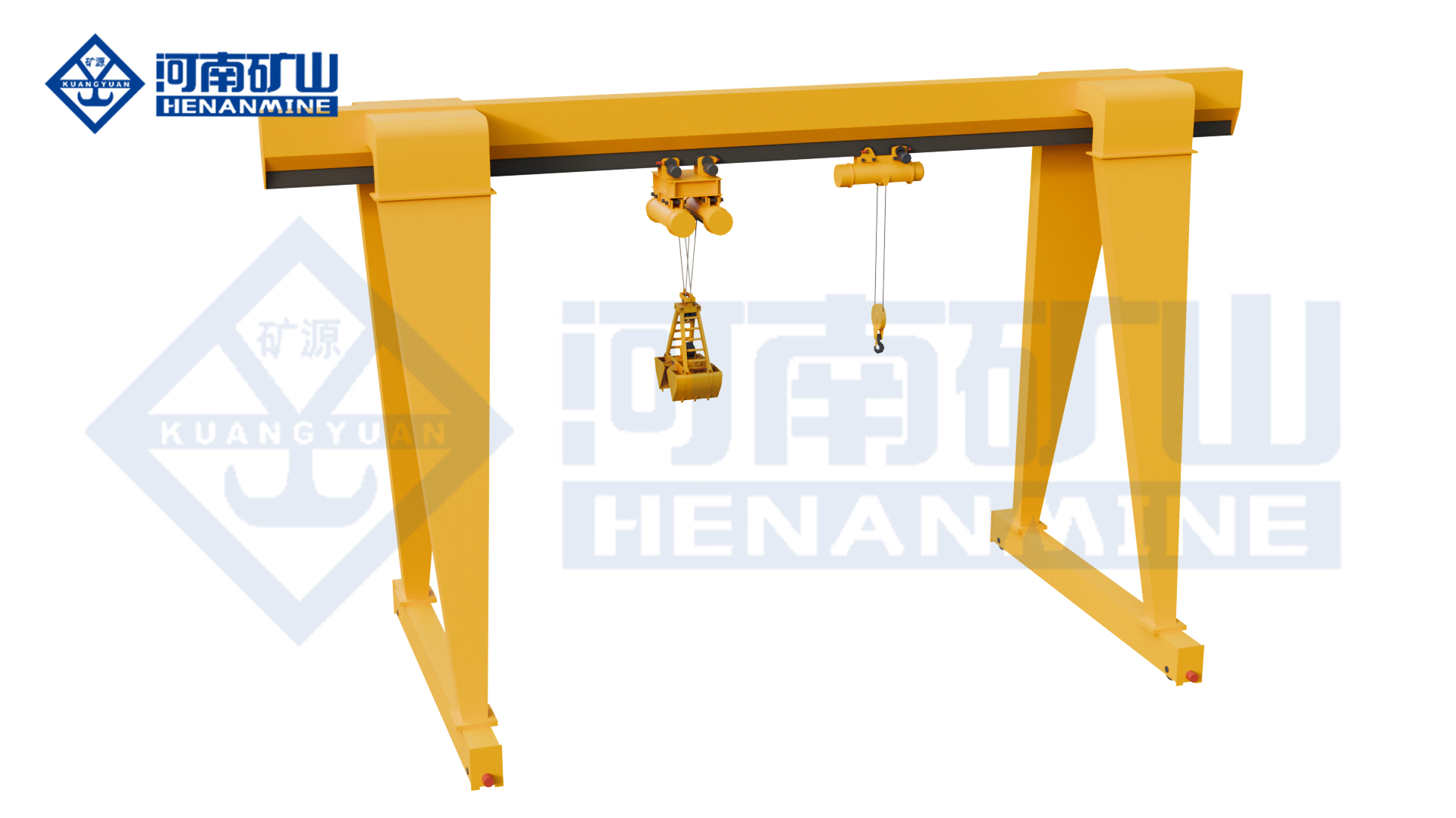
MHZE series
Grab-and-hook lifting for loose bulk material and general cargo.
Handling modes Grab and hook
Attachment interface Dedicated quick connection
Rated load Specified for each handling mode
All specifications
Model
MHZE
Lifting system
Electric-hoist gantry arrangement
Handling modes
Grab for bulk material; hook for general cargo
Attachment changeover
Dedicated quick-connection mechanism for grab / hook exchange
Grab application
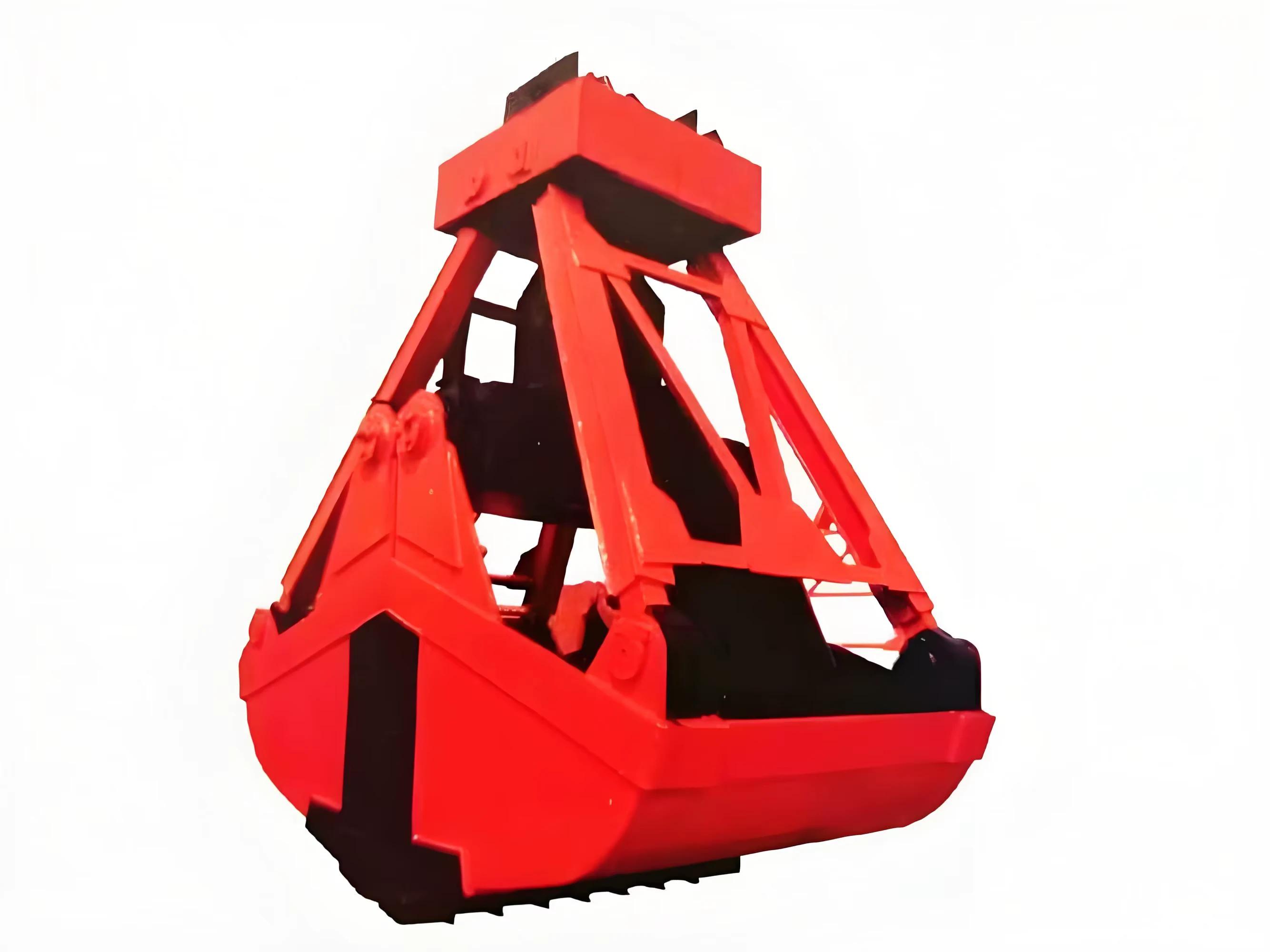
Bulk material such as coal or ore; select the grab for your material
Hook application
Components and general cargo handled by hook
Rope-grab arrangement
Coordinated supporting and opening / closing ropes, where specified
Grab actuation
Hydraulic or mechanical, selected with the grab package
Grab opening / closing
3–5 s for the matched grab configuration; confirm material and operating conditions
Hook-mode load
Rate for the complete hook-lifted load, including slings and lifting attachments
Grab-mode suspended load
Check grab self-weight plus the material carried and connecting equipment
Grab volume and material
Select from material density, particle size and required load per cycle
Duty and cycle
Define lifts per hour, shifts and load spectrum for both handling modes
Span and runway
Set rail-centre span and travel length from the loading / discharge route
Usable lifting height
Specify pickup level, discharge height and the selected grab's closed height
Lifting speed
Quote loaded and positioning speeds for the selected attachment and duty
Trolley and crane travel
Select travel speed and stopping control for the loading and discharge positions
Wheel manufacture
Forging and rolling combined process
Transmission coupling
Crowned gear coupling
Maintenance arrangement
Modular design with replaceable core components
Operating control
Operator position and grab / hook control functions selected for the work area
Power interface
Site voltage, frequency and phases; separate grab power / control interface where required
BMH series
Hook lifting for sites requiring an assessed explosion-protection package.
Hoisting equipment Explosion-proof electric hoist
Support layout Two ground-level rails
Working class A3
All specifications
Model
BMH
Working class
A3
Lifting mechanism
Explosion-proof electric hoist
Lifting attachment
Hook
Crane support and runway
Two supporting leg frames running on ground rails
Working motions
Hoisting, hoist cross travel and crane long travel
Cantilever arrangement
With or without cantilever; specify the outside-span lifting reach
Operating control
Cab, ground or remote arrangement
Operating pattern
Intermittent, repeated loading and material handling
Crane-travel drive layout
Vertically arranged travel gearing
Rated suspended load
Select for the heaviest complete hook load, rigging and attachment
Rail-centre span
Define from the two runway lines and required hook coverage
Lifting height and hook reach
State pickup / set-down levels, upper hook position and approach limits
Hoisting speed
Match lifting and positioning speed to the selected protected hoist
Trolley and crane speeds
Specify loaded travel, approach speed and stopping needs
Site power supply
Provide voltage, frequency, phases and power-feed arrangement
Hazardous-area classification
State hazardous medium, zone, gas / dust group and temperature requirement
Protection package
Define the hoist, travel equipment, controls and accessories for the same area
Applicable standard and documents
Agree destination standard, equipment marking and model-specific protection documents
Rails and foundation interface
Request final rail section, wheel reactions and foundation / outdoor load cases
Capacity, span, lifting height, duty and speeds are selected together. Include all suspended lifting attachments and rigging in the load.
Budget planning
Electric-hoist gantry crane price guide
Plan the crane equipment budget around capacity, span and useful lifting height. The ranges below assume a standard rail-mounted hook crane with an electric wire rope hoist, powered travel and pendant control.
Preliminary equipment budget · USD per crane · 26 October 2026 Planning configuration Budget range · USD
5 t single-girder electric-hoist gantry · 10–15 m span · 6 m lift US$9,000–16,000 5 t single-girder electric-hoist gantry · 20–30 m span · 6–9 m lift US$14,000–24,000 10 t single-girder electric-hoist gantry · 15–25 m span · 6–9 m lift US$17,000–30,000 20 t electric-hoist gantry · 15–25 m span · 6–9 m lift US$28,000–48,000
These are preliminary planning estimates for the crane steelwork, hoist and trolley, travel drives, electrical controls and technical documents. They are not firm quotations or installed prices. The selected girder, support arrangement, duty and wheel loads must be confirmed together in the technical offer.
Runway rails, foundations, civil work, building supports, site power feed, freight, import duties, taxes, erection and commissioning are excluded. Cantilevers, higher duty, outdoor wind design, anti-corrosion treatment, variable-frequency drives and explosion protection can place the package outside these ranges. Semi-gantries require a separate building-interface and equipment quotation.
Get a quote for your configuration
Illustrative selection example
Sizing a crane for fabricated components
A 4.6 t component plus 0.25 t of complete below-hook lifting gear creates a 4.85 t suspended load. A 5 t capacity is a starting point for evaluation; lifting frequency and the selected hoist duty still need review.
The next checks are useful hook coverage, load passage between the legs, pickup height and outdoor conditions. Two ground rails suit a full gantry; one elevated runway calls for a semi-gantry assessment. This is a selection example, not a completed customer project.
Discuss your lifting layout
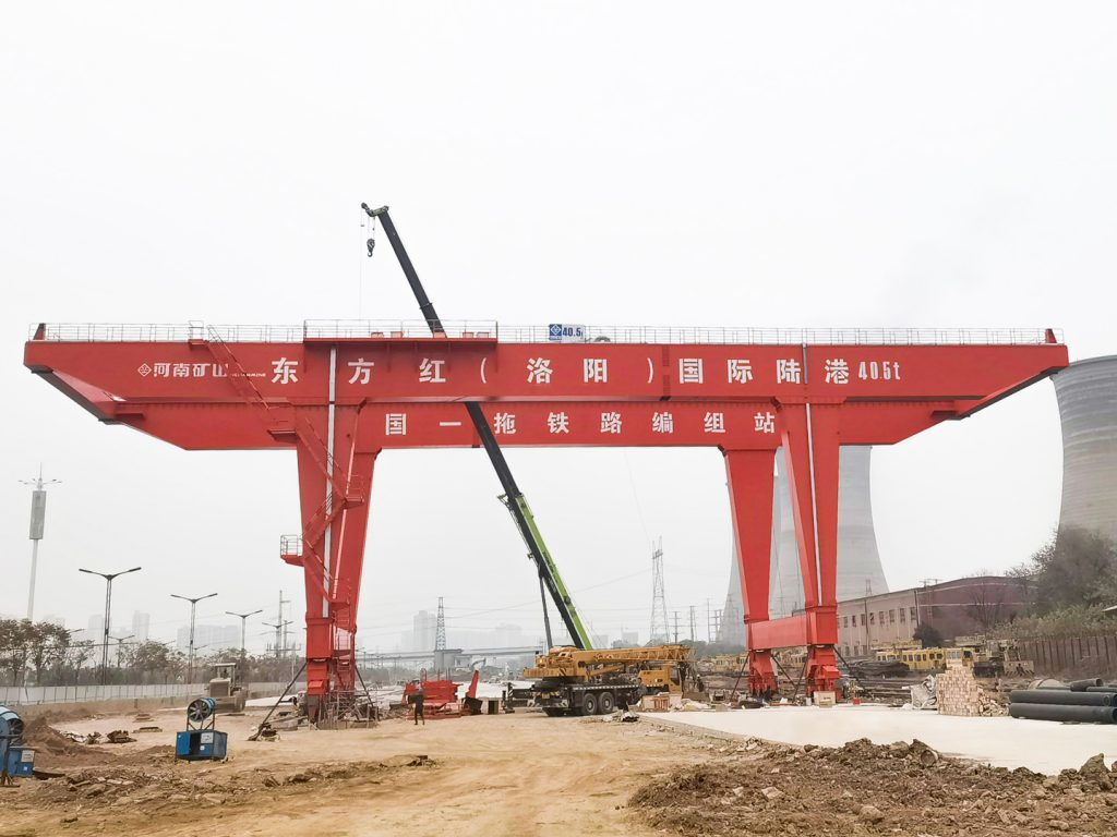
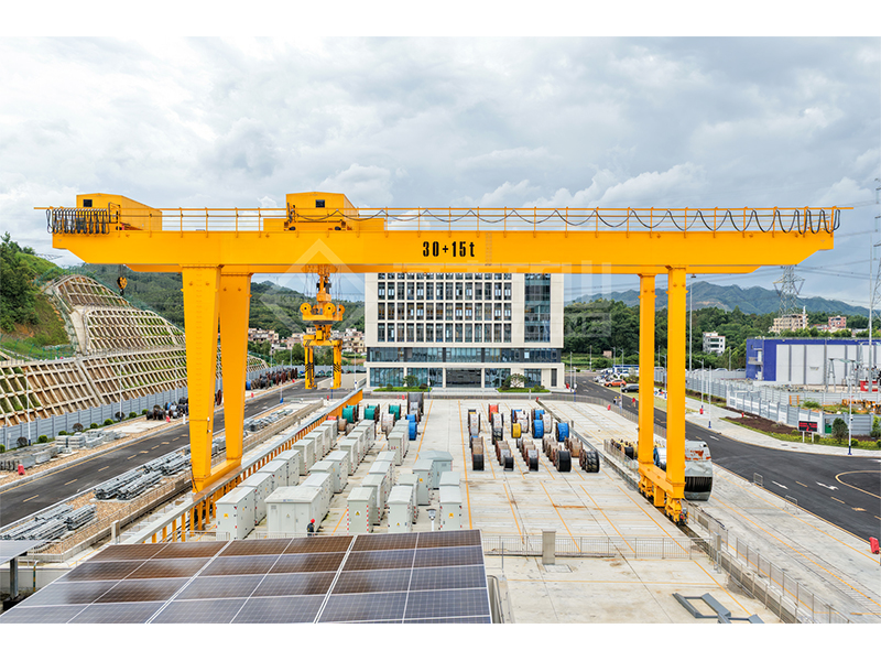
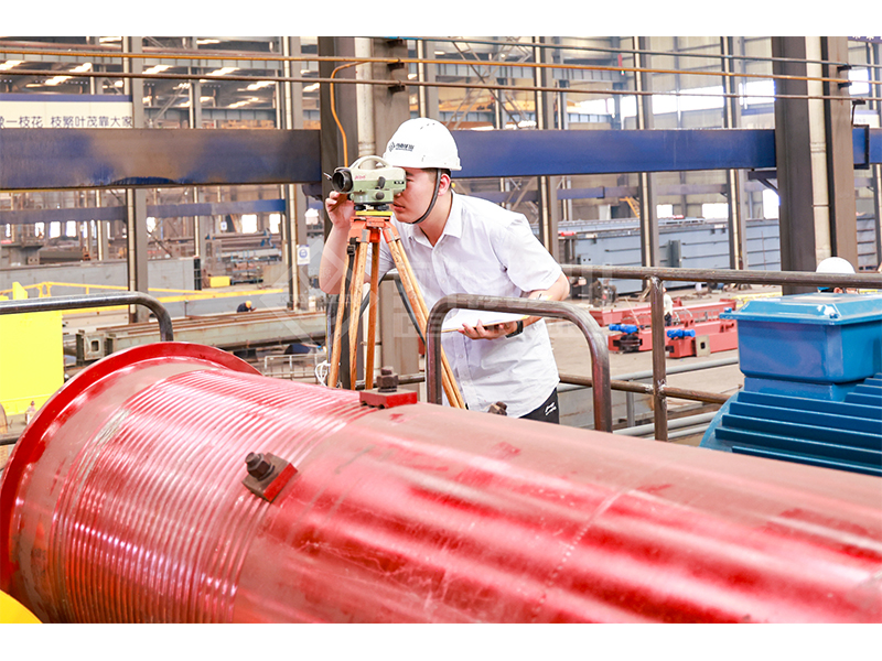
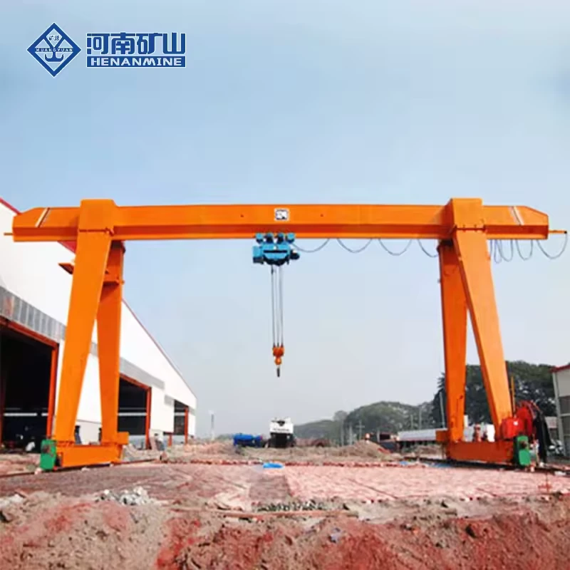
MH series photograph for layout reference; not a photograph of the illustrative selection example.
Electric-hoist gantry crane buying questions
Which electric-hoist gantry crane layout fits my site?
Full gantries run on two ground rails. Semi gantries use one ground rail and one elevated runway. L-leg layouts provide a different side opening; compare the loaded hook path, leg clearance and vehicle route.
How do I choose the lifting capacity?
Add the heaviest workpiece, lifting beam, grab or other attachment, and all suspended rigging. Select the crane and hoist for that complete load, then confirm duty from lift frequency and shifts.
Are all listed capacities, spans and heights available together?
No. Published options describe the model range. The quotation and drawing confirm one compatible capacity, span, lift, speed and duty combination, including hook approaches and wheel loads.
What must be specified for an explosion proof gantry crane?
Provide the hazardous-area classification, gas or dust group, temperature class and ambient conditions. The BMH package and certification scope must match that classification; an explosion proof hoist alone does not define the suitability of the complete crane.
What information is needed for an accurate quotation?
Send the total suspended load, rail-centre span, useful hook height, runway length, lifts per hour, power supply and destination. Add any cantilever reach, outdoor exposure, building support or special attachment requirements.
Compare the range
Electric-hoist gantry crane specification comparison
Compare the layout, capacity, span, useful lifting height and duty. Select a full product name to view its details.
Swipe across the table to compare specifications.
Ranges and catalogue options are not a promise of every possible combination. The technical offer confirms the selected equipment, dimensions, operating conditions and supply scope.
Get an electric-hoist gantry crane quote
Send the load, span, useful lifting height and destination. Add a site sketch and operating cycle if available.
The offer should identify the hoist package, crane structure, rails, power feed, delivery terms and site-service responsibilities.
Request a quotation