
Load and hoist package
Select CD1 single-speed or MD1 normal-and-creep lifting for 3–10 t, CD1 for 16 t and HC for 20 t. Match the speed, motor and rail package to its capacity row; include rigging in the suspended load.
Bridge cranes for workshops and production lines.
Explore Overhead Cranes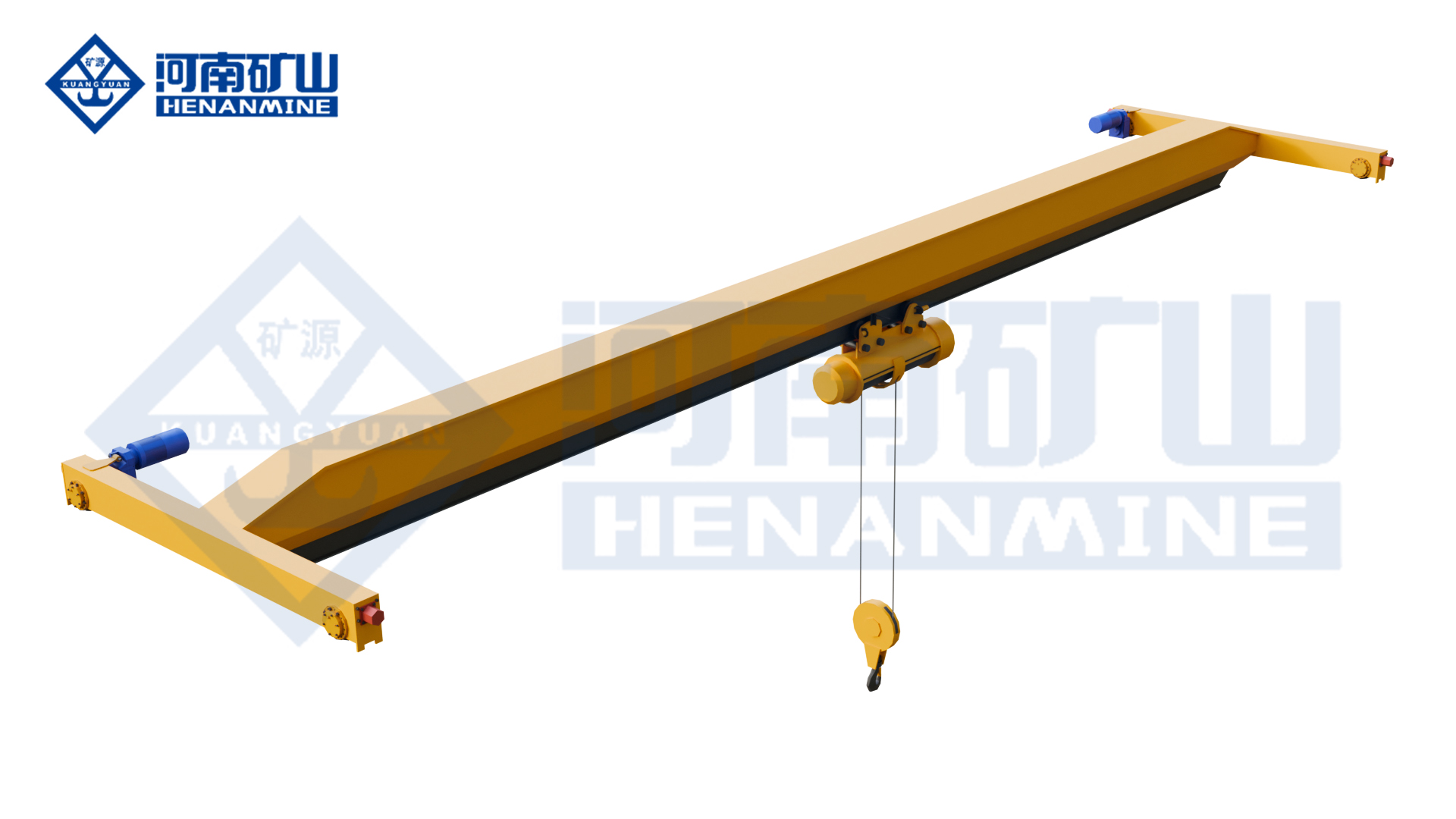
Ground-supported lifting for yards and construction.
Explore Gantry Cranes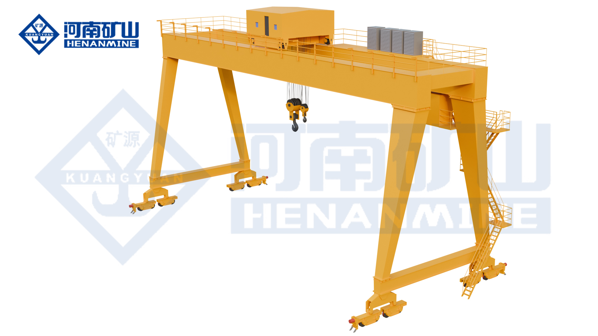
Wire rope and chain hoists for lifting points and cranes.
Explore Electric Hoists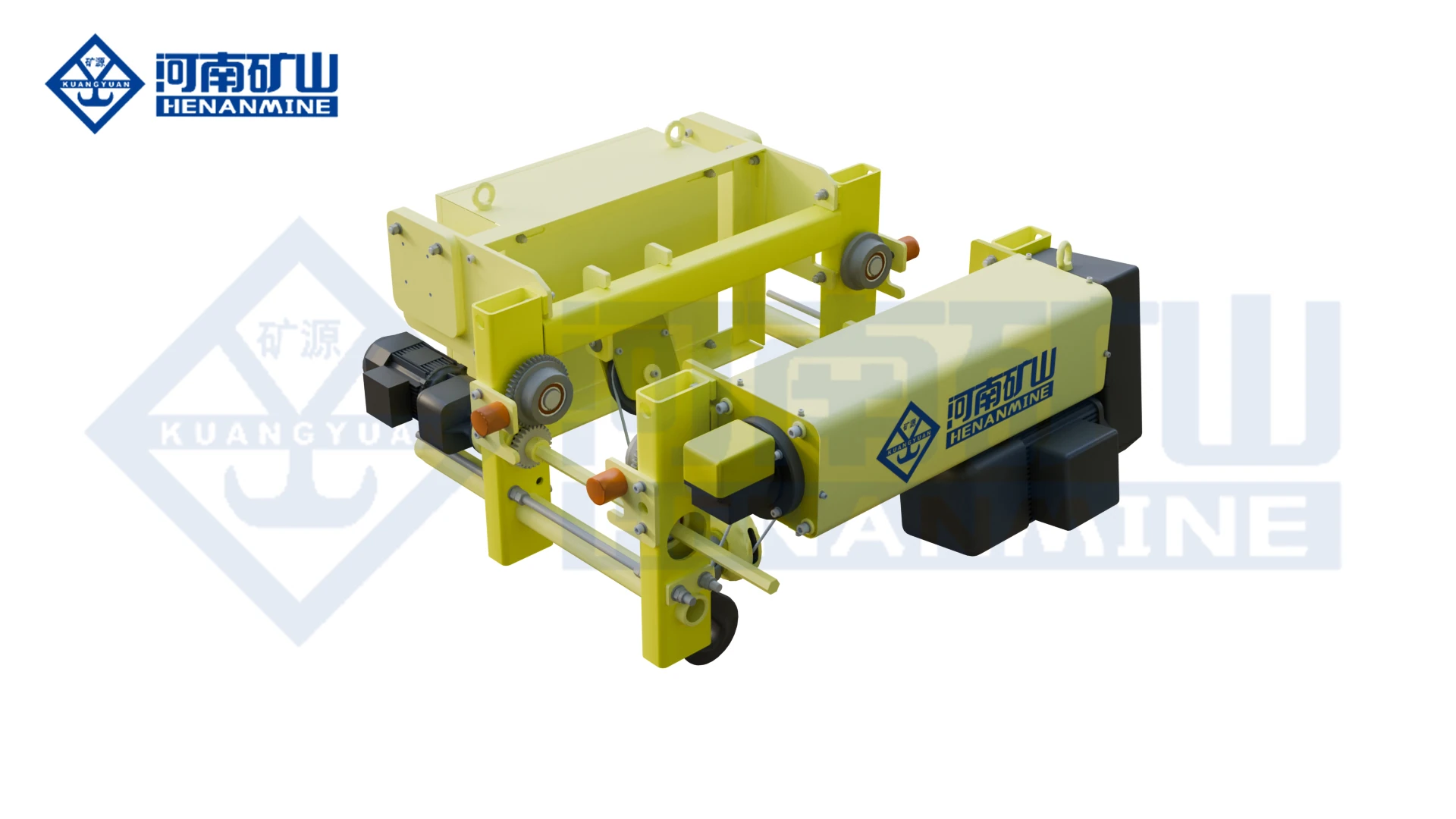
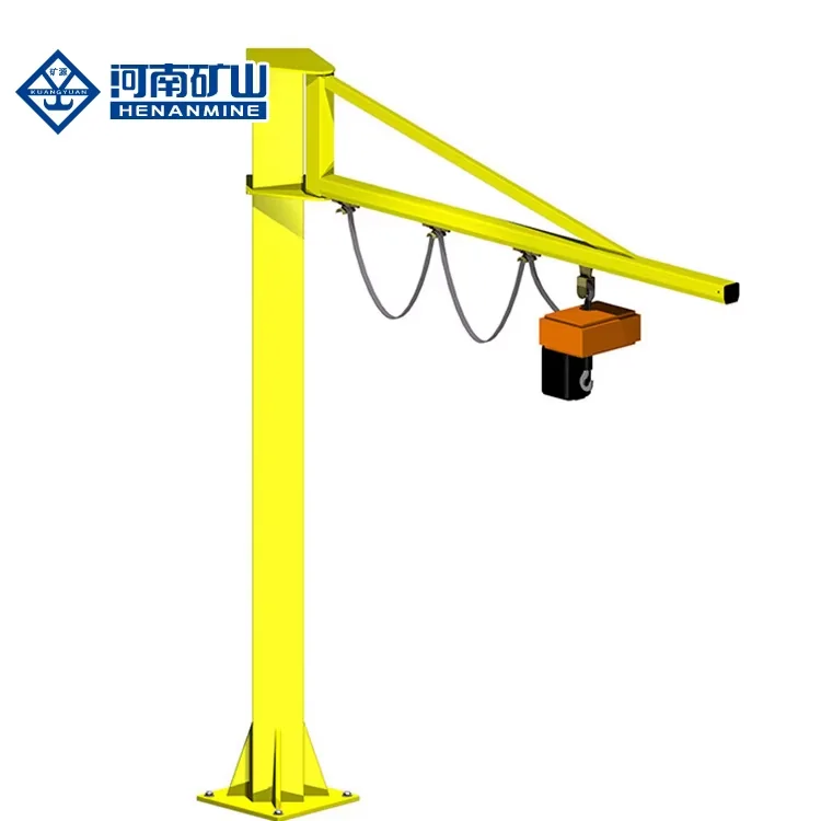
Wire rope lifting and pulling with a powered drum.
Explore Electric Winches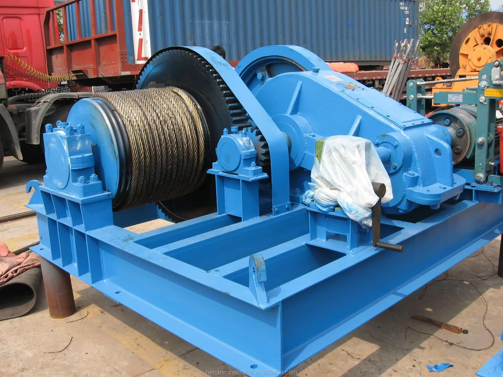
Grab buckets, magnets and hooks for your load.
Explore Lifting Attachments & Grabs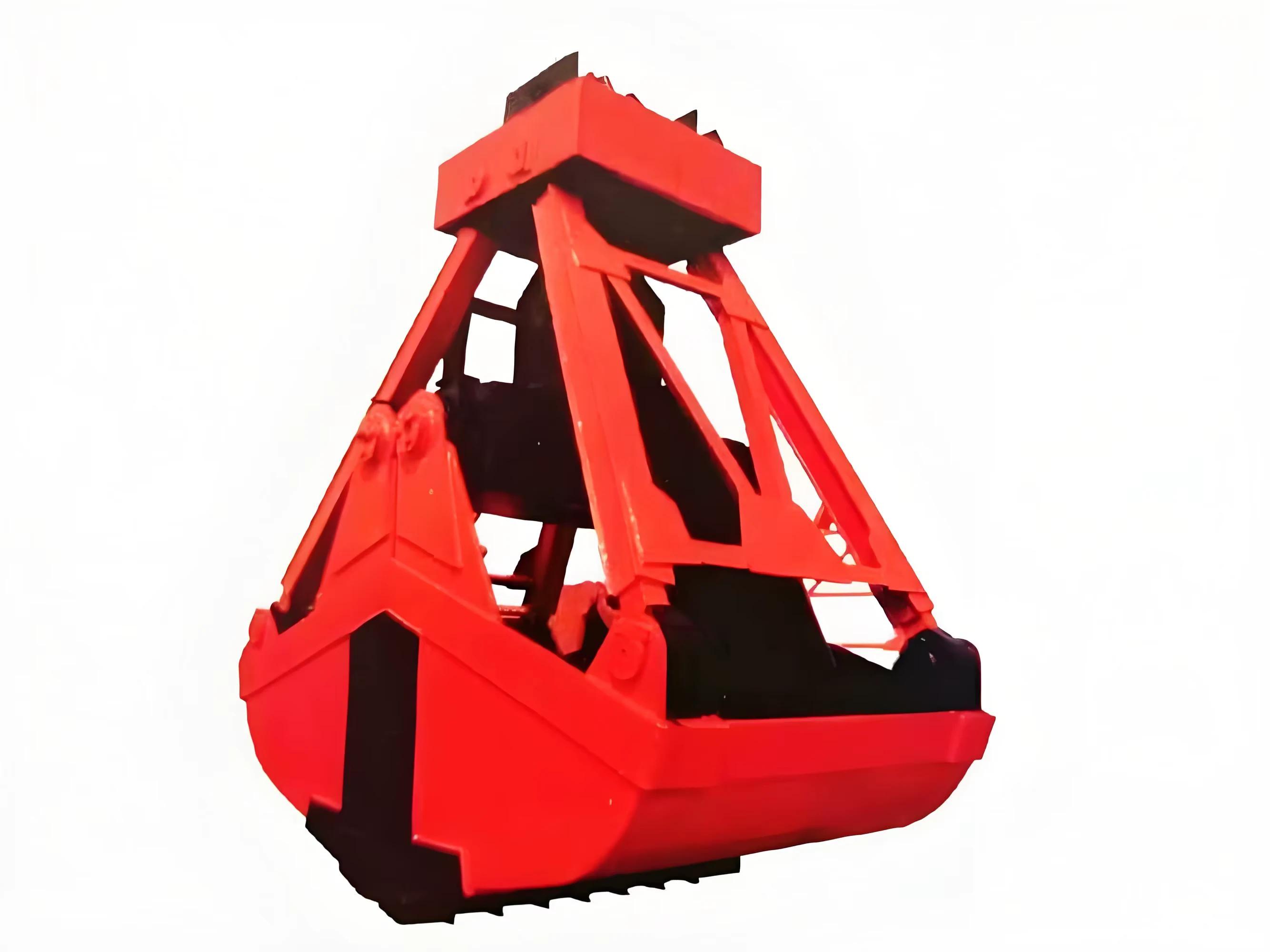
Mobile handling for containers, precast and yard loads.
Explore Rubber-Tired Gantry Cranes & Straddle Carriers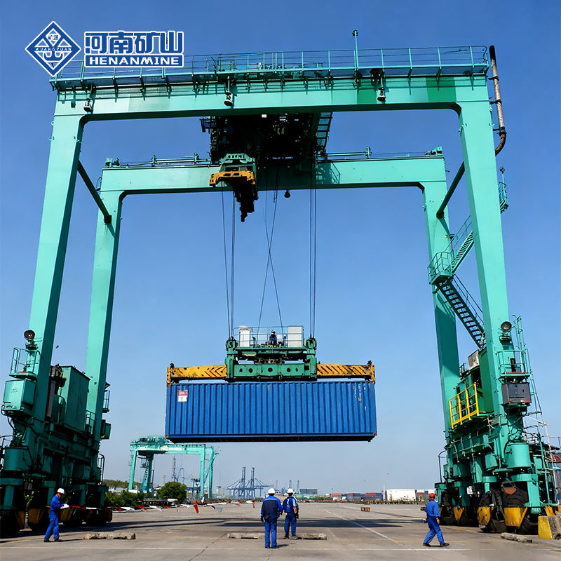
Lift and move vessels through boatyards and marinas.
Explore Marine Travel Lifts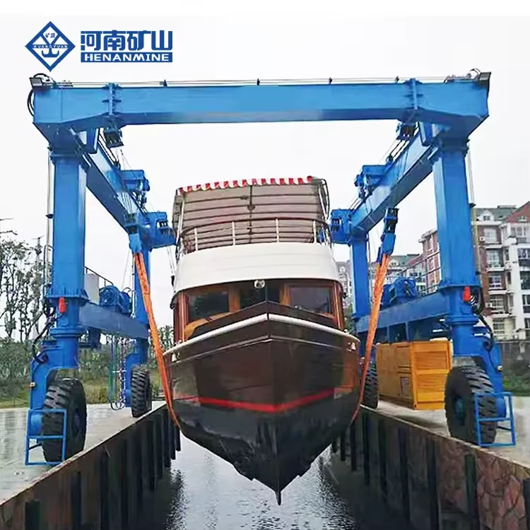
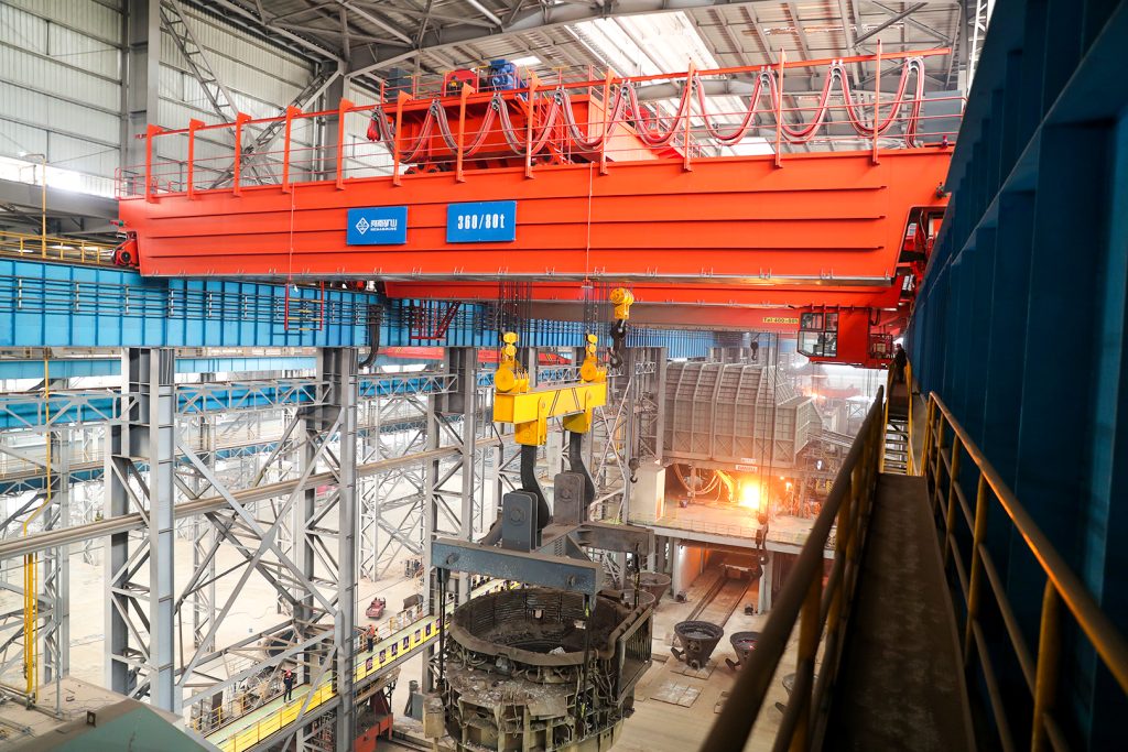
Ladle, slab, scrap and coil handling across steel production.
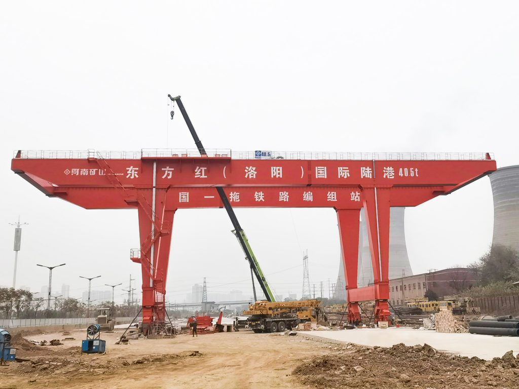
Container stacking and cargo transfers across terminals and rail.
Turbine installation, powerhouse maintenance and wind equipment assembly.
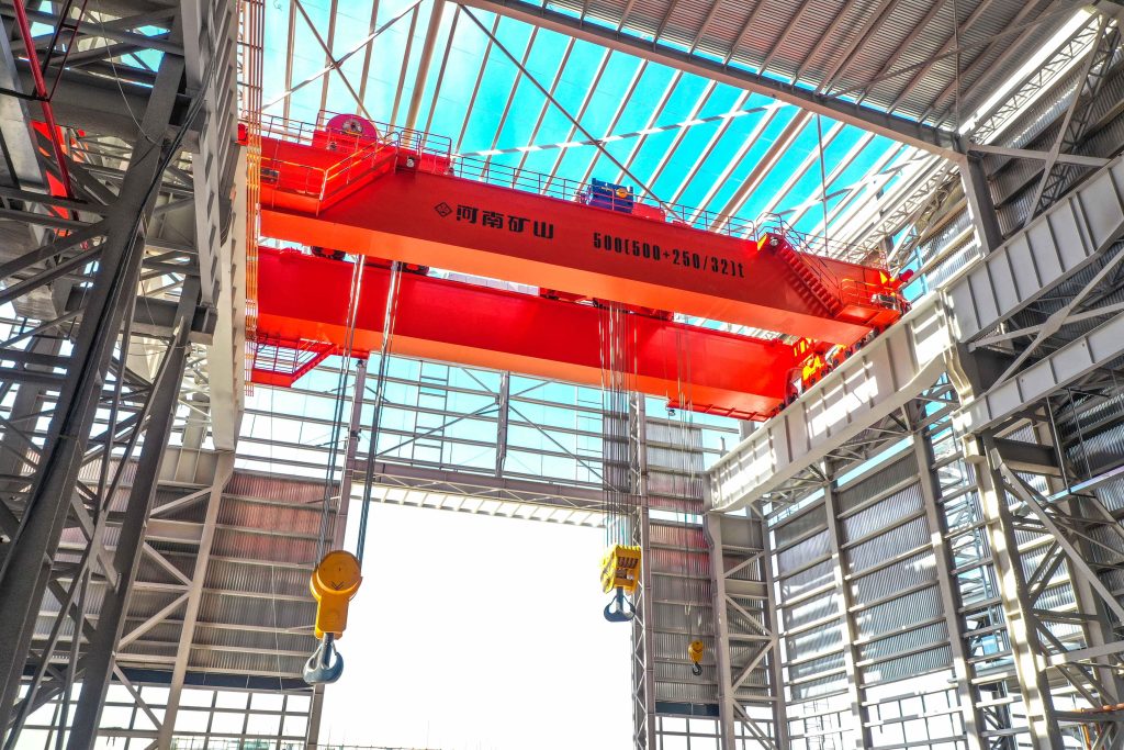
Controlled component transfer and positioning for precision assembly.
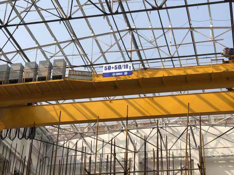
Heavy fabrication, production lifting and factory crane automation.
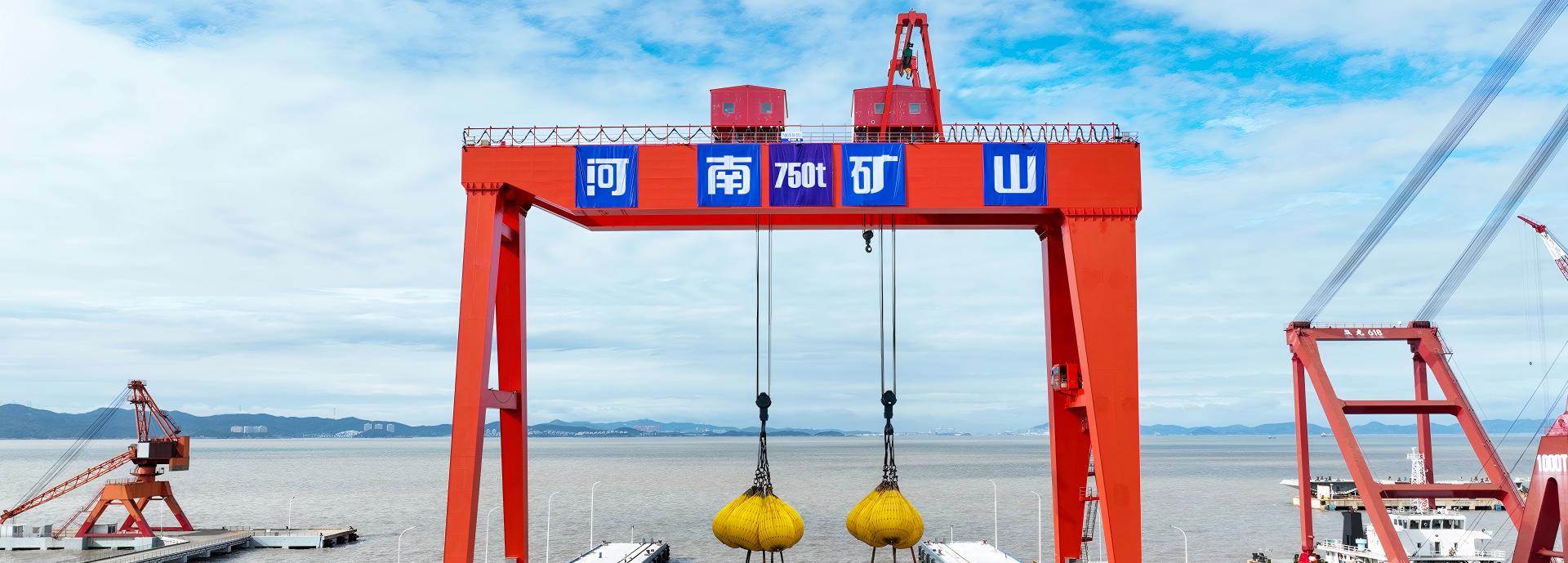
Process lifting for smelters, carbon blocks and anode materials.
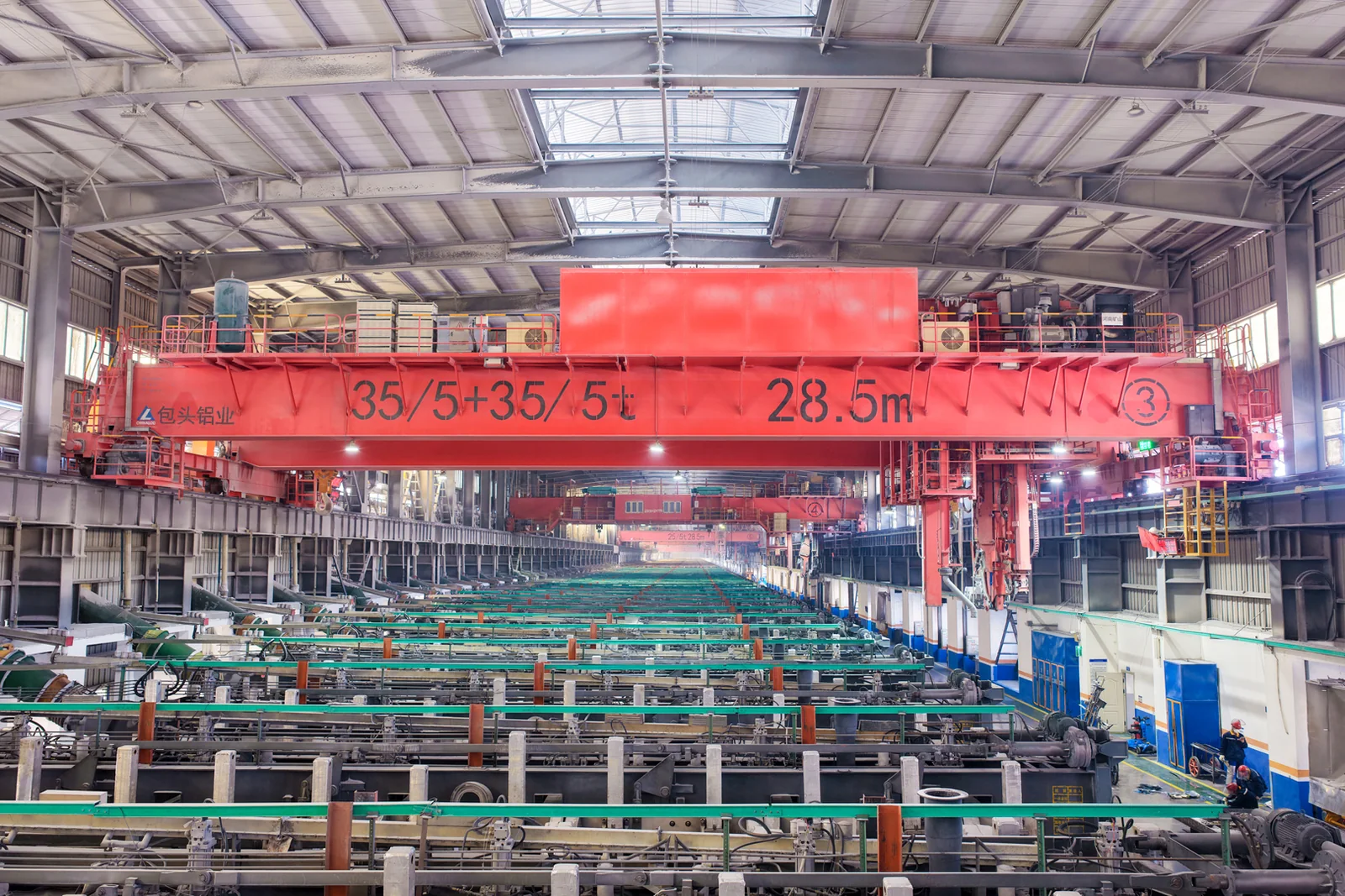
Clean lifting and classified protection for sensitive process areas.
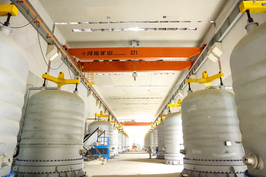
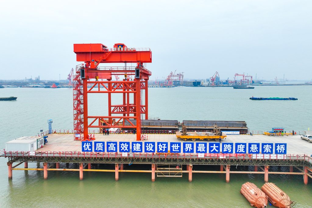
Bridge fabrication, metro construction and ship block assembly.
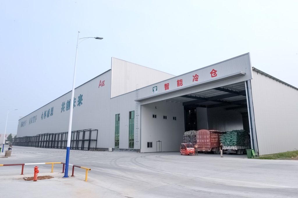
Automated storage and retrieval for plates, cables and bins.
Follow project dispatches, crane engineering and factory acceptance.
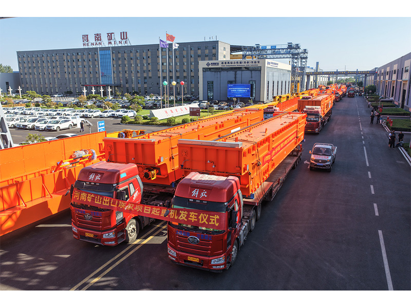
Dispatch, installation and equipment in service
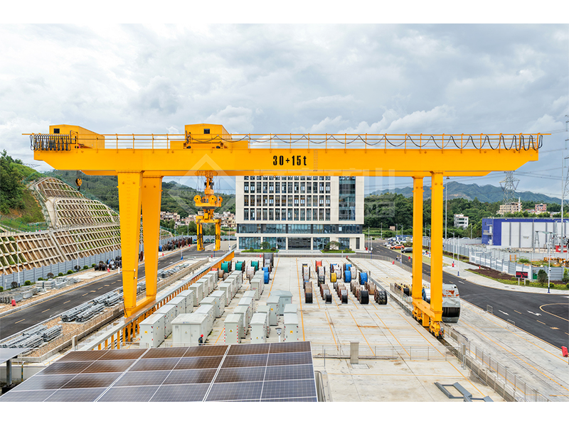
Crane configurations and handling technology
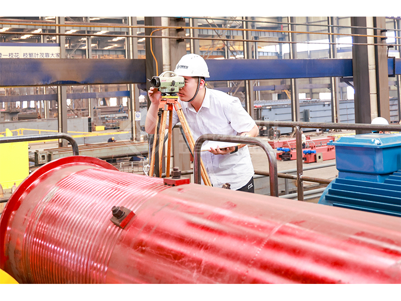
Factory inspections, acceptance and test programmes

Company developments, people and community programmes
Move components, machinery and packaged loads along a dedicated yard or workshop runway. The MH combines a single box girder with an electric wire-rope hoist. Compare the 3, 5, 10, 16 and 20 t configurations around your span, hook height and lifting cycle.
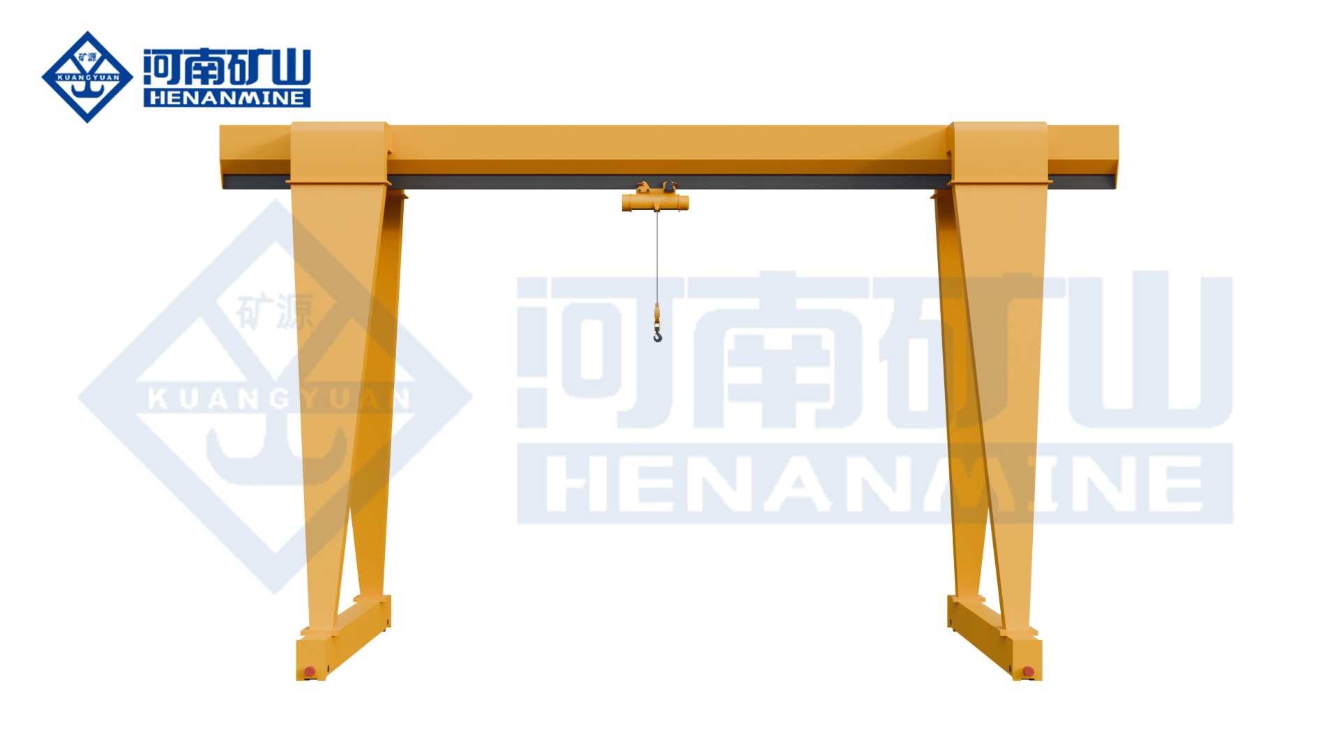
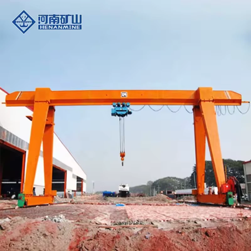
Move fabricated assemblies and machine parts between workstations. Check the highest pickup point and the room occupied by the hoist and rigging before fixing the crane height.
Serve defined storage and loading positions along a ground-rail route. Coordinate vehicle access, load passage between the legs and any lifting point outside the main span.
Provide a repeatable lifting point for equipment removal and replacement. Select the suspended load including lifting beams and slings, and compare single-speed with slower final-approach lifting.
Compare the lifting mechanism, control functions and site interfaces for the selected crane.
Select one matched MH box-girder configuration. Load, span, hoist type and power depend on the chosen row; the 20 t duty is selected with the HC package.
| Model | MH | Rated capacity | 3 / 5 / 10 / 16 / 20 t |
|---|---|---|---|
| Span options | 12 / 16 / 20 / 24 m; 30 m on 5–20 t configurations | Lifting height | 6 m or 9 m |
| Working class | A3 at 3–16 t; 20 t duty selected with the HC hoist package | Girder construction | Welded box girder / full gantry |
| Hoist type, 3–10 t | CD1 single-speed or MD1 dual-speed wire-rope hoist | Hoist type, 16 / 20 t | CD1 at 16 t; HC at 20 t |
| Hoisting speed, 3 / 5 t | 8 m/min or 8 / 0.8 m/min | Hoisting speed, 10 t | 7 m/min or 7 / 0.7 m/min |
| Hoisting speed, 16 / 20 t | 3.5 m/min | Hoist cross-travel speed | 20 m/min |
| Hoist motor, 3 / 5 t | 4.5 kW / 7.5 kW, single-speed hoist | Hoist motor, 10 / 16 / 20 t | 13 kW / 13 kW / 18.5 kW, single-speed hoist |
| Hoist-travel motors, 3 / 5 t | 0.4 kW / 0.8 kW | Hoist-travel motors, 10 / 16 / 20 t | 2 × 0.8 kW / 2 × 0.8 kW / 4 × 0.8 kW |
| Runway rails, 3 / 5 t | P24 or P38, selected with span and wheel reactions | Runway rails, 10 / 16 / 20 t | P38 or P43 at 10 / 16 t; P43 or P50 at 20 t |
| Power supply | 380 V, 50 Hz, 3-phase | Operating temperature | −20°C to +40°C for the specified equipment |
| Operating controls | Ground pendant / cabin; remote control by configuration | Cantilever arrangement | With or without cantilever; outside-span reach by design |
| Crane runway | Ground-level rails on both sides | Operating pattern | Intermittent, repeated material and component handling |
Swipe the table on a small screen to compare all columns.
| Capacity | Hoist | Lifting speed m/min | Single-speed lifting motor kW | Hoist-travel motors kW | Rail options |
|---|---|---|---|---|---|
| 3 t | CD1 / MD1 | 8 or 8 / 0.8 | 4.5 | 0.4 | P24 / P38 |
| 5 t | CD1 / MD1 | 8 or 8 / 0.8 | 7.5 | 0.8 | P24 / P38 |
| 10 t | CD1 / MD1 | 7 or 7 / 0.7 | 13 | 2 × 0.8 | P38 / P43 |
| 16 t | CD1 | 3.5 | 13 | 2 × 0.8 | P38 / P43 |
| 20 t | HC | 3.5 | 18.5 | 4 × 0.8 | P43 / P50 |
Motor figures refer to the shown single-speed arrangements. A dual-speed package has its own motor schedule. Rail profile, span, hook height and wheel reactions are confirmed for the selected crane.
Review the original equipment views alongside the selected crane drawing.

Select CD1 single-speed or MD1 normal-and-creep lifting for 3–10 t, CD1 for 16 t and HC for 20 t. Match the speed, motor and rail package to its capacity row; include rigging in the suspended load.
Define in-span and any cantilever positions, hook approaches, leg opening and the hoist envelope. Useful hook height and overall frame height are different dimensions; include the lifting beam, slings and landing clearance.
Choose pendant, cabin or remote control for the operator’s sightline. Coordinate rail centres, travel length, rail profile, wheel and horizontal reactions, foundations, power feed and both ground runways with vehicle and pedestrian routes.
Specify operating and parked wind, rain, temperature and corrosion exposure, parking and travel restraint. Plan hoist, wheel and drive inspection access; match maintenance instructions and spares to the supplied CD1, MD1 or HC equipment.
Start with one complete MH crane or state the number of units your project needs. The quotation confirms quantity, lifting equipment, controls, power feed and any rails or runway equipment included.
Capacity, dimensions, duty, selected components, packing, freight and installation services influence the quoted price.
Include the technical drawing, mechanism and electrical schedules, inspection or test records, operating instructions and destination requirements in the supply scope.
Any required certification, inspection standard or equipment protection must apply to the selected model and configuration.
The offer sets the manufacturing and delivery schedule after the equipment is agreed. Confirm packing, shipment, site lifting access, assembly and commissioning responsibilities.
Ask the written offer to state the warranty period, service arrangements and spare-parts scope for your crane.

Loading routes where side access matters
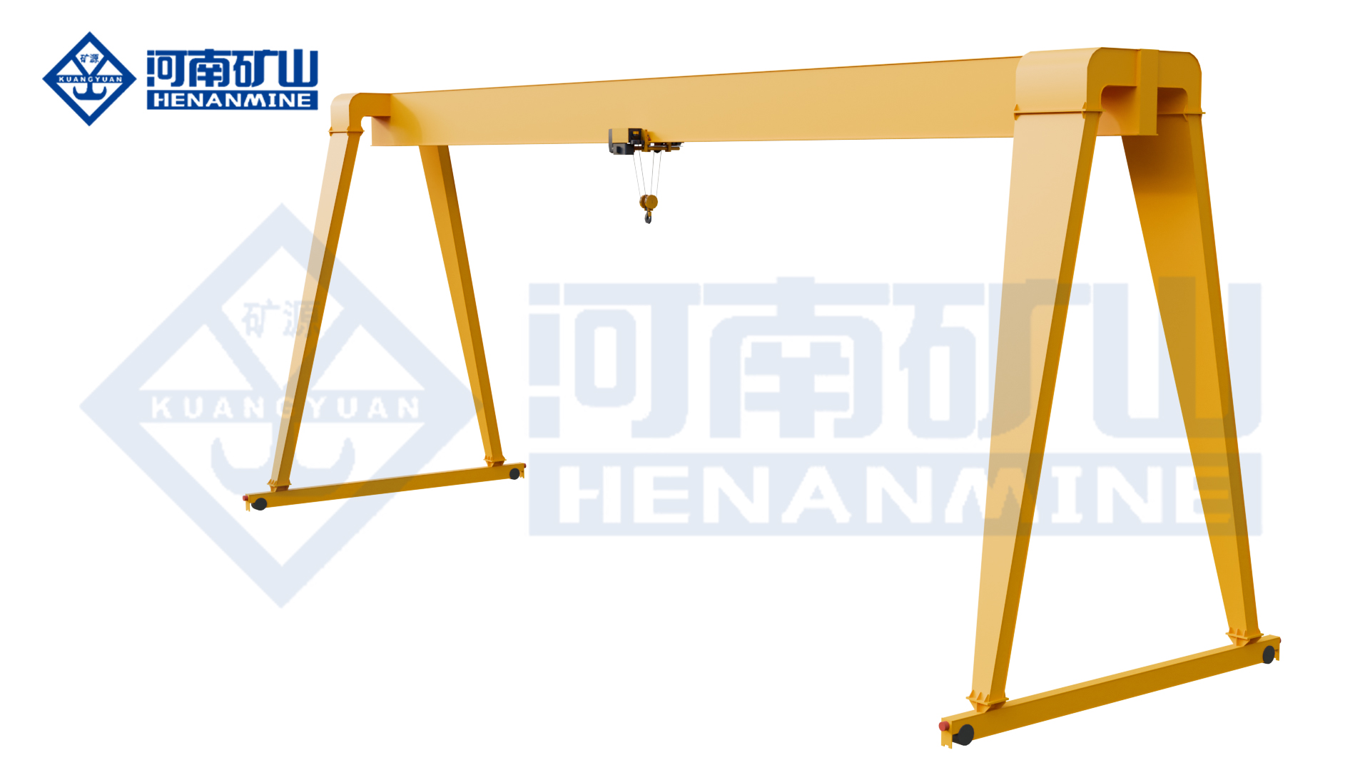
Workshop or yard handling with a new-design hoist package
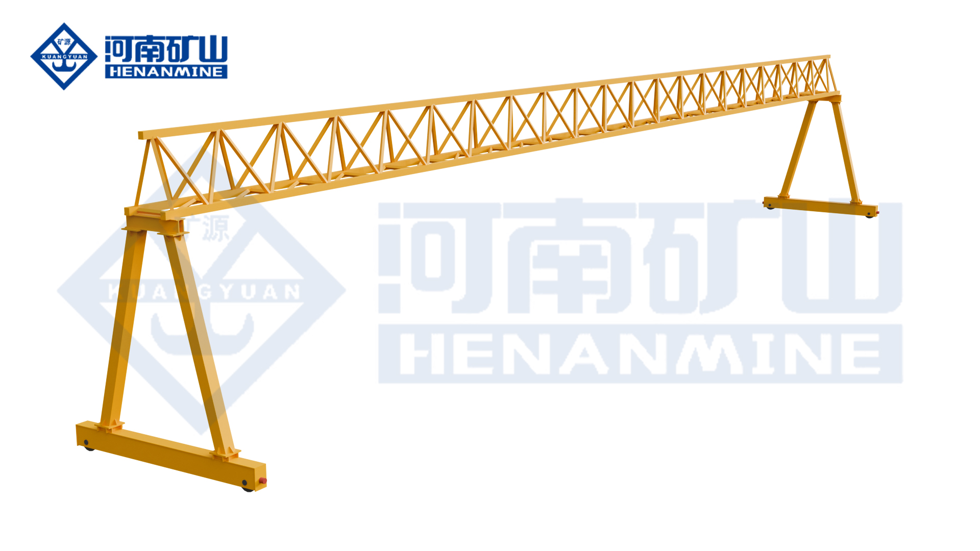
Outdoor rail routes comparing truss and box girders
Compare the handling task, selected lifting equipment and supply scope before ordering.
Start with the heaviest complete suspended load, including slings and any lifting beam. The configurations here cover 3, 5, 10, 16 and 20 t. Select the span, lifting height and duty with that load so the complete crane and its supporting runway can be assessed together.
No. The 3–10 t configurations offer CD1 or MD1 arrangements, while the shown 16 t and 20 t configurations use CD1 and HC respectively. The configuration table keeps capacity, hoist type, lifting speed and motor values together. A different mechanism package requires its own selection.
An agreed cantilever arrangement can provide outside-span lifting reach. The drawing must identify the required reach, load position, leg clearance and applicable load case. Include the outside-span pickup and set-down points when requesting the layout.
The listed P24, P38, P43 and P50 options apply to different capacity and span arrangements. Use the chosen crane's wheel geometry, reactions and runway design to select the final rail profile; the crane tonnage alone is not enough.
Send the load, approximate span, required hook height and destination. Add the main lifting task and any outside-span reach. A site sketch or photograph can establish the starting layout before a dimensioned technical offer is prepared.
Useful hook height describes the hook position needed for the work. The hoist, girder, slings and workpiece use part of the available space. Show the pickup and landing levels so the drawing can establish the upper hook position, approaches and overall structure together.
Include the vehicle positions, crossings and access routes in the layout. The moving legs, rails and suspended load occupy part of the working area. Planned loading and stopped positions help coordinate crane handling with vehicle and pedestrian activity.
Identify an accessible service position for the selected hoist and travel equipment, together with the isolation and access arrangements required by the site. The maintenance and spare-parts package should name the actual CD1, MD1 or HC equipment supplied.
Tell us what you lift, the approximate span, the required lifting height and your destination. If a dimension is unknown, describe the task and leave that field open.