
Choose the tipping edge
Use the same physical edge and moment reference for every input.
Bridge cranes for workshops and production lines.
Explore Overhead Cranes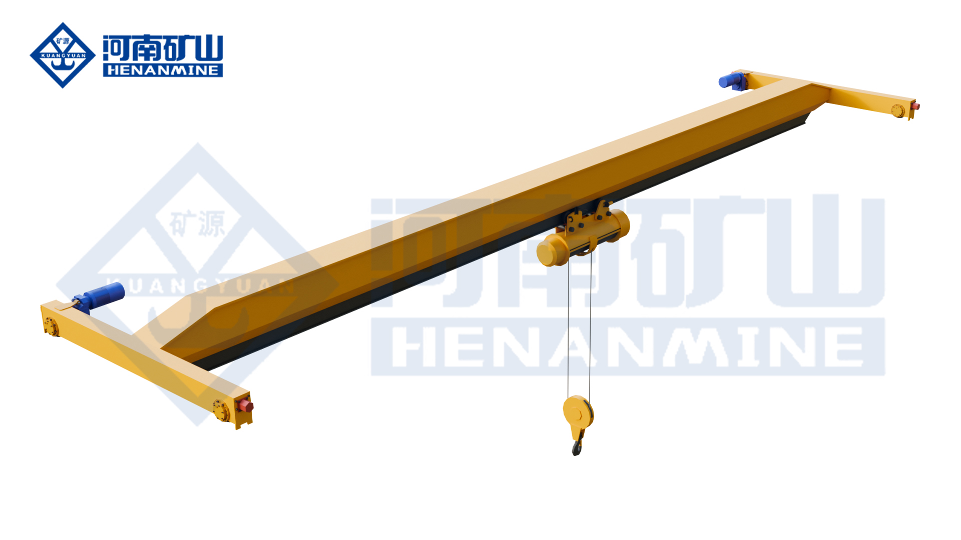
Ground-supported lifting for yards and construction.
Explore Gantry Cranes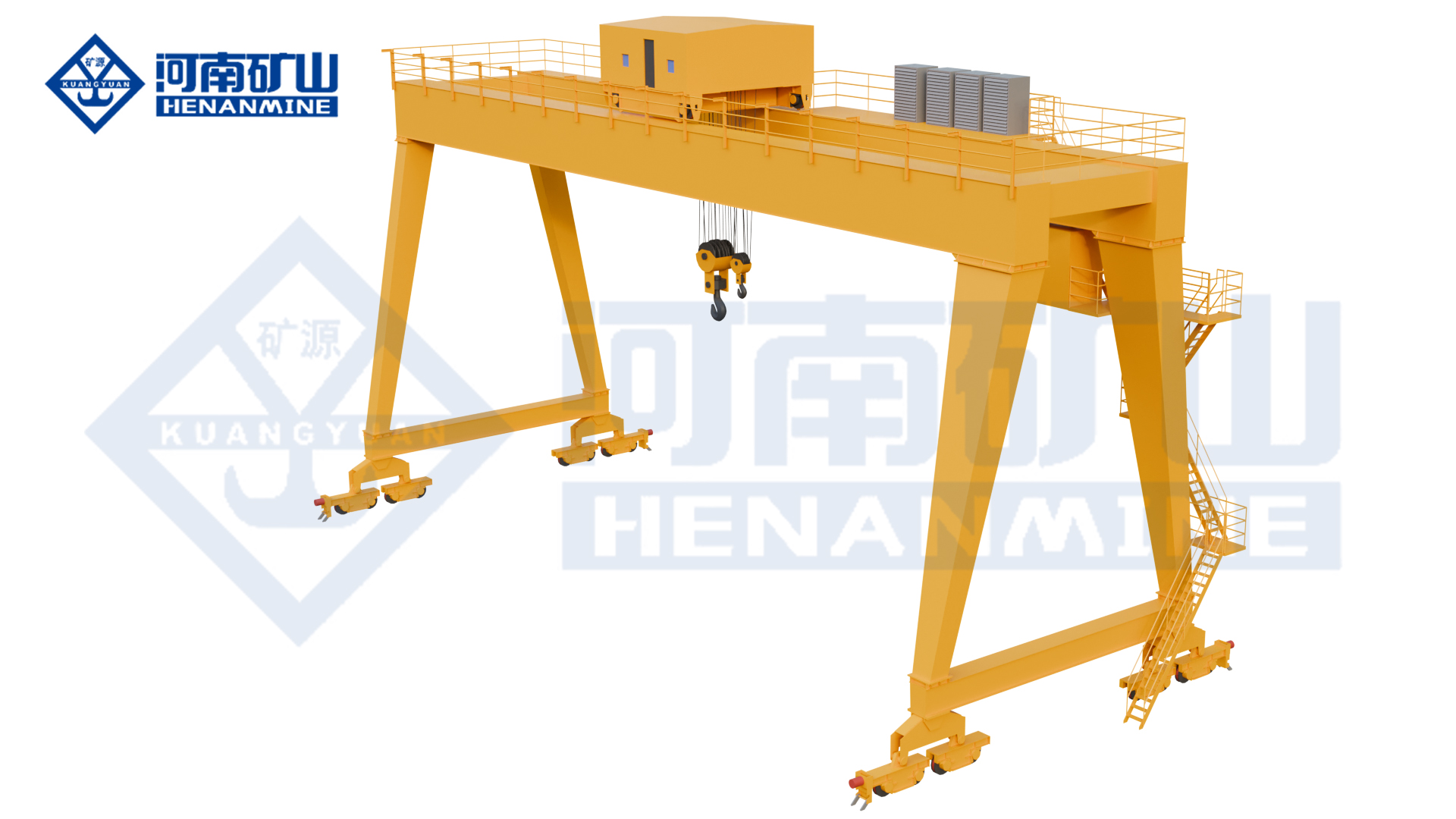
Wire rope and chain hoists for lifting points and cranes.
Explore Electric Hoists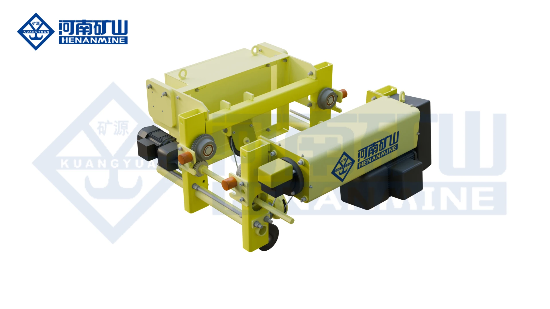
Wire rope lifting and pulling with a powered drum.
Explore Electric Winches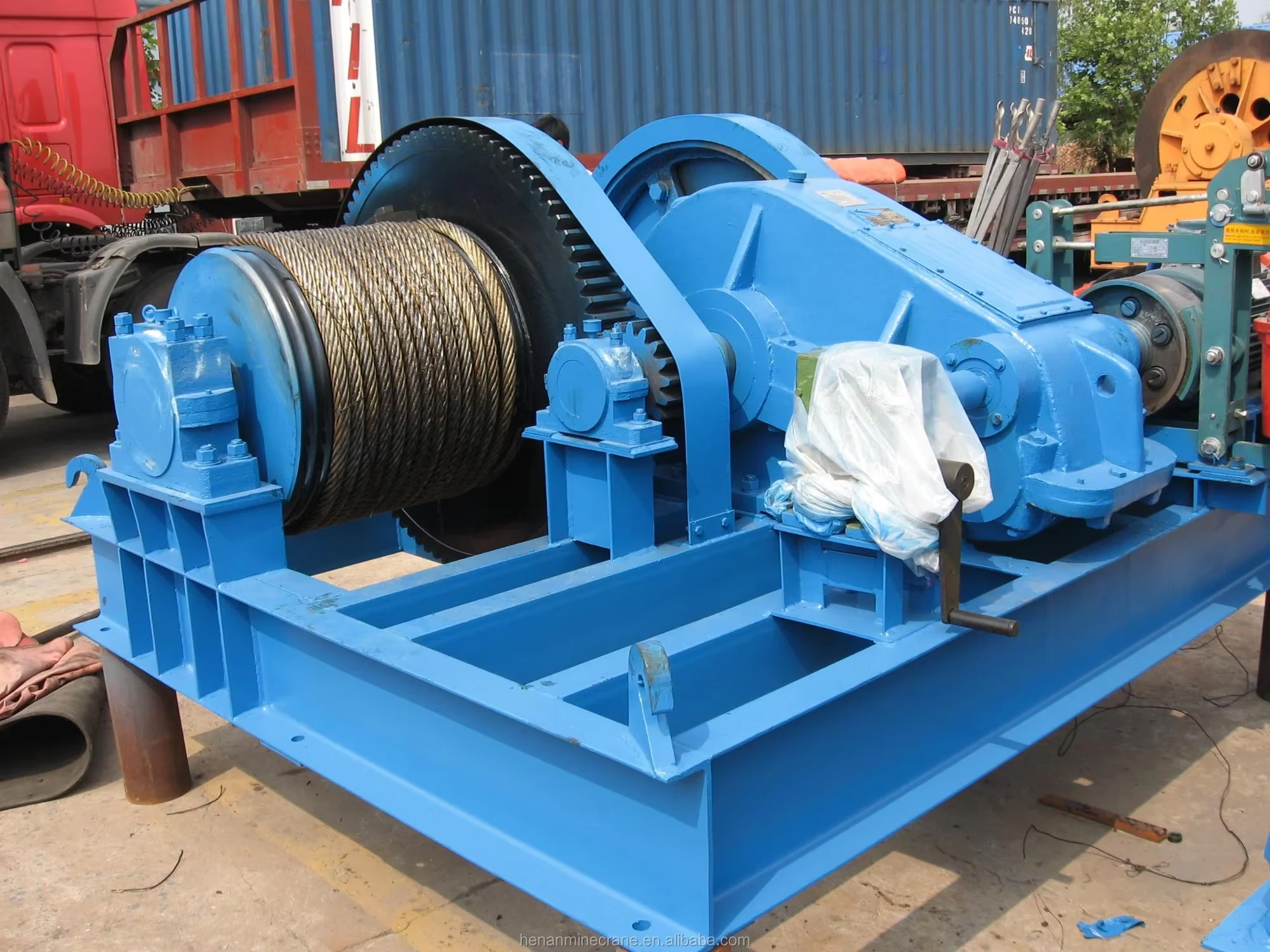
Grab buckets, magnets and hooks for your load.
Explore Lifting Attachments & Grabs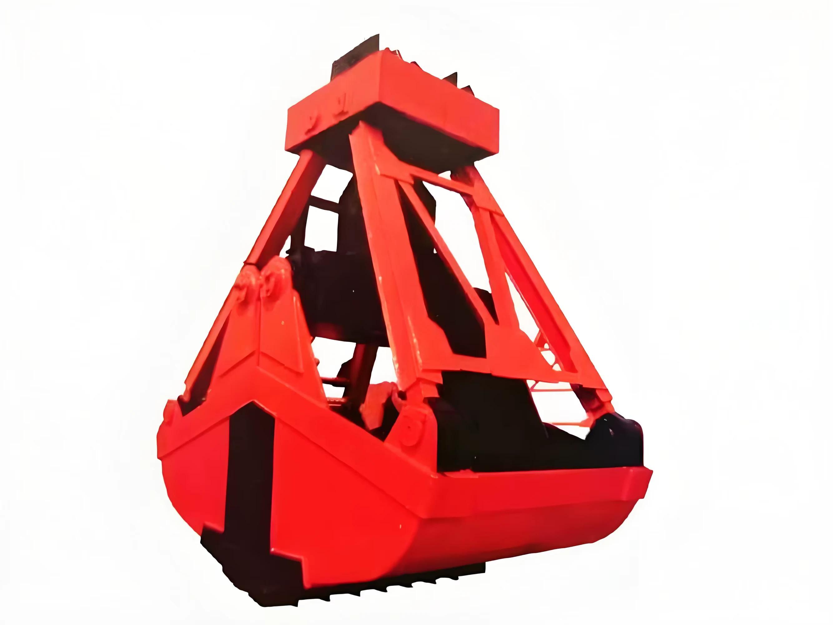
Mobile handling for containers, precast and yard loads.
Explore Rubber-Tired Gantry Cranes & Straddle Carriers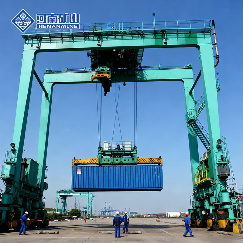
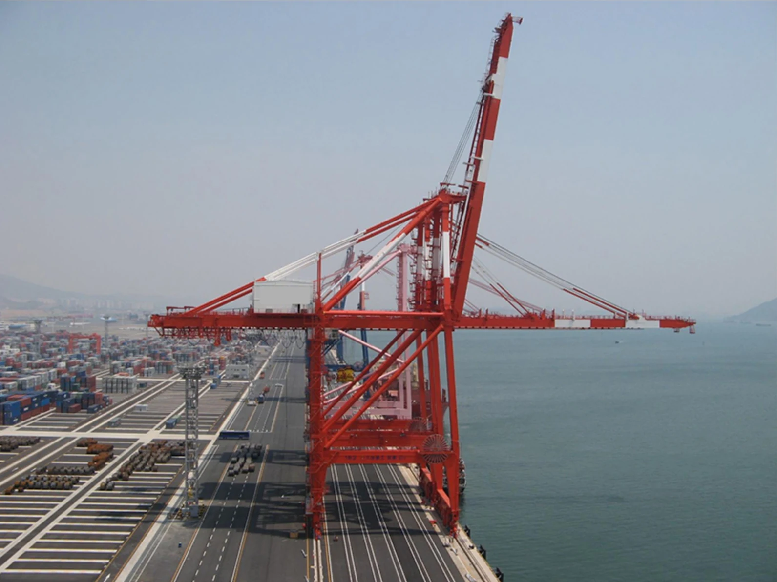
Lift and move vessels through boatyards and marinas.
Explore Marine Travel Lifts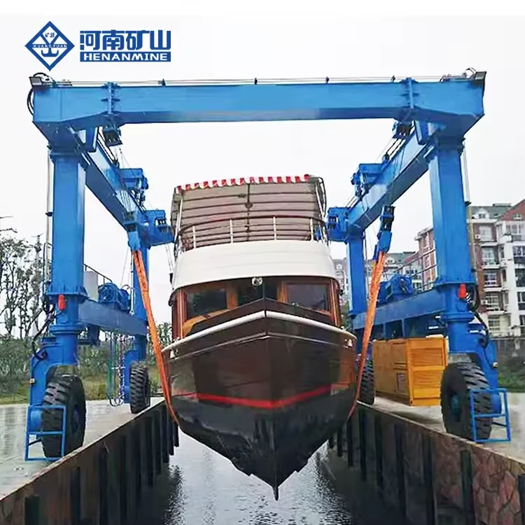
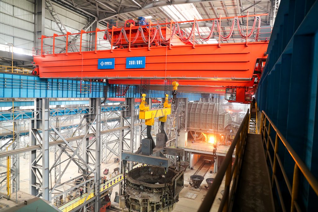
Ladle, slab, scrap and coil handling across steel production.
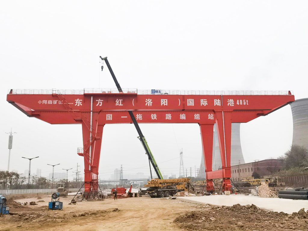
Container stacking and cargo transfers across terminals and rail.
Turbine installation, powerhouse maintenance and wind equipment assembly.
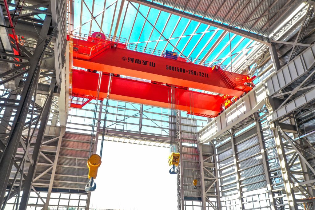
Controlled component transfer and positioning for precision assembly.
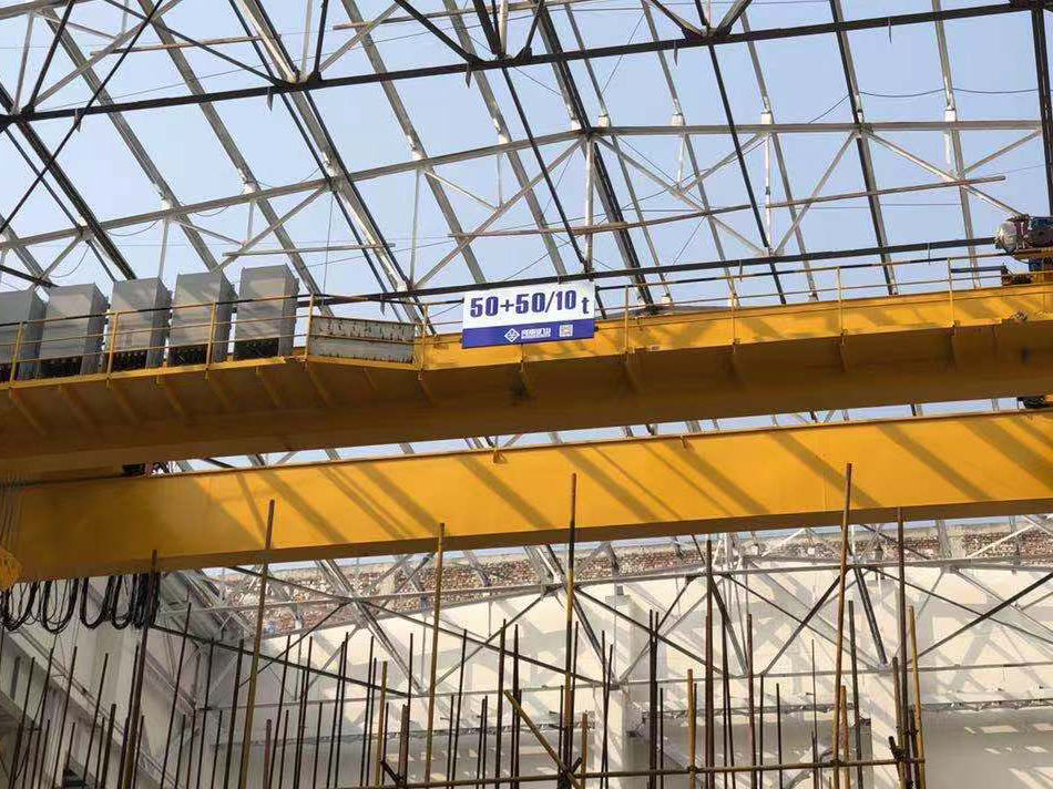
Heavy fabrication, production lifting and factory crane automation.
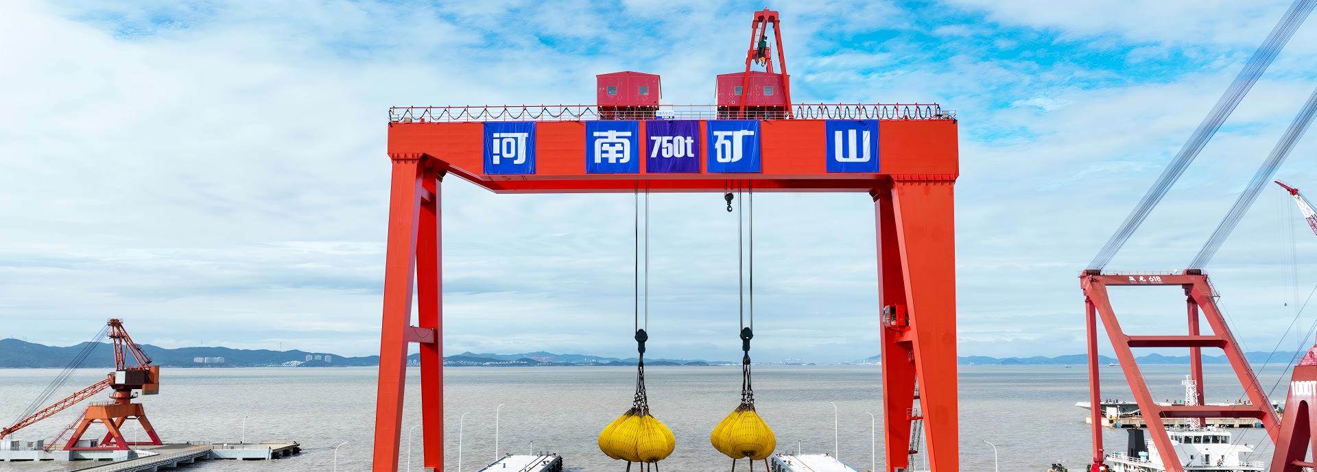
Process lifting for smelters, carbon blocks and anode materials.
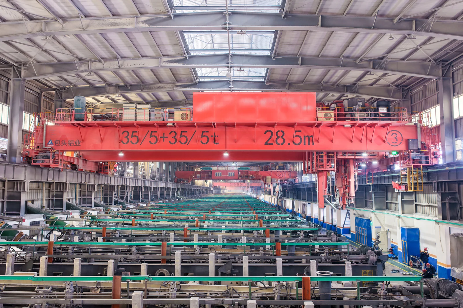
Clean lifting and classified protection for sensitive process areas.
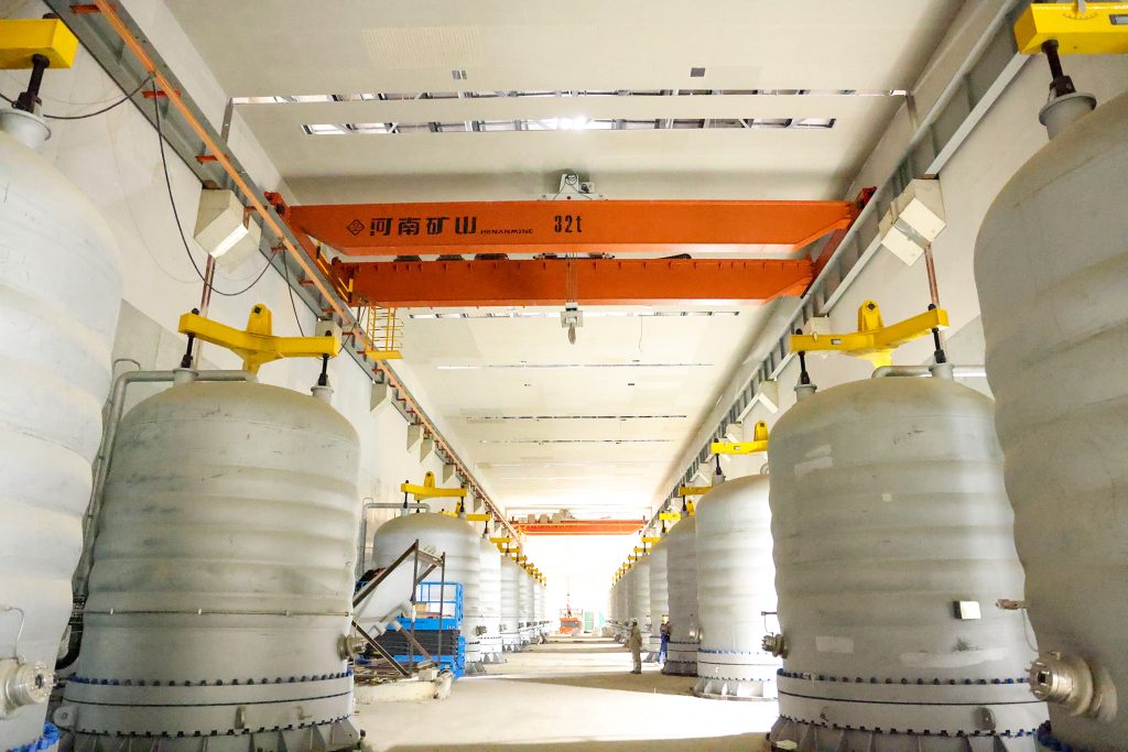
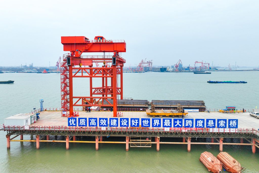
Bridge fabrication, metro construction and ship block assembly.
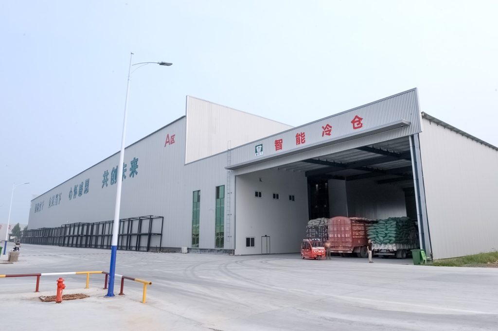
Automated storage and retrieval for plates, cables and bins.
Follow project dispatches, crane engineering and factory acceptance.
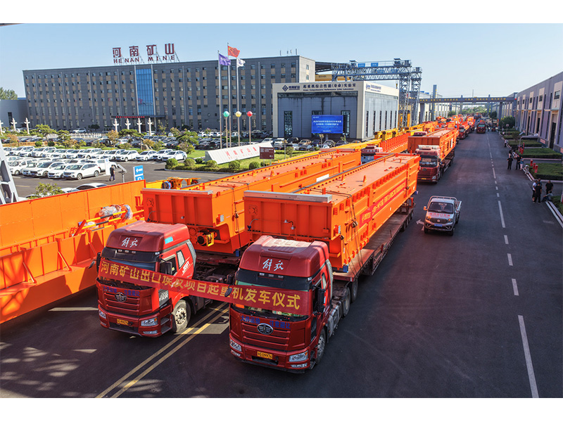
Dispatch, installation and equipment in service
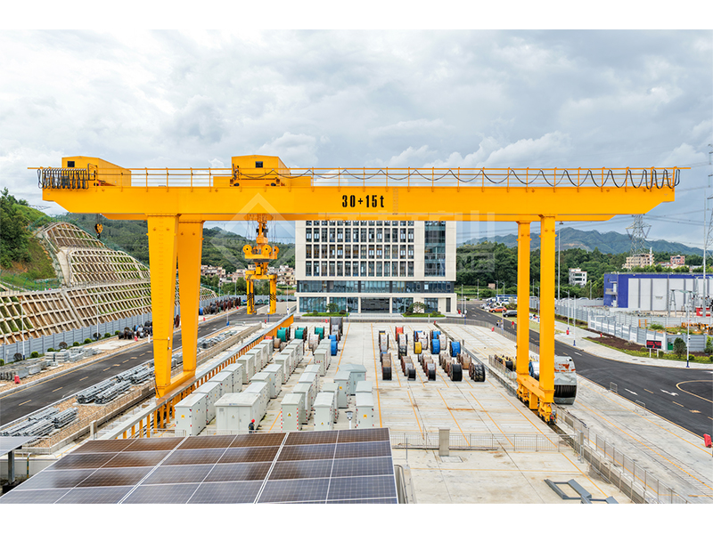
Crane configurations and handling technology
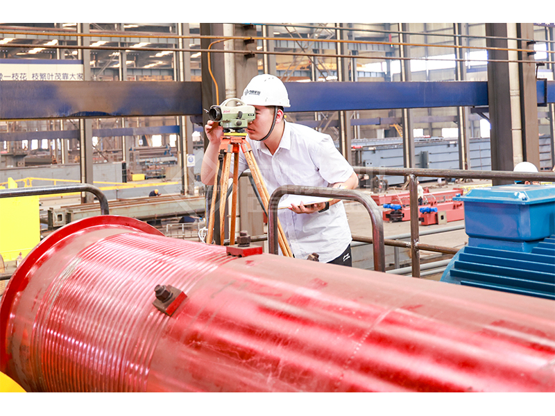
Factory inspections, acceptance and test programmes

Company developments, people and community programmes
Organize restoring and overturning actions about one selected tipping edge in a gantry assessment.
Use the same physical edge and moment reference for every input.
Put masses on the restoring side in the restoring term. Put masses outside the edge and destabilizing horizontal actions in the overturning terms.
Read the restoring moment, overturning moment and their ratio. Repeat for other edges and required load cases.
60,000 kg restoring mass at 4 m, 35 kN horizontal action at 12 m, and 5,000 kg outside the edge at 2 m; no other moment.
Restoring moment is 2,353.596 kN·m and overturning moment is 518.067 kN·m. The arithmetic moment ratio is about 4.543.
The ratio compares only the actions entered for this one edge and load case.
An algebraic balance above zero means the entered restoring moment exceeds the entered overturning moment; it is not a design acceptance.
Dynamics, acceleration, wind combinations, clamps, anchorage and uplift resistance require the appropriate separate model.
Measuring the restoring arm from the gantry centre while measuring the horizontal force height from the rail, so the moments do not share one reference.
M_restoring = m_restoring × g × arm / 1,000
M_overturning = F_horizontal × height + m_outside × g × arm_outside / 1,000 + M_other
Moment ratio = M_restoring / M_overturning
Acceptance depends on the applicable design method, factored load combinations and restraint arrangement. This tool deliberately assigns no universal threshold.
The tool reports “No overturning action” instead of an infinite ratio. That statement applies only to the entered case.