
Hoist, attachment and duty
Choose the electric-hoist trolley, hook or selected material attachment for complete suspended load, useful hook travel and placement. Match A3–A5 duty to load spectrum, handling frequency and attachment changes.
Bridge cranes for workshops and production lines.
Explore Overhead Cranes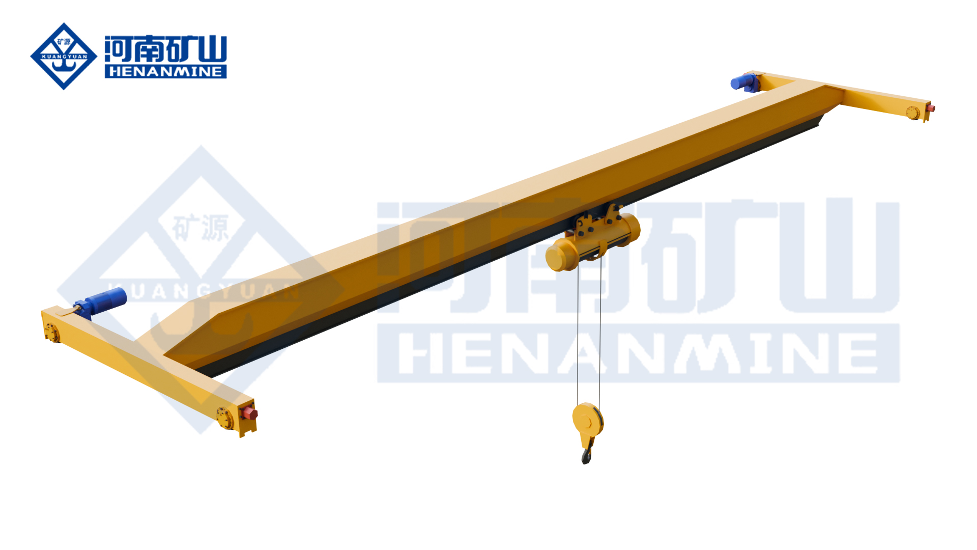
Ground-supported lifting for yards and construction.
Explore Gantry Cranes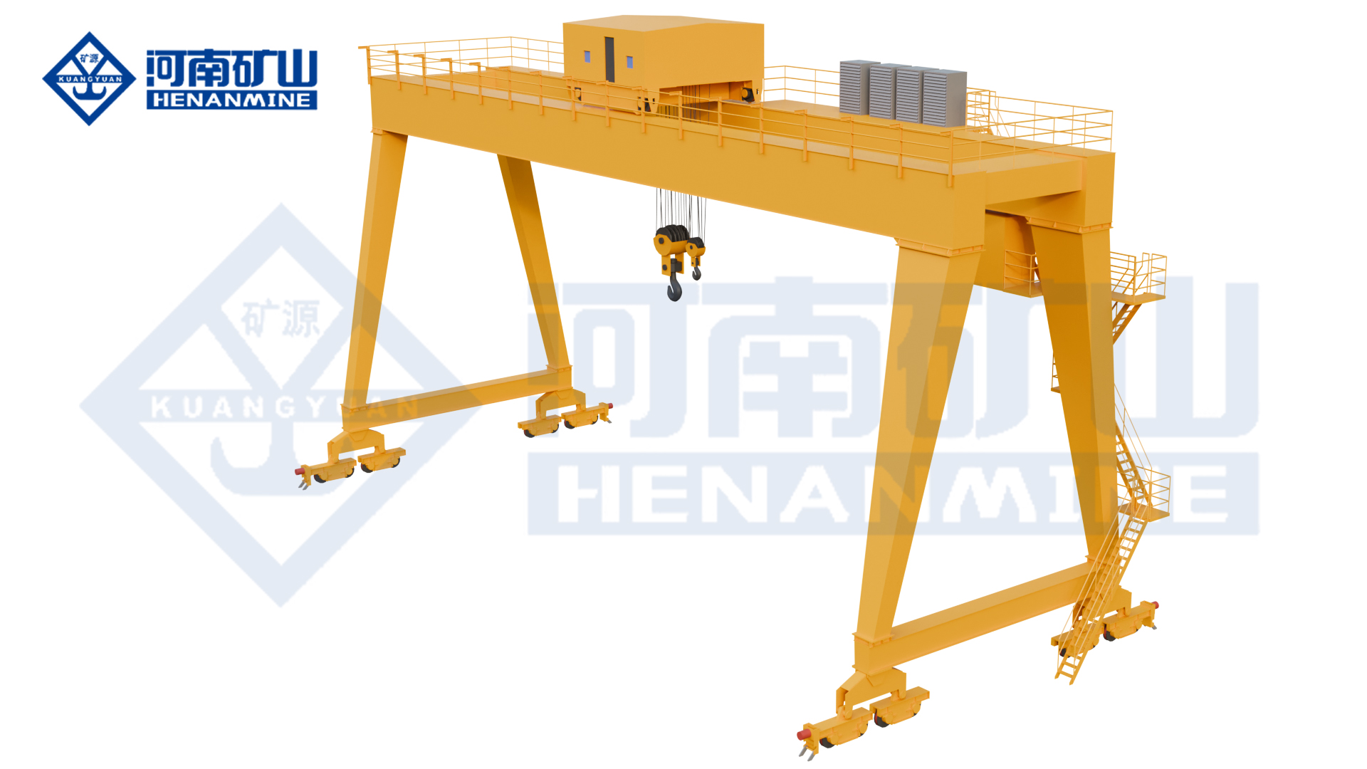
Wire rope and chain hoists for lifting points and cranes.
Explore Electric Hoists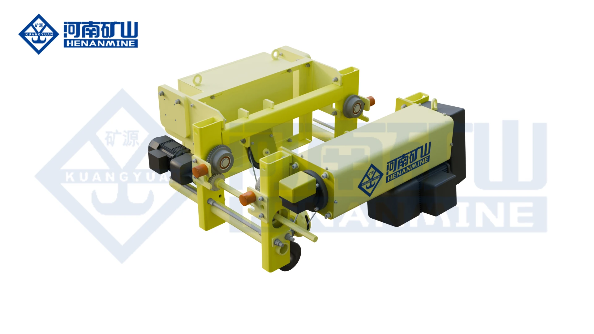
Wire rope lifting and pulling with a powered drum.
Explore Electric Winches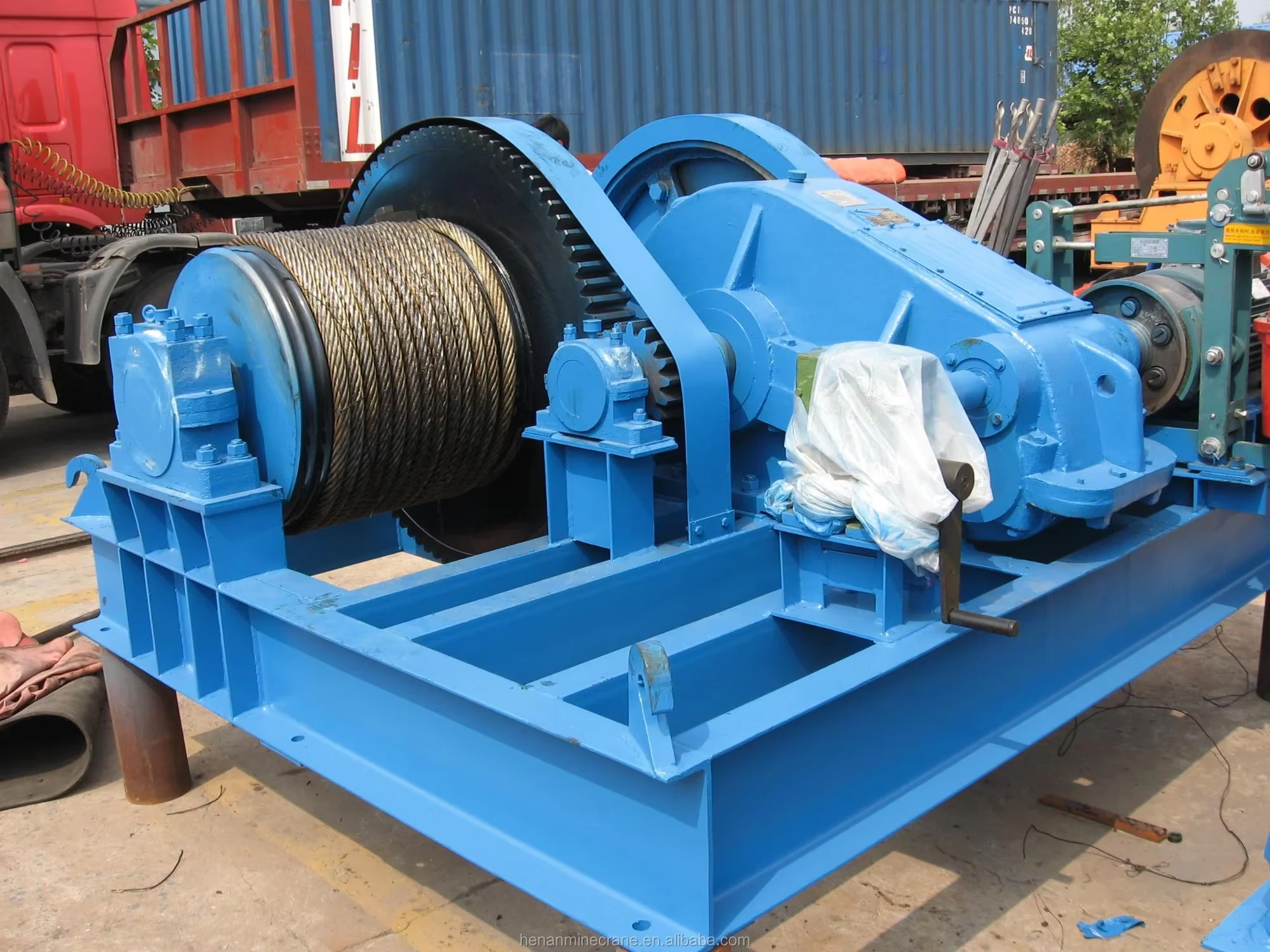
Grab buckets, magnets and hooks for your load.
Explore Lifting Attachments & Grabs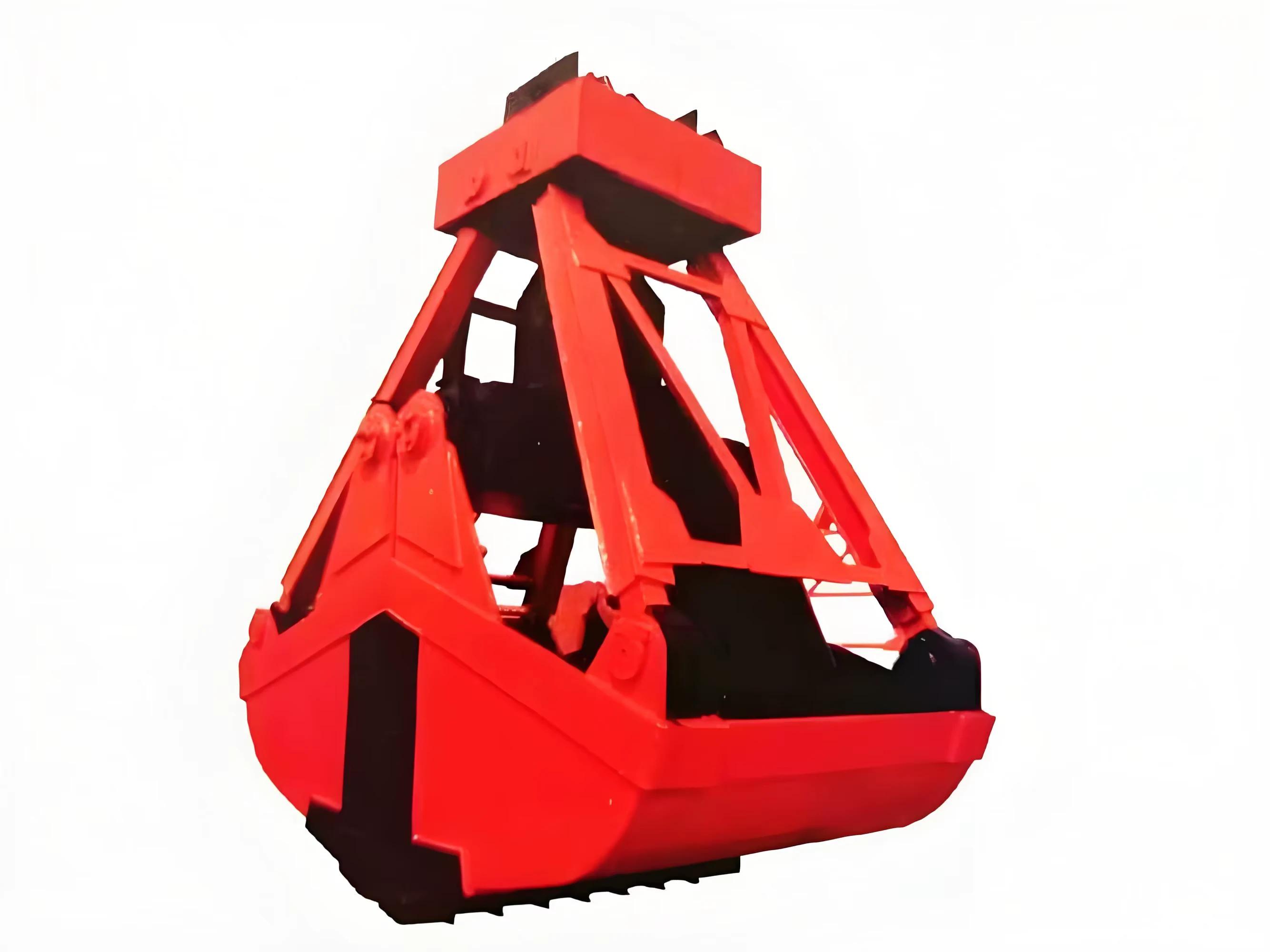
Mobile handling for containers, precast and yard loads.
Explore Rubber-Tired Gantry Cranes & Straddle Carriers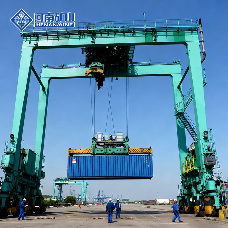
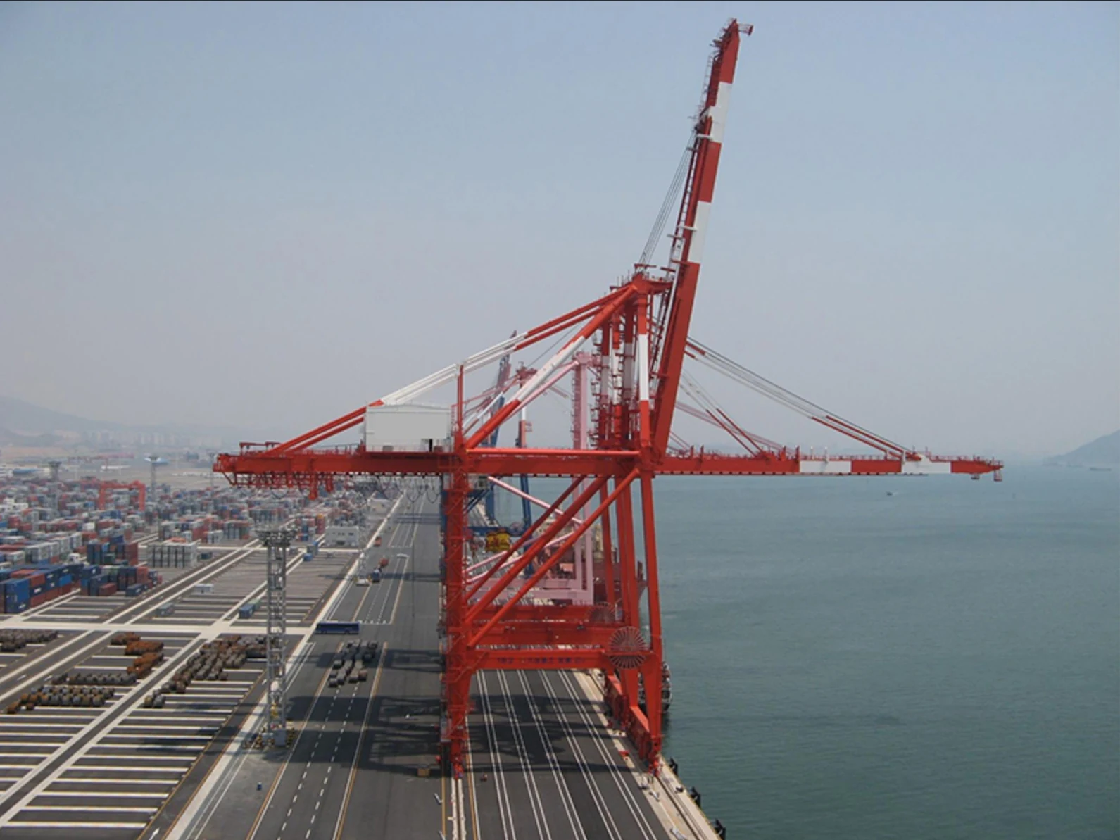
Lift and move vessels through boatyards and marinas.
Explore Marine Travel Lifts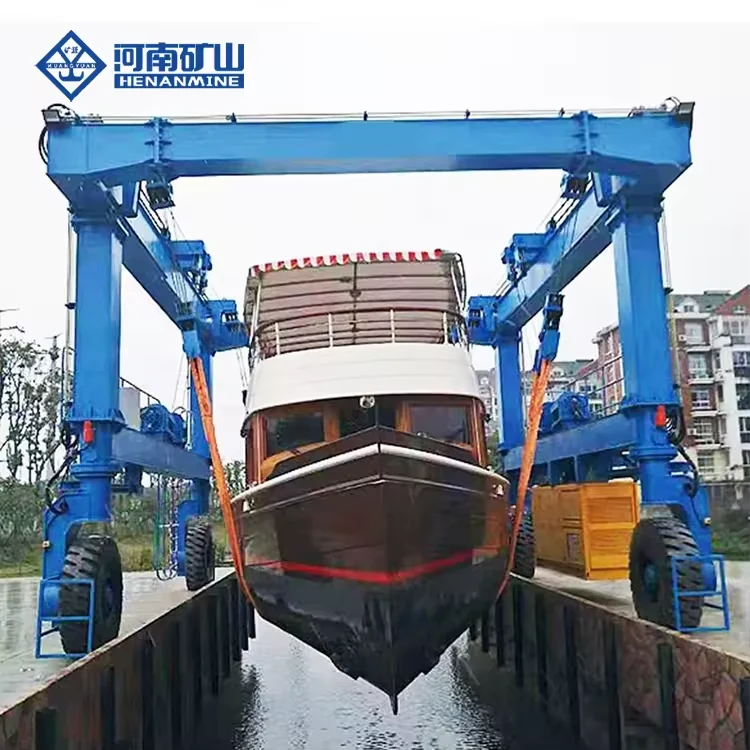
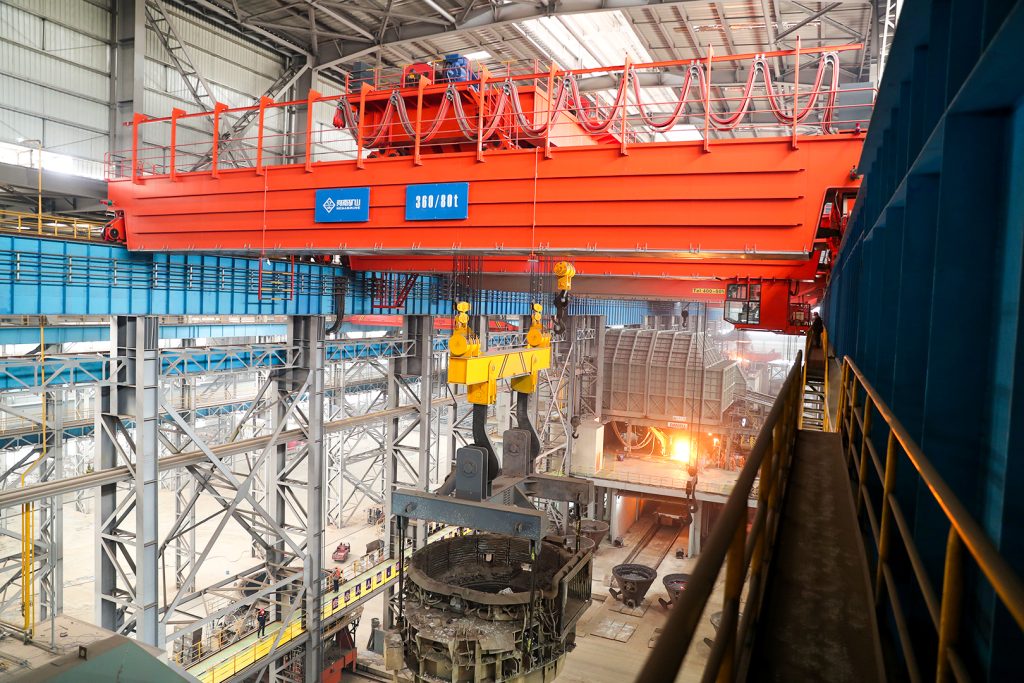
Ladle, slab, scrap and coil handling across steel production.
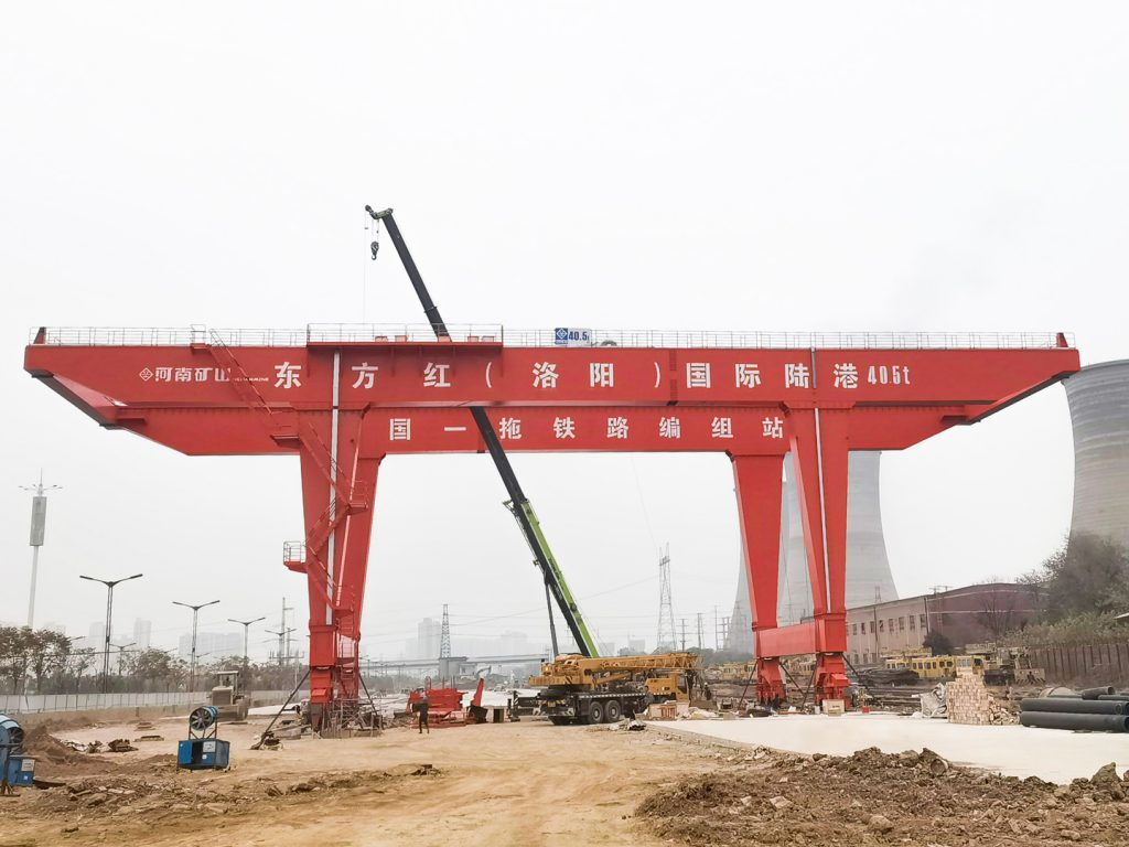
Container stacking and cargo transfers across terminals and rail.
Turbine installation, powerhouse maintenance and wind equipment assembly.
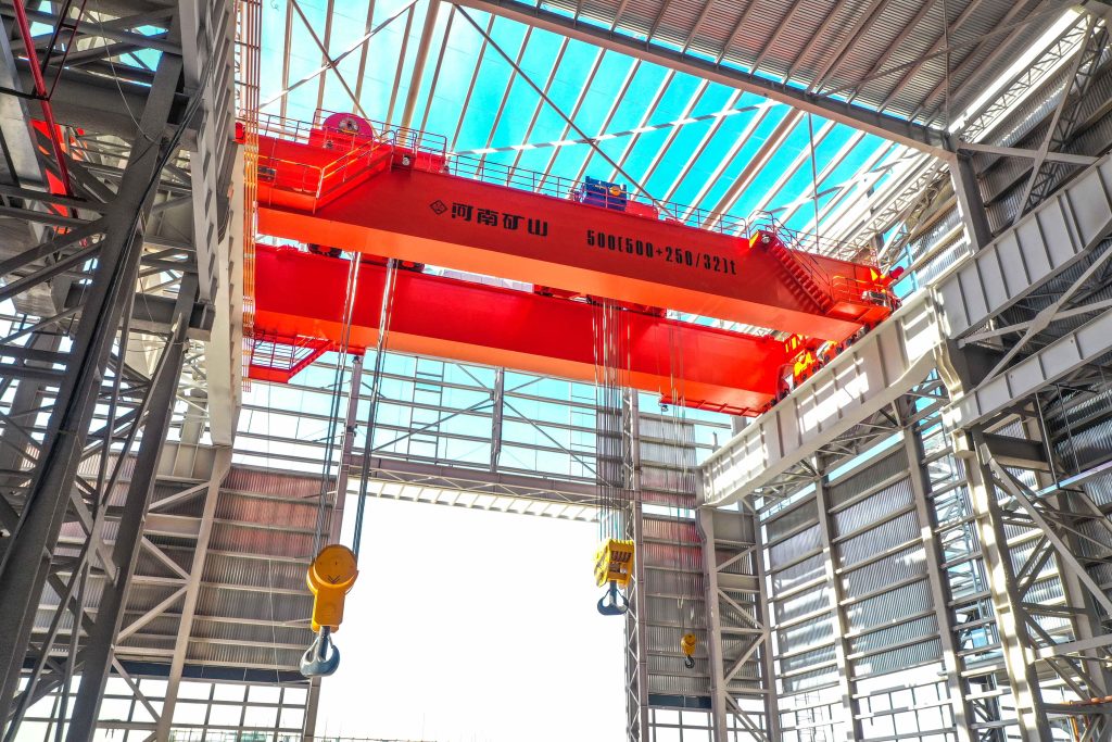
Controlled component transfer and positioning for precision assembly.
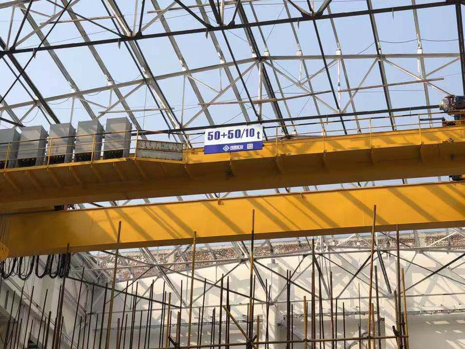
Heavy fabrication, production lifting and factory crane automation.
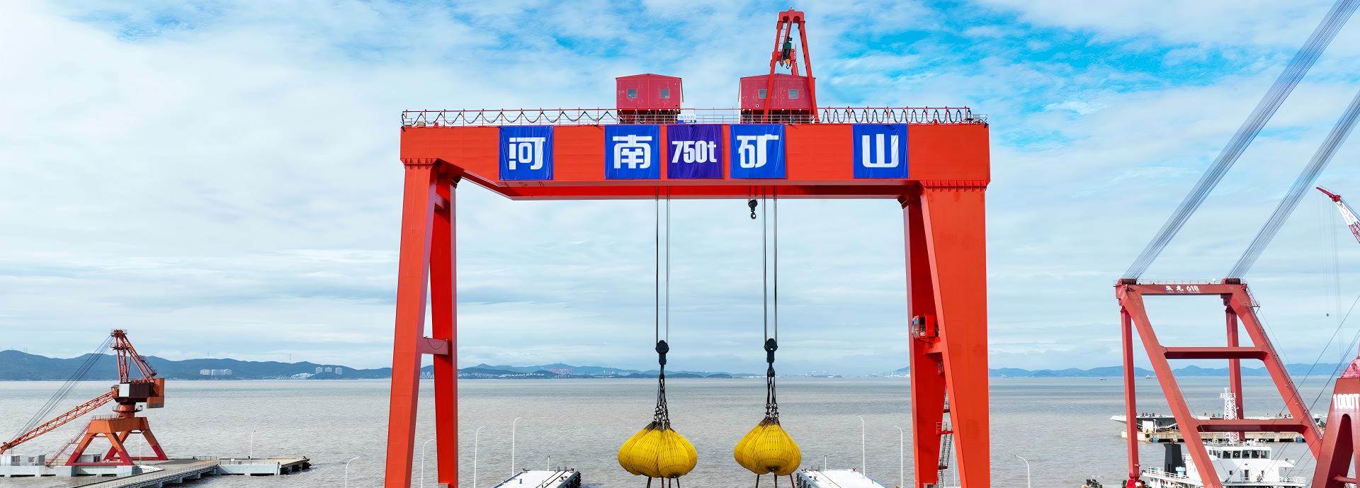
Process lifting for smelters, carbon blocks and anode materials.
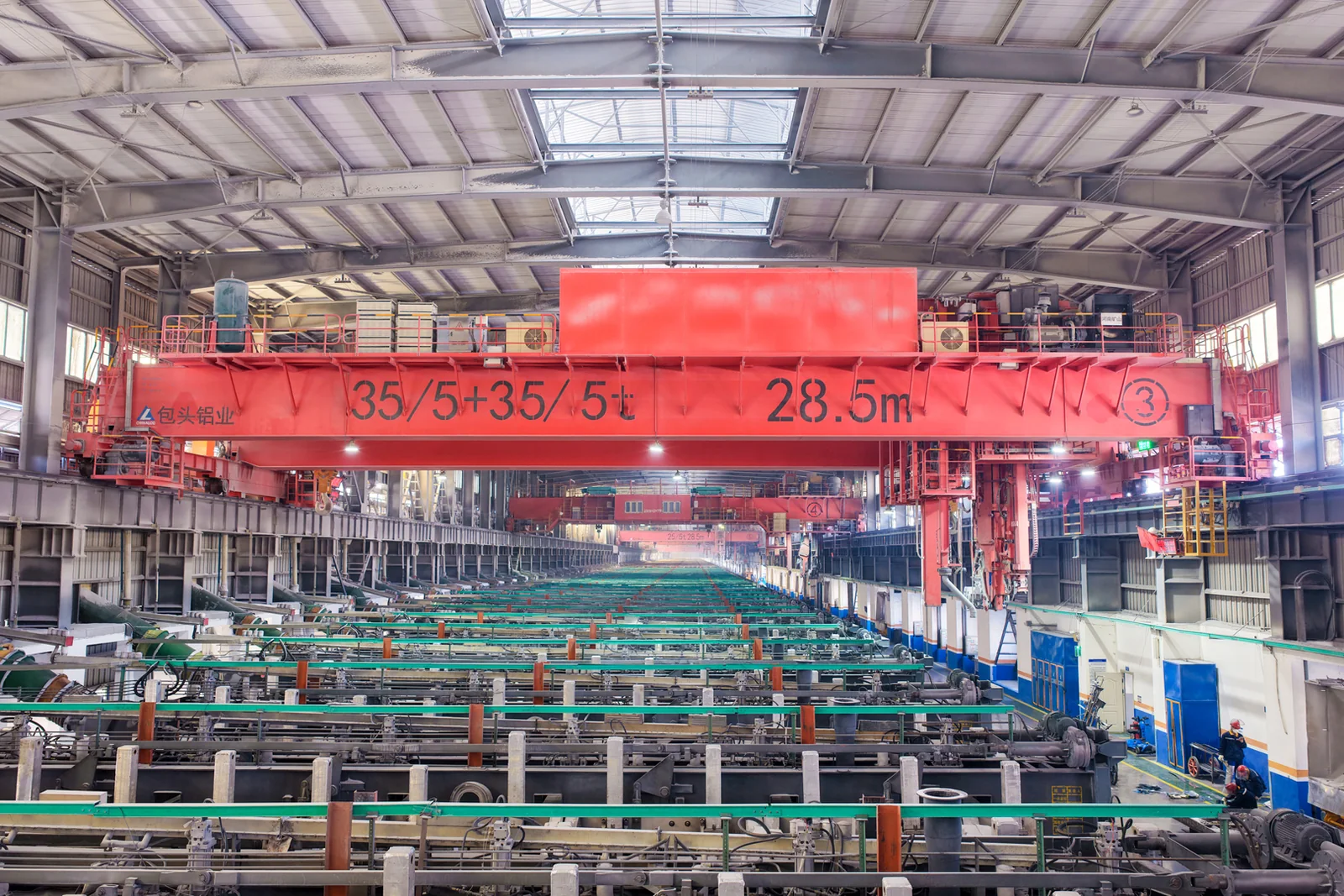
Clean lifting and classified protection for sensitive process areas.
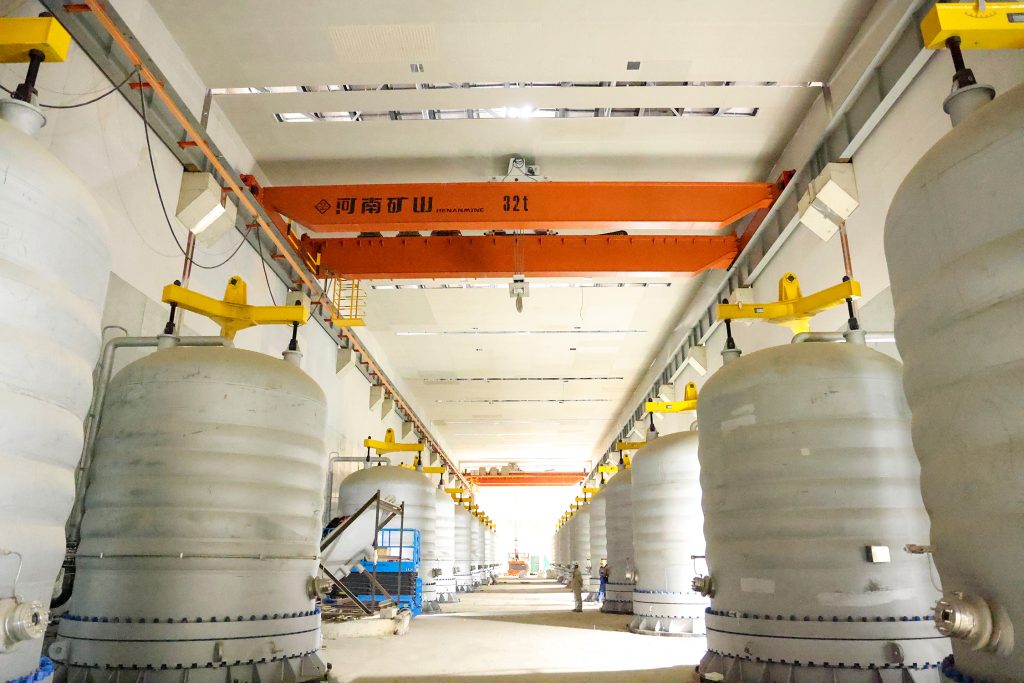
Bridge fabrication, metro construction and ship block assembly.
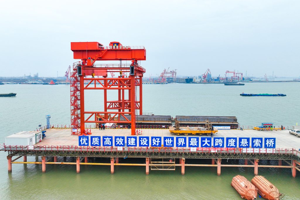
Automated storage and retrieval for plates, cables and bins.
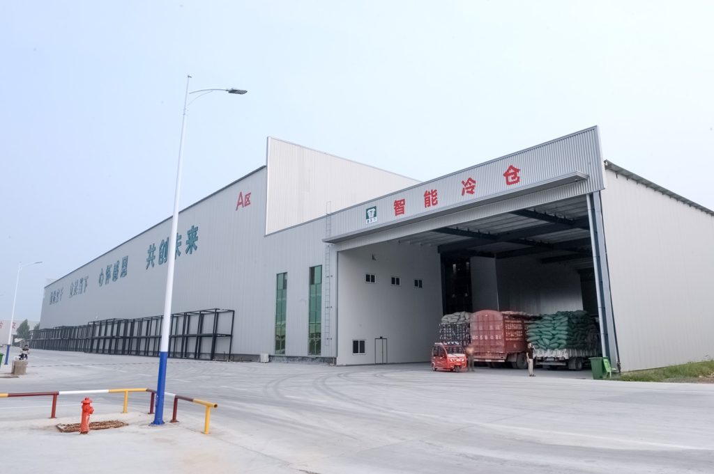
Follow project dispatches, crane engineering and factory acceptance.
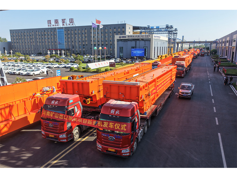
Dispatch, installation and equipment in service
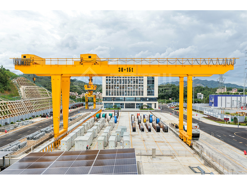
Crane configurations and handling technology
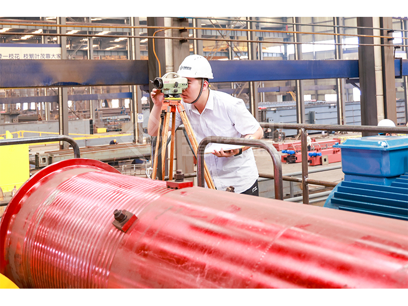
Factory inspections, acceptance and test programmes

Company developments, people and community programmes
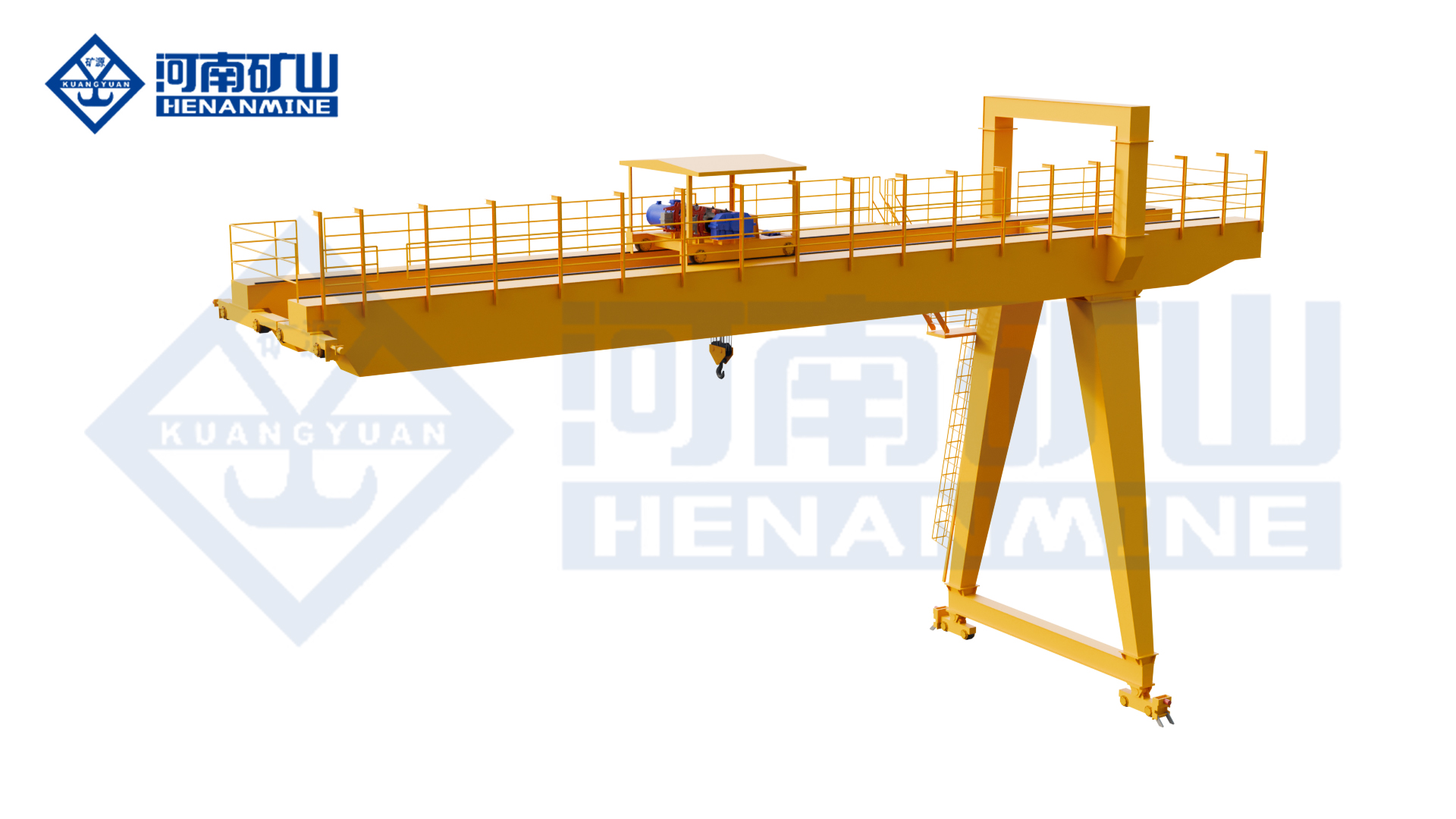
MB₁ provides double-girder electric-hoist handling along a workshop or storage edge. One end follows an elevated runway; the opposite leg runs on a ground rail. Select the hoist, direct-connected travel drives and controls with both support reactions, useful hook coverage and the floor corridor.

Serve fabrication fixtures and equipment positions along a building-side runway. The hoist trolley moves loads across the strip, while long travel connects workstations arranged along the same workshop edge.
Move rigged components between storage positions and a nearby loading lane. The semi-gantry route can follow the edge of the area, with vehicle access and the ground rail planned together.
Handle fixtures, assemblies and maintenance items along a production support zone. The compact travel drives and selectable controls help the crane fit a defined route beside other workshop activities.
Compare the lifting mechanism, control functions and site interfaces for the selected crane.
Select the complete electric-hoist package with both runway levels, hook clearance and supporting reactions. The A3–A5 range requires a class selected for the actual operating cycle.
| Model | MB₁ | Rated lifting capacity | Selected for the complete suspended load, including rigging |
|---|---|---|---|
| Span | Rail-centre span selected for the working area | Lifting height | Hook travel and headroom selected for pickup / set-down levels |
| Girder arrangement | Double girder | Runway/support layout | Semi-gantry; one elevated runway and one ground rail |
| Lifting mechanism | Electric hoist | Hoist/trolley arrangement | Electric-hoist trolley on twin girders |
| Lifting attachment | Hook / grab / electromagnetic lifting configurations | Working class | A3–A5 |
| Lifting speed | Lifting and positioning speeds matched to the selected electric hoist | Trolley travel speed | Cross-travel speed and stopping control selected for the load route |
| Crane travel speed | Long-travel speed selected for the runway and operating cycle | Travel drive / motion control | Three-in-one direct-connected crane and trolley travel drives |
| Operating controls | Pendant / wireless remote; cabin or PLC-linked control by configuration | Cantilever arrangement | With or without cantilever |
| Electrical supply | Site voltage, phases, frequency and power feed matched in the electrical package | Electrical protection | Cabinet, motor and connector protection selected for the environment |
| Runway rail profile | Rail section matched to wheel geometry, reactions and supporting structure | Motor ratings | Lifting, trolley and crane-travel motor ratings specified in the equipment schedule |
| Operating pattern | Intermittent, repeated loading/unloading and material handling | Site layout | Overall height, leg clearance and hook approach shown in the crane drawing |
Review the original equipment views alongside the selected crane drawing.

Choose the electric-hoist trolley, hook or selected material attachment for complete suspended load, useful hook travel and placement. Match A3–A5 duty to load spectrum, handling frequency and attachment changes.
One end follows an elevated runway and the opposite leg a ground rail. Check horizontal rail-centre span, both elevations, upper and lower hook positions, approaches and load clearance; assess building-side or independent supports using selected vertical and horizontal reactions.
Crane and trolley use three-in-one direct-connected travel drives. Select pendant, wireless remote, cabin or PLC-linked operation for visibility and the handling sequence. Coordinate the electrical supply and service access with both supporting sides.
Define any cantilever pickup point and its permitted load. Keep the ground-side leg corridor, vehicle crossings, walking routes, stopping positions and maintenance access clear throughout travel; include nearby production equipment and overhead obstructions in the layout.
Enquire for one complete crane or your project quantity. Share load, approximate rail-centre span, useful lift and destination; unknown dimensions, runway levels and support information can be developed with the proposal.
Identify hoist, trolley, drives, attachment and controls. Define elevated runway equipment, ground rails, foundations, power feed, packing, freight, installation and commissioning, with package-specific price, delivery schedule and service terms.
Review the general arrangement and support reactions with existing building information before confirming the semi-gantry geometry.
Agree applicable standards, equipment documents and acceptance tests, including inspection of the installed runway interfaces.
Plan unloading and bridge erection around workshop access, the elevated end and ground-side corridor; allocate delivery and commissioning responsibilities.
Agree warranty terms, maintenance access, service support and spares for the supplied hoist and drives.
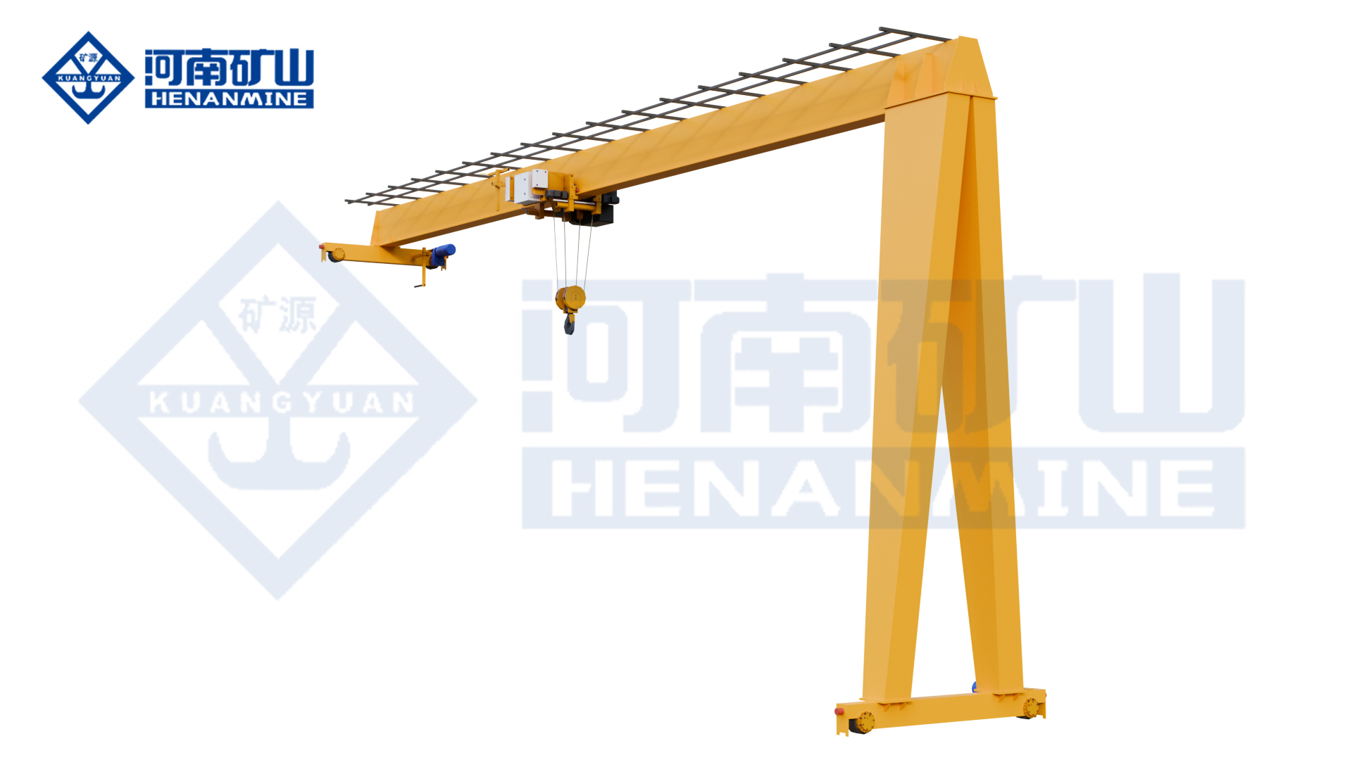
Single-girder electric-hoist handling beside a suitable elevated runway
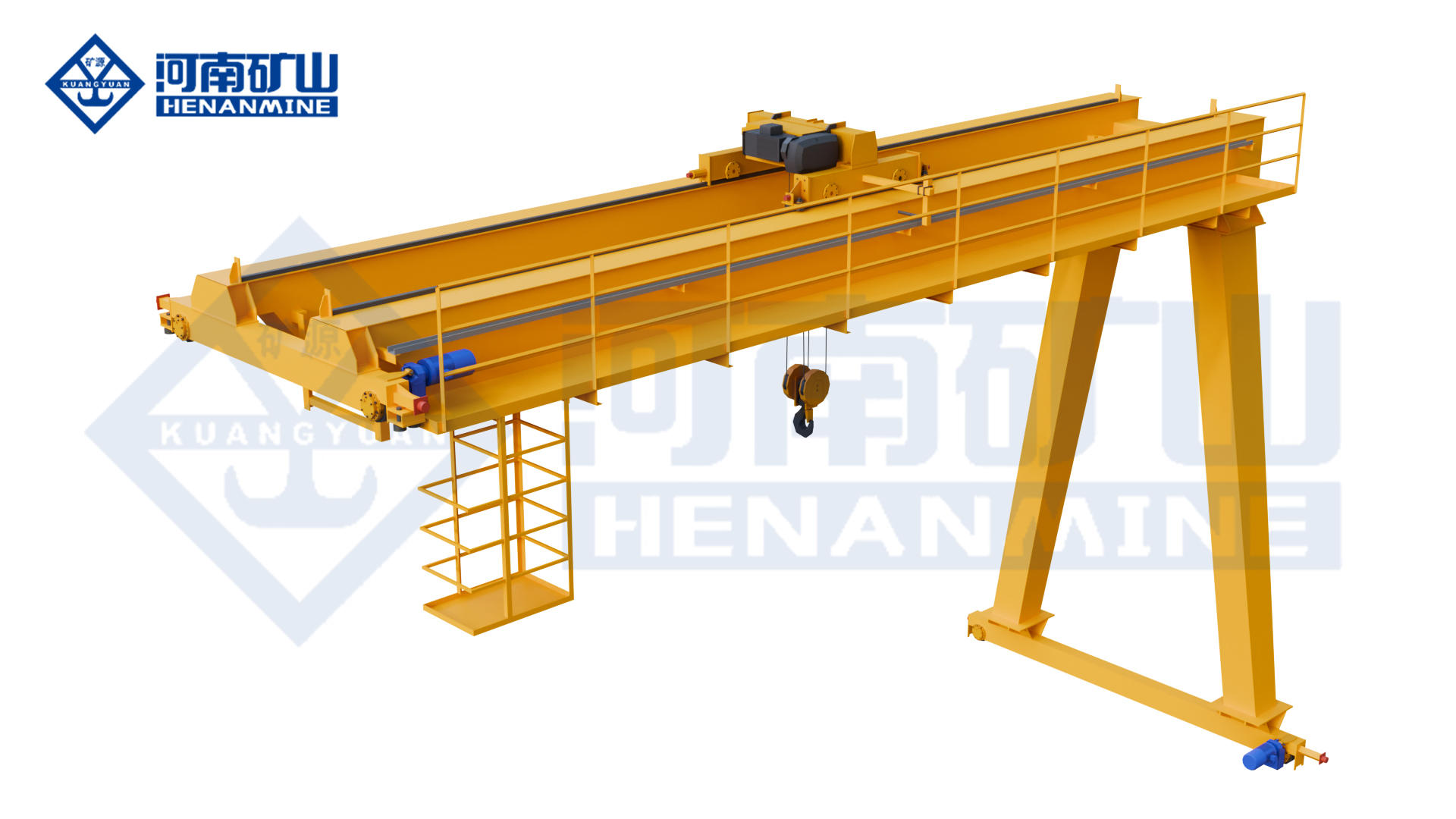
Top-running electric-hoist handling in a semi-gantry working bay
Hook handling beside a suitable elevated runway in workshops and restricted bays
Compare the handling task, selected lifting equipment and supply scope before ordering.
MB₁ runs with one elevated runway and one ground-supported side. MHS uses ground-level supporting runways on both sides.
It can be considered when the existing runway and its supporting structure suit the selected crane reactions and operating duty. Rail size alone is not enough to establish compatibility.
MB₁ uses a double-girder bridge with an electric-hoist trolley. Compare its trolley arrangement, upper hook position, working span and duty when considering a single-girder semi-gantry alternative.
Both are double-girder electric-hoist semi-gantries. MBES is the new-design arrangement, while MB₁ provides the conventional double-girder route.
A shared area is possible only where vehicle and crane movements have a workable layout. The rail, travelling leg, wheels and stopping positions occupy part of that corridor.
PLC-linked control is an available configuration alongside pendant, remote and cabin arrangements. Define the required signals and operating responsibilities so the crane functions fit the production sequence and operator visibility.
Grab and electromagnetic configurations serve different materials, but each requires a matching hoist, attachment interface and electrical package. Attachment self-weight and material carried must be included when establishing useful payload and duty.
Provide the typical load, heaviest complete load, lifts per hour and shift pattern. This describes the duty more usefully than capacity alone and helps match MB₁ to intermittent, repeated handling.
Tell us what you lift, the approximate span, the required lifting height and your destination. If a dimension is unknown, describe the task and leave that field open.