
Billet, bar and section storage
Transfer compatible long steel between receiving and storage positions where rows face different directions. Define minimum and maximum lengths, piece count, pickup spacing and the stack positions the beam must reach.
Bridge cranes for workshops and production lines.
Explore Overhead Cranes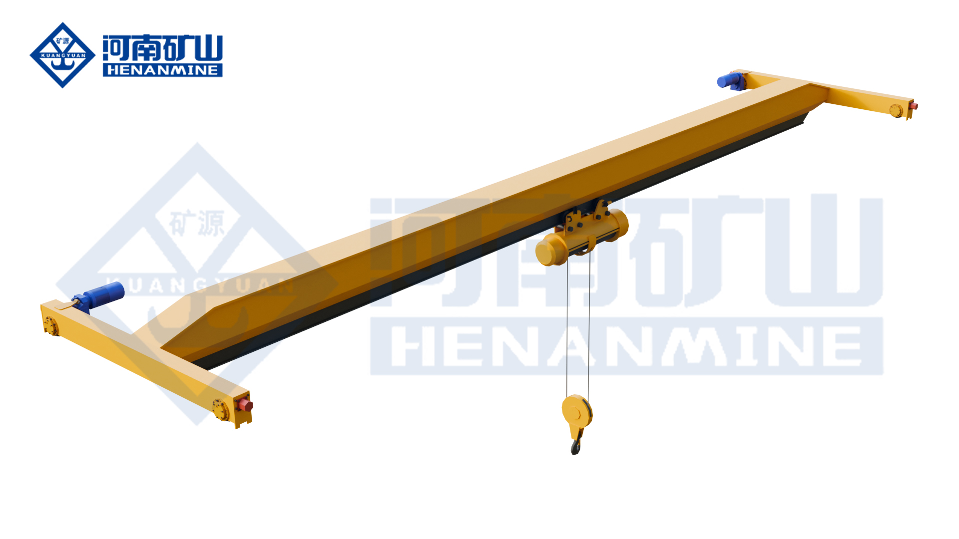
Ground-supported lifting for yards and construction.
Explore Gantry Cranes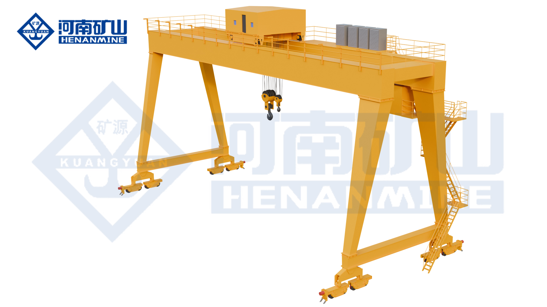
Wire rope and chain hoists for lifting points and cranes.
Explore Electric Hoists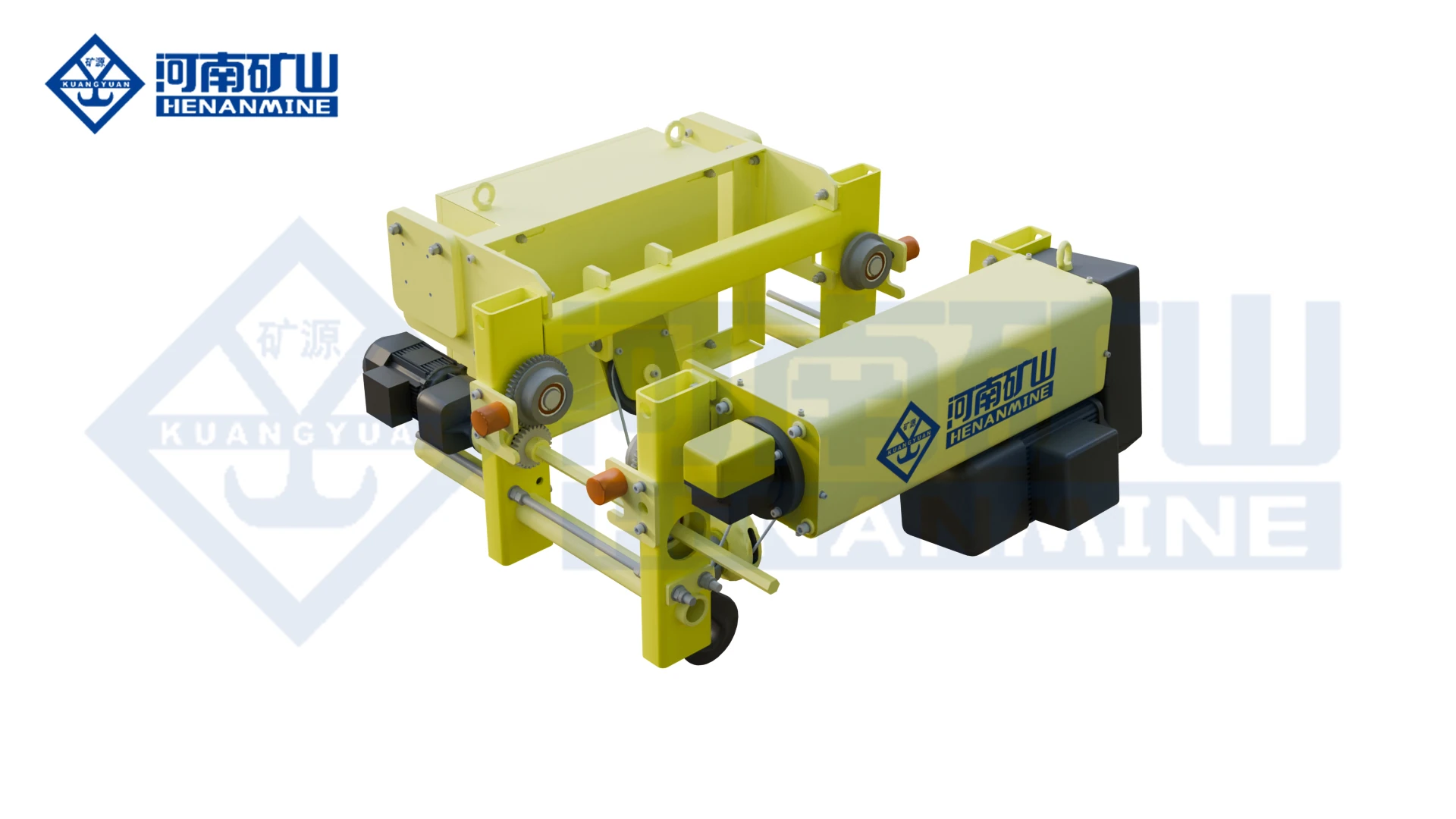
Wire rope lifting and pulling with a powered drum.
Explore Electric Winches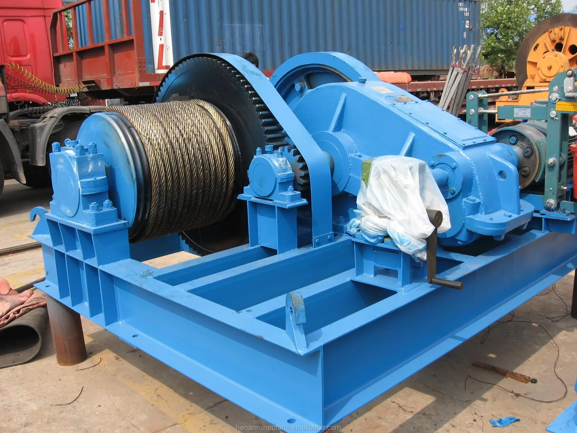
Grab buckets, magnets and hooks for your load.
Explore Lifting Attachments & Grabs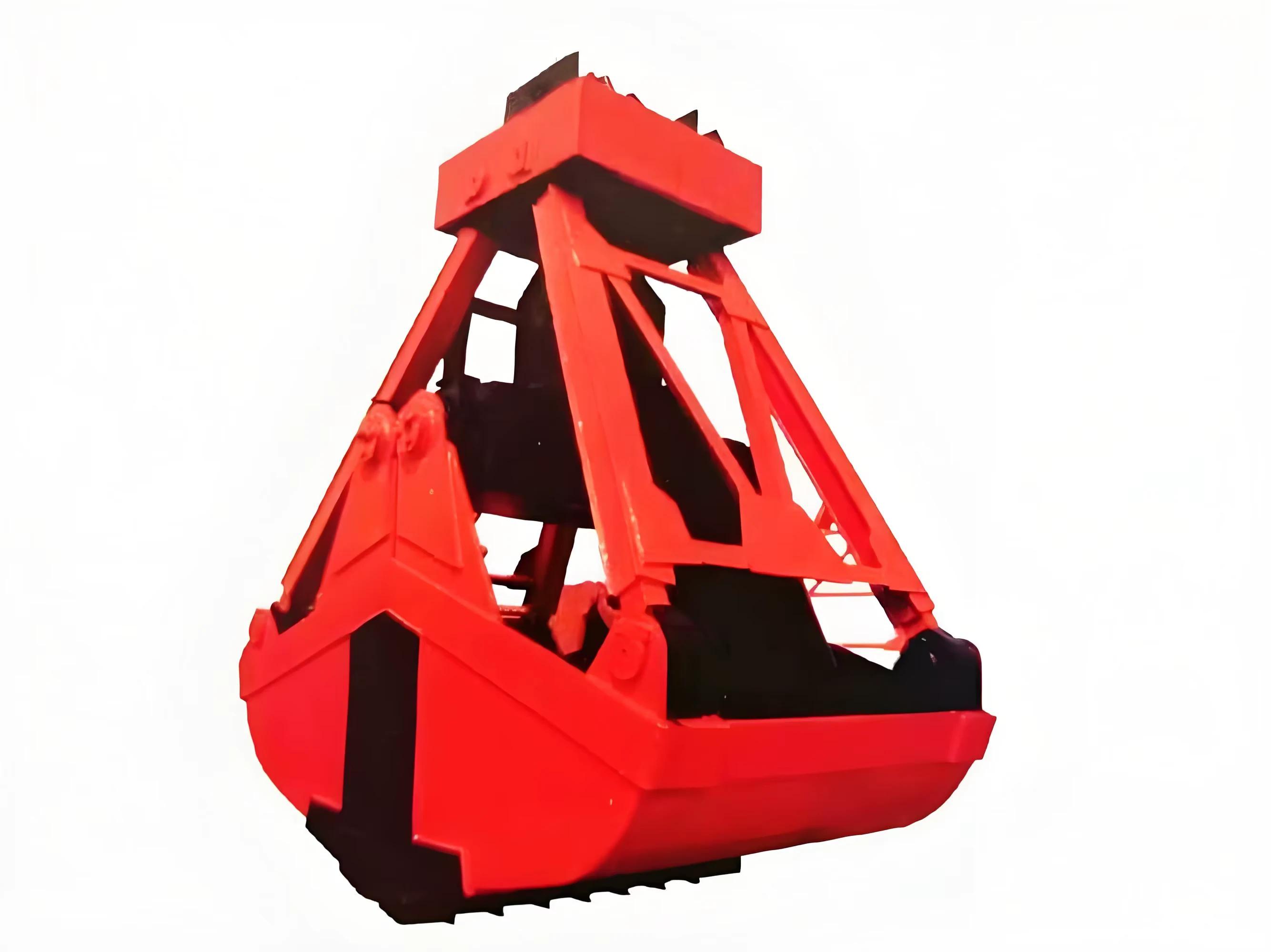
Mobile handling for containers, precast and yard loads.
Explore Rubber-Tired Gantry Cranes & Straddle Carriers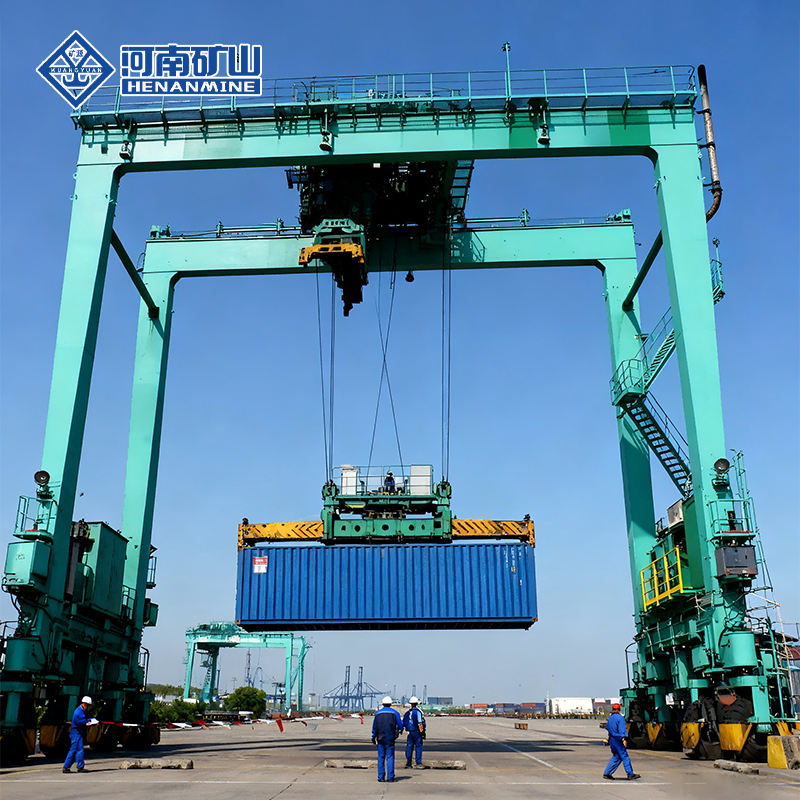
Lift and move vessels through boatyards and marinas.
Explore Marine Travel Lifts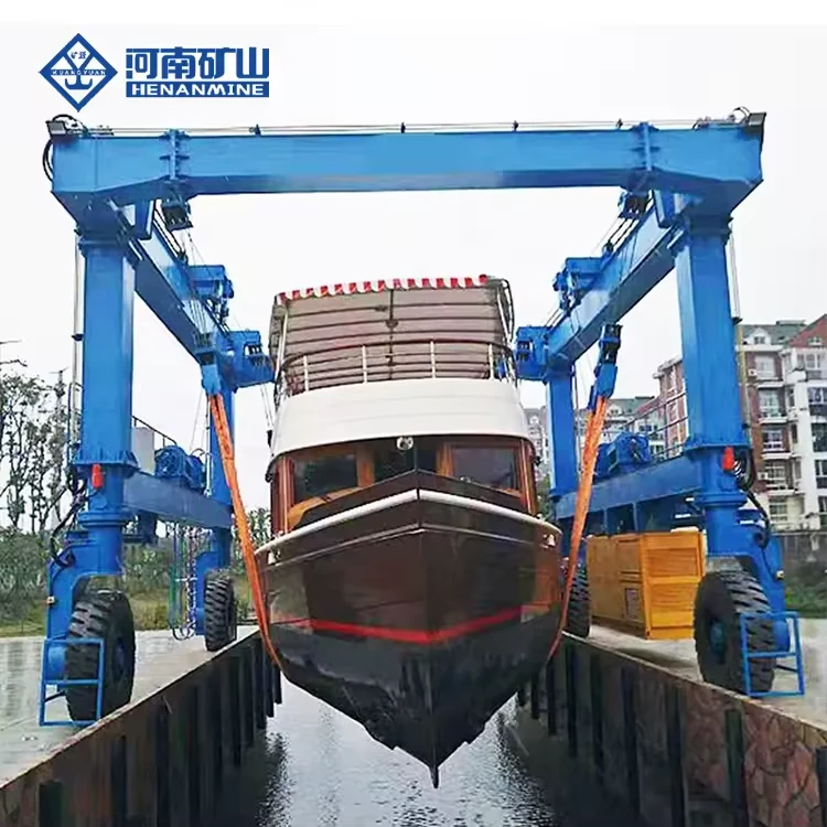
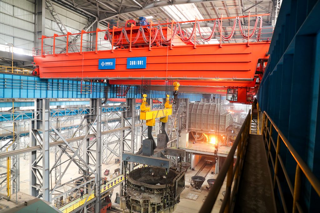
Ladle, slab, scrap and coil handling across steel production.
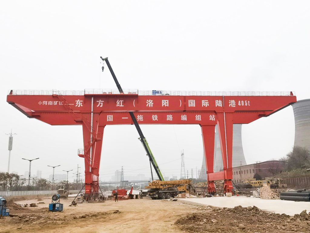
Container stacking and cargo transfers across terminals and rail.
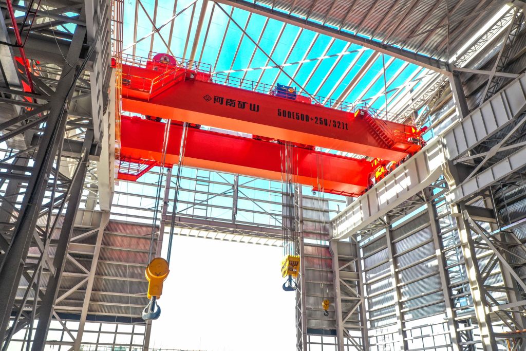
Turbine installation, powerhouse maintenance and wind equipment assembly.
Controlled component transfer and positioning for precision assembly.
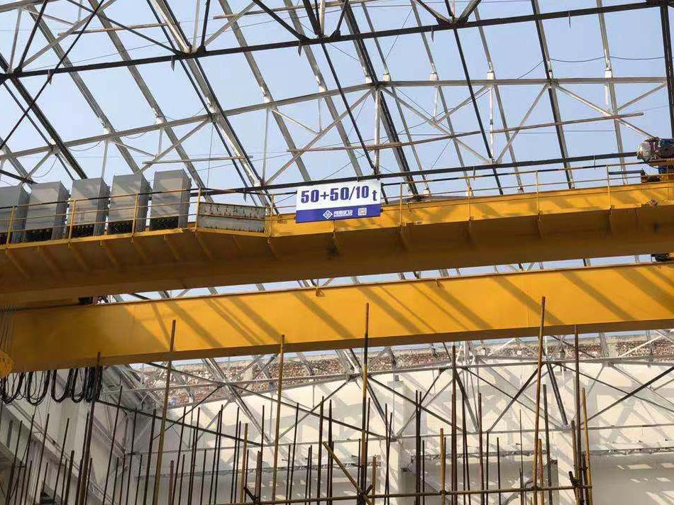
Heavy fabrication, production lifting and factory crane automation.
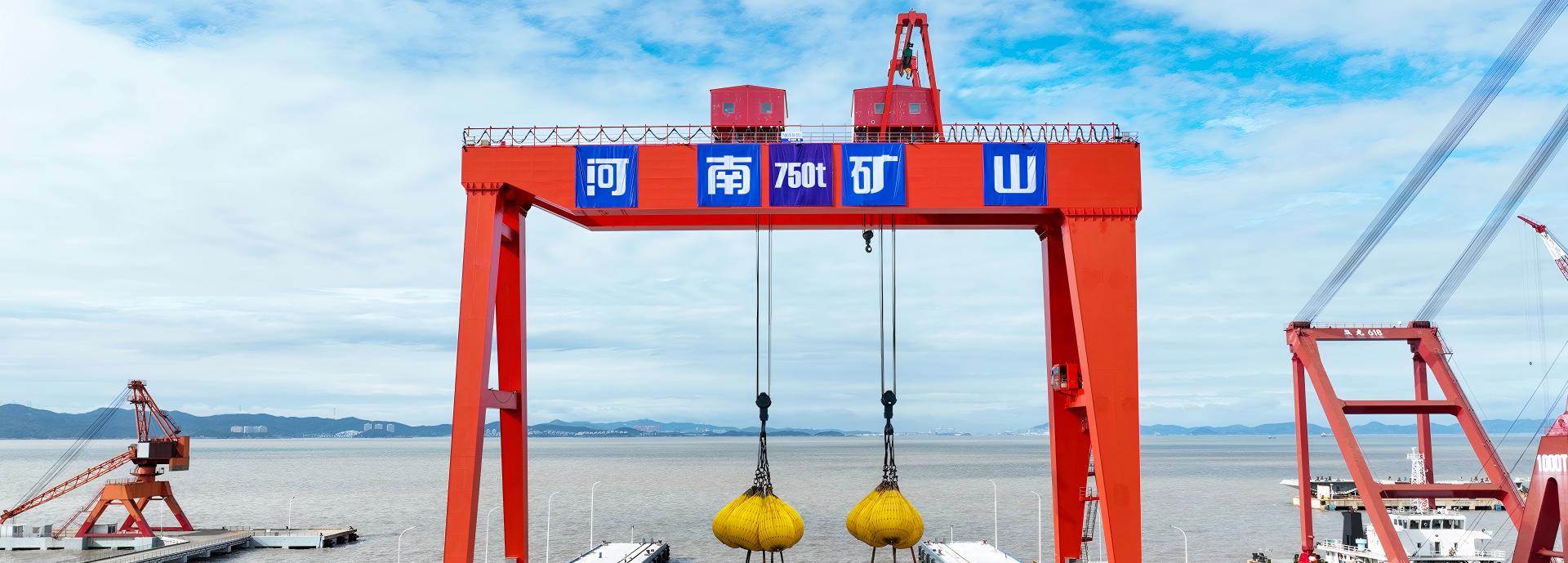
Process lifting for smelters, carbon blocks and anode materials.
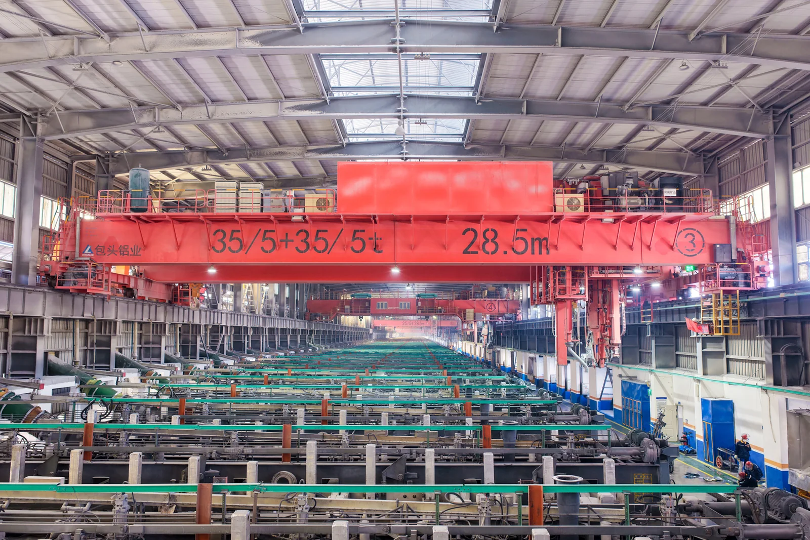
Clean lifting and classified protection for sensitive process areas.
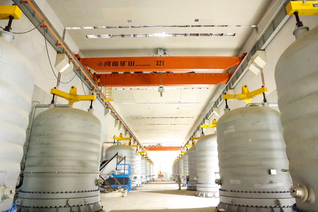
Bridge fabrication, metro construction and ship block assembly.
Automated storage and retrieval for plates, cables and bins.
Follow project dispatches, crane engineering and factory acceptance.
Dispatch, installation and equipment in service
Crane configurations and handling technology
Factory inspections, acceptance and test programmes

Company developments, people and community programmes
Pick up long steel along a magnetic carrier beam, then turn it toward the next storage row or production position. YC creates rotation through an upper trolley running on a circular track above the lower trolley. Match the steel range, complete suspended load and turning space to one coordinated lifting, travel and rotation package.

Start with the information you already have. A load drawing and workshop sketch help us recommend a configuration.
Upper-trolley rotation turns the suspended beam and product toward storage rows, a process station or dispatch position. Plan the turn together with bridge and trolley travel around the actual pickup and landing directions.
Select beam length, magnet quantity and spacing around the shortest and longest products. The magnetic contact pattern follows material grade, stiffness, surface condition and the required single-piece or batch pickup.
Assess lifting, travel, rotation, magnet power and controls in one technical offer. Separate net steel payload from beam and magnet weight, then check the selected arrangement against headroom, runway reactions and maintenance access.
Transfer compatible long steel between receiving and storage positions where rows face different directions. Define minimum and maximum lengths, piece count, pickup spacing and the stack positions the beam must reach.
Present steel to a cutting, preparation or production station in the required horizontal orientation. Include product support, allowable overhang, pickup surface and the landing clearance around process equipment in the handling brief.
Coordinate pickup, travel and orientation change between storage and loading positions. Give the actual landing height, access and visibility so the selected motion speeds and controls support the intended production cycle.
The listed lifting selections include the carrier beam and dedicated attachments. The quotation states usable steel payload, magnet conditions and permitted load distribution for the selected complete arrangement.
Compare the available options for your lifting task. Capacity, span, lift height and speed are matched in the selected configuration.
| Model | YC |
|---|---|
| Lifting arrangement | Upper trolley rotates on a circular track above the lower trolley |
| Listed lifting selections | 5+5 / 10+10 / 16+16 / 25+25 t; includes carrier beam and dedicated attachments |
| Listed span selections | 25 / 28.5 / 33 / 34 m, paired to capacity and duty in the configuration table |
| Listed lifting heights | 10 / 12 / 16 m, paired to the selected configuration |
| Listed working duty | A6 / A7 according to configuration |
| Listed hoisting speeds | 12.4 / 12.6 / 14.8 / 16 / 15.4 m/min by configuration |
| Listed trolley travel | 39–48 m/min by configuration |
| Listed bridge travel | 85.2–107 m/min by configuration |
| Listed beam rotation speed | 1.36–1.85 r/min by configuration |
| Rotation range | Up to 360° upper-trolley rotation; ordered range matched to the material route |
| Magnet holding on power loss | 15–30 minute battery-holding package; duration and test conditions specified with the order |
| Control | PLC/HMI; variable-frequency motion and anti-sway functions selected for the handling task |
| Listed configuration supply | 380 V / 50 Hz, three-phase; destination electrical package can be specified |
| Operating environment | Listed numeric combinations: indoor; outdoor, temperature and dust package specified separately |
| Power calculation | Crane drive power and magnet/attachment power identified separately |
The listed 15–30 min battery-holding time is a manufacturer reference. Confirm the supplied magnet, holding load and contact conditions, required duration, monitoring and acceptance test in the order. Backup magnet supply does not establish powered crane travel.
| Lifting rating | Duty | Span | Lift | Hoisting speed | Trolley travel | Rotation speed |
|---|---|---|---|---|---|---|
| 5+5 t | A6 | 28.5 m | 12 m | 12.4 m/min | 44.2 m/min | 1.5 r/min |
| 10+10 t | A7 | 25 m | 16 m | 12.6 m/min | 42.2 m/min | 1.36 r/min |
| 10+10 t | A7 | 34 m | 16 m | 12.6 m/min | 42.2 m/min | 1.36 r/min |
| 16+16 t | A6 | 25 m | 10 m | 14.8 m/min | 39 m/min | 1.36 r/min |
| 16+16 t | A6 | 33 m | 16 m | 16 m/min | 48 m/min | 1.85 r/min |
| 25+25 t | A6 | 25 m | 10 m | 15.4 m/min | 40 m/min | 1.4 r/min |
These are matched indoor upper-rotating arrangements. Lifting ratings include the carrier beam and dedicated attachments. Each span, lift, duty and speed stays with its row; the quotation identifies the usable steel payload and required magnet system.
| Lifting rating | Span / duty | Bridge travel | Maximum wheel load | Crane drive power | Bridge rail |
|---|---|---|---|---|---|
| 5+5 t | 28.5 m / A6 | 102 m/min | 65 kN | 50.2 kW | P43 |
| 10+10 t | 25 m / A7 | 85.2 m/min | 190 kN | 114.8 kW | QU80 |
| 10+10 t | 34 m / A7 | 85.2 m/min | 210 kN | 128.8 kW | QU80 |
| 16+16 t | 25 m / A6 | 106 m/min | 255 kN | 151.3 kW | QU80 |
| 16+16 t | 33 m / A6 | 101 m/min | 260 kN | 196 kW | QU80 |
| 25+25 t | 25 m / A6 | 107 m/min | 335 kN | 243.5 kW | QU100 |
Crane drive power excludes dedicated magnet and lifting-attachment power. These are indoor configurations; wheel loads and rail selection stay with the listed capacity, span and duty.
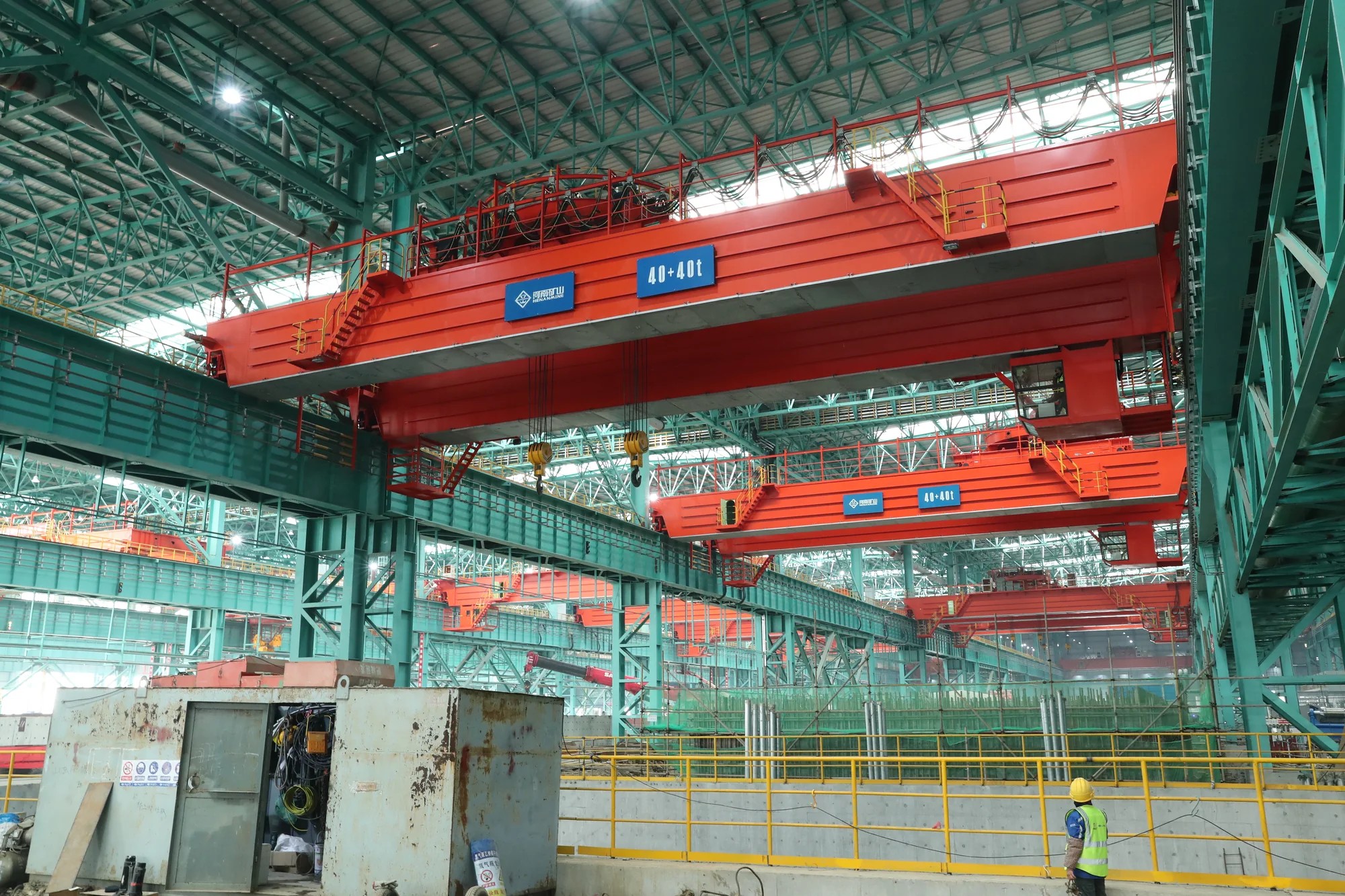
The renderings explain the upper rotating trolley, lower travel trolley and magnetic-beam arrangement. The site photographs document upper-trolley and hook equipment in a production hall. Review the ordered magnetic-beam arrangement for overall height, beam suspension and pickup, rotating clearances and access to the upper-trolley drive and circular track.

Select the steel pickup, upper-trolley geometry and motion package together. Each listed indoor configuration retains its own lifting rating, span, lift, duty and speeds; beam and magnet selection then establishes the usable steel payload.
Provide grade, minimum and maximum dimensions, mass, temperature and contact condition. State single-piece or batch handling, then list steel payload separately from beam, magnets and other suspended equipment.
Show pickup and landing directions and every obstruction within the full beam-and-load sweep. Select the required rotation range, including any up-to-360° arrangement, together with headroom, cable routing and the permitted operating sequence.
Keep capacity, span, lift, duty and motion speeds in the same reference row. Confirm wheel reactions, bridge rail and structural interfaces for the ordered arrangement, including beam weight and load distribution.
Identify magnet quantity, spacing, excitation supply, cable equipment and release functions. Distinguish crane-drive power from magnet and attachment power, with the destination voltage and site connection responsibilities stated in the offer.
Specify the required magnet holding period, representative load conditions, battery monitoring and alarms. Define the operator response and the functions supported after mains loss; any powered recovery movement has its own supply and control scope.
Select PLC/HMI, variable-frequency motion and any positioning or process interfaces around the operating cycle. Agree performance checks with the load and motion conditions, and provide inspection access for rotation drives, brakes, ropes and cables.
Compare the upper-trolley crane, magnetic lifting package and site services on the same scope schedule. Named equipment, approved drawings and agreed test conditions make quotations and handover easier to assess.
List the bridge, lower travel trolley, upper rotating trolley, beam, magnets, rigging and controls. Identify excitation equipment, backup holding, cable systems and site power feed, with rails, runway steelwork and installation services clearly allocated.
Request complete load and net payload, attachment weights, magnet data, turning envelope, approach dimensions, wheel reactions and runway requirements. Include crane and trolley drawings, electrical documents, operating limits and maintenance instructions.
Define representative steel, pickup and release checks, rotation limits and the planned load distribution. Include lifting and travel functions, ordered control interfaces and the power-loss holding test, with factory and site responsibilities stated before manufacture.
Set milestones for material selection, beam and magnet approval, arrangement approval, manufacture, factory checks and dispatch. Confirm shipping divisions, packing, access for unloading and storage so the delivery programme reflects the actual equipment and site readiness.
Allocate erection, trolley assembly, rope and cable setup, electrical connection and test material. Include rotation-limit setup, pickup and release, operator training and the agreed power-loss procedure in the site commissioning scope.
Agree warranty commencement and coverage, service contacts and recommended spares. Include upper-trolley drive and circular-track inspection, brakes, ropes, magnet cables, sensors and battery testing in the maintenance handover.
Send the product range, net pickup target, contact conditions and pickup-to-landing directions.
Check complete load, upper-trolley headroom, turning space, selected motions and runway interfaces.
Approve beam and magnets, power-loss response, documents, tests and delivery and site-service boundaries.
Commission pickup, travel, rotation and release with the representative load and train the operating team.
Technical schedule · General arrangement · Attachment interface · Runway loads · Electrical information · Safety-function description · Agreed inspection records · Operation and maintenance manuals

Support long ferromagnetic steel at several magnetic pickup points along a carrier beam. QL combines the bridge, lifting arrangement, beam and magnets for plate, ingots and sections whose length and stiffness call for distributed support. Select beam length, magnet spacing and any rotation from the full product range and the route between pickup and landing.
View this arrangement ↗
Lift compatible steel along a magnetic beam and turn it beneath the trolley to match the landing direction. QLC combines a lower rotating electromagnetic carrier beam with photoelectric angle sensing, rotation-limit braking and selected anti-sway controls. Configure the beam, magnets and motion around the complete product range and the space available in your bay.
View this arrangement ↗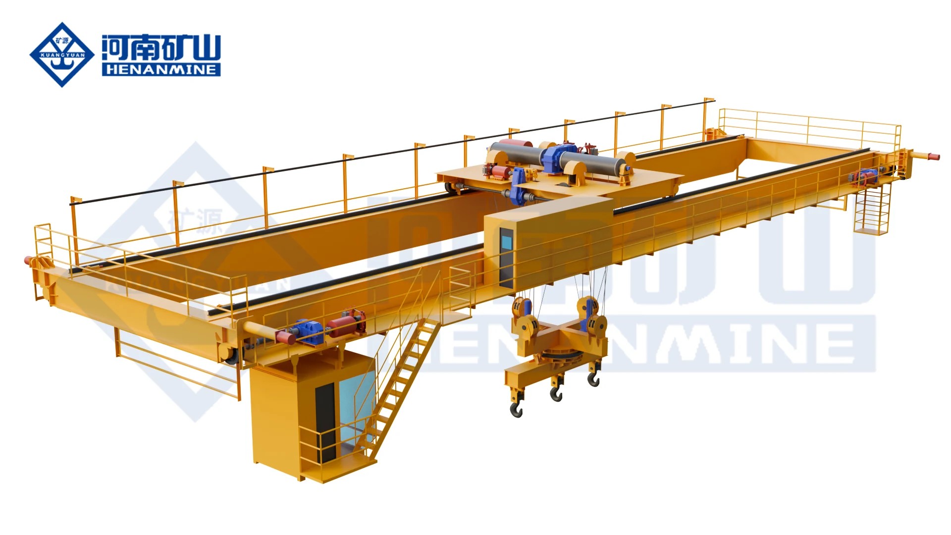
Turn long steel toward its landing position with a lower rotating carrier beam and a selected magnet or mechanical clamp.
View this arrangement ↗Review the lifting task, configuration and quotation scope. We can help develop a crane proposal from the project information available.
An upper trolley turns on a circular track above the lower trolley. The suspended magnetic beam and steel change horizontal orientation with that movement, while the lower trolley travels across the bridge. The arrangement drawing identifies the rotating components and their working clearances.
Compare YC's upper-trolley assembly with the lower suspended rotation arrangement of QLC or QJ for the same load and route. Review overall equipment height, available lift, suspended depth, full turning envelope, cable routing and maintenance access. The preferred mechanism follows the bay and handling task.
The paired marking identifies a complete lifting selection with a permitted load distribution. It does not establish a free 20 t steel pickup. The listed ratings include the carrier beam and dedicated attachments; ask for their weights, the selected magnets' pickup conditions and the explicit usable steel payload.
The six reference combinations are matched arrangements. For example, the listed 10+10 t A7 configurations use 25 or 34 m span, 16 m lift and 12.6 m/min hoisting. Keep each row's duty, speeds, wheel reactions and rail selection together when comparing a proposal.
An up-to-360° upper-trolley arrangement is available, with the permitted range and cable arrangement stated for the order. Horizontal rotation changes the direction the steel faces in plan. If you need repeated continuous rotation, tilting or inversion, describe that sequence explicitly so its mechanism and services can be assessed.
It refers to a selected battery-backed magnet-holding package. The order establishes the actual duration, magnet load, contact conditions, battery condition, monitoring and test method. It is not a standard holding guarantee for every YC configuration, and it does not by itself power crane travel or a complete recovery movement.
Provide the shortest and longest products, section or plate dimensions, grade, temperature, contact surface and pieces per lift. Beam length, magnet spacing and controls must suit that range. Thin plate, scale, curvature, gaps and a single-sheet requirement need their own pickup assessment and representative verification.
Describe pickup, lifting, travel, turning, approach and release, with representative load and travel distances. State any required stopping or residual-sway check together with its measurement method and operating conditions. The selected motion controls and process signals can then be evaluated against the same complete cycle.
Request crane-drive power separately from magnet and attachment power, plus destination supply, starting and control requirements and site-feed boundaries. For the runway, use the ordered configuration's wheel reactions, rail selection and arrangement dimensions. The matched reference rows provide a starting point for that review.
The complete load, span, lift, upper trolley, rotation range, beam and magnet layout, control package and backup holding define the equipment. Compare documentation, acceptance, packing, freight, erection, commissioning, training and spares as named items. Agree delivery milestones against approved engineering inputs and the site's readiness.
Tell us which steel you move, how much must be picked up and how its direction changes. We can prepare a YC proposal around the complete beam, magnet and upper-trolley arrangement.
info@cranehenanmine.com