
Orient the plan
Use length for the runway travel direction and width for the bridge span direction.
Bridge cranes for workshops and production lines.
Explore Overhead Cranes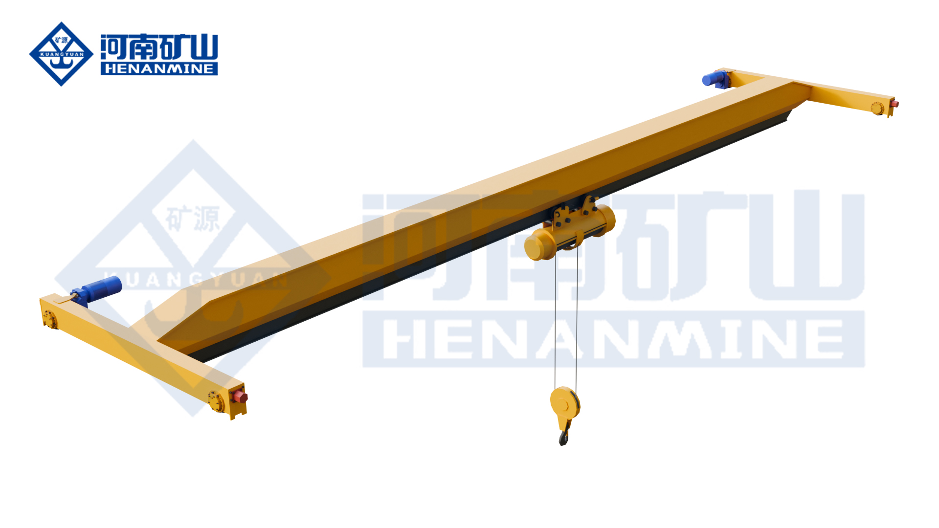
Ground-supported lifting for yards and construction.
Explore Gantry Cranes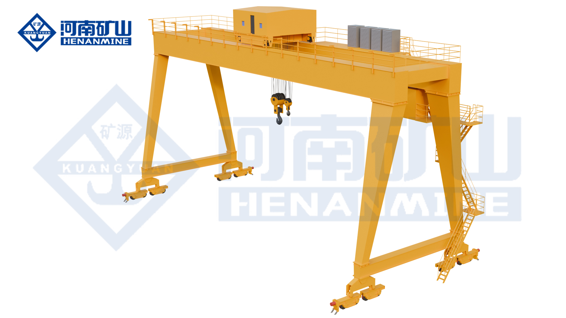
Wire rope and chain hoists for lifting points and cranes.
Explore Electric Hoists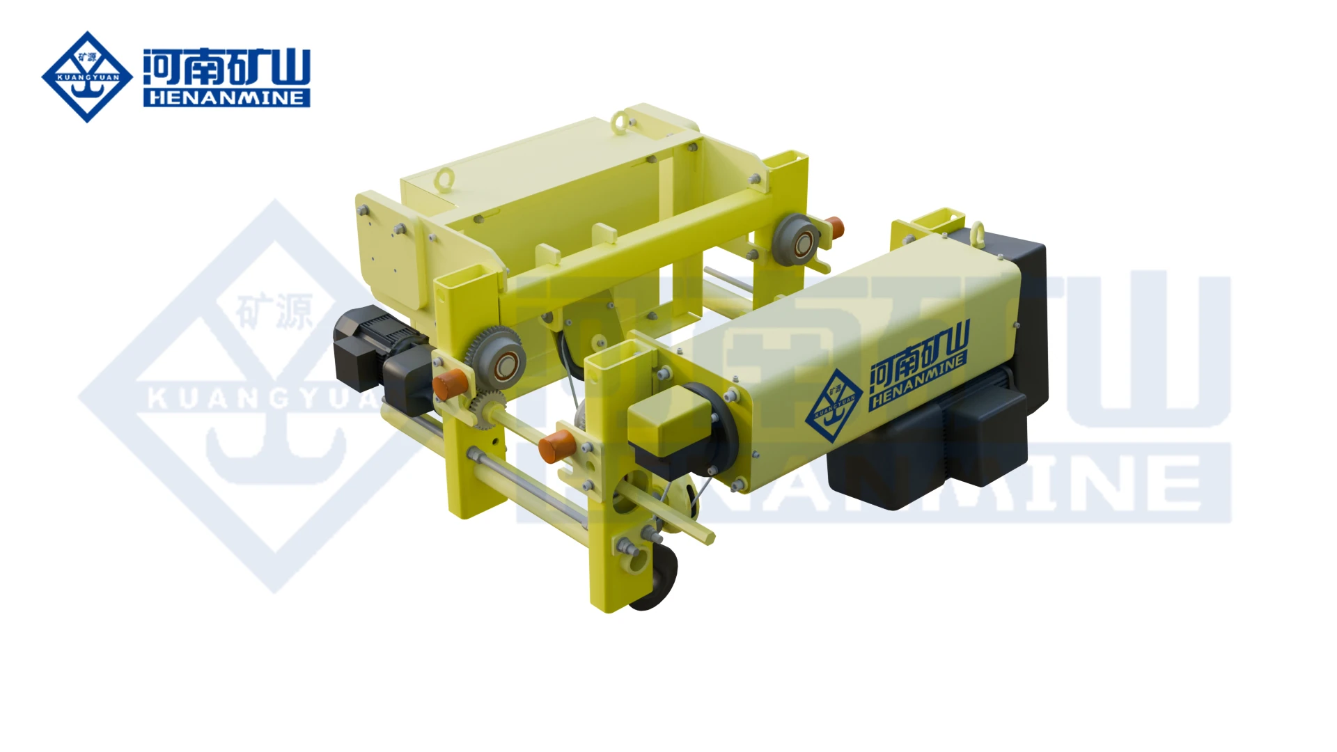
Wire rope lifting and pulling with a powered drum.
Explore Electric Winches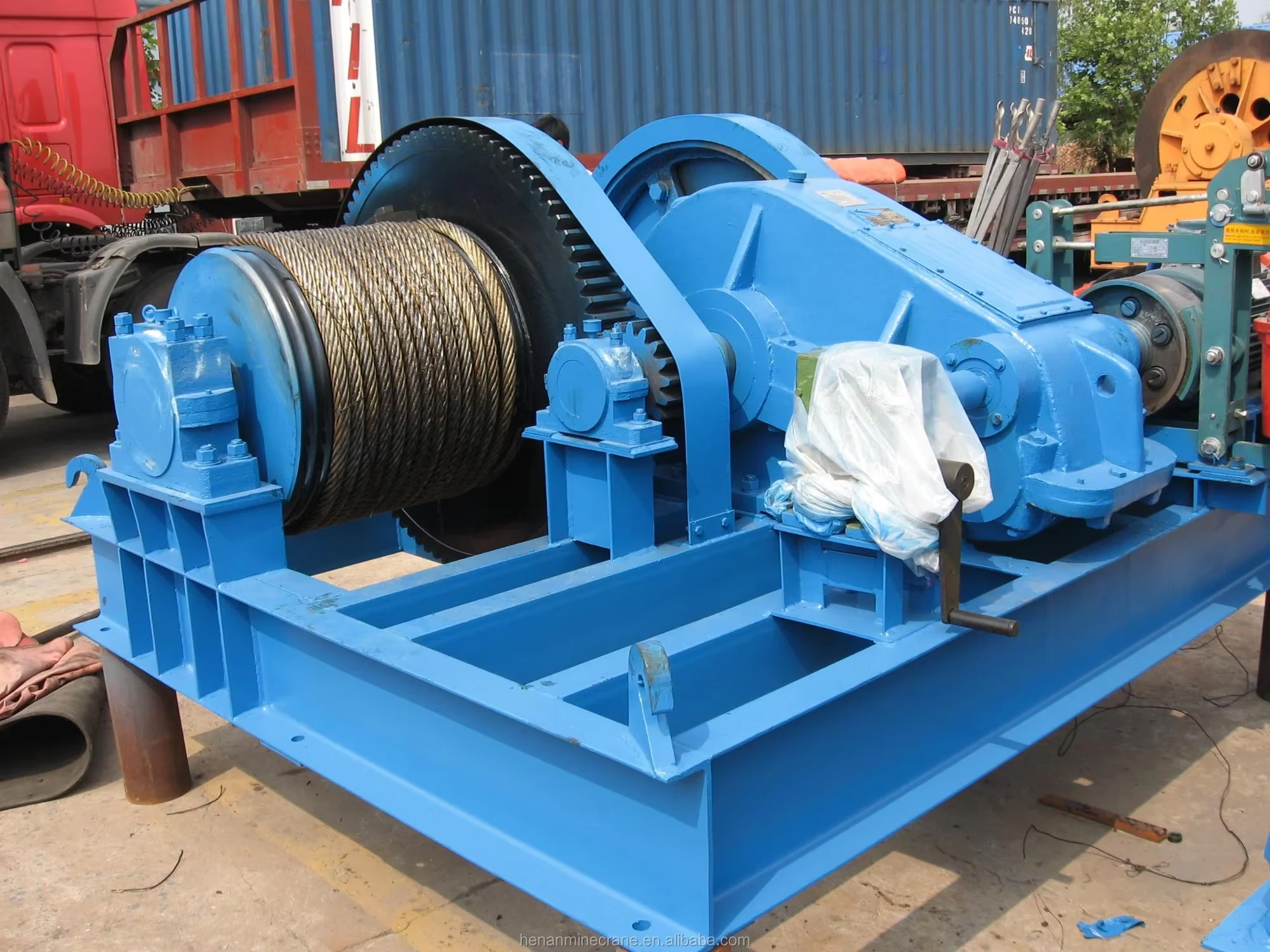
Grab buckets, magnets and hooks for your load.
Explore Lifting Attachments & Grabs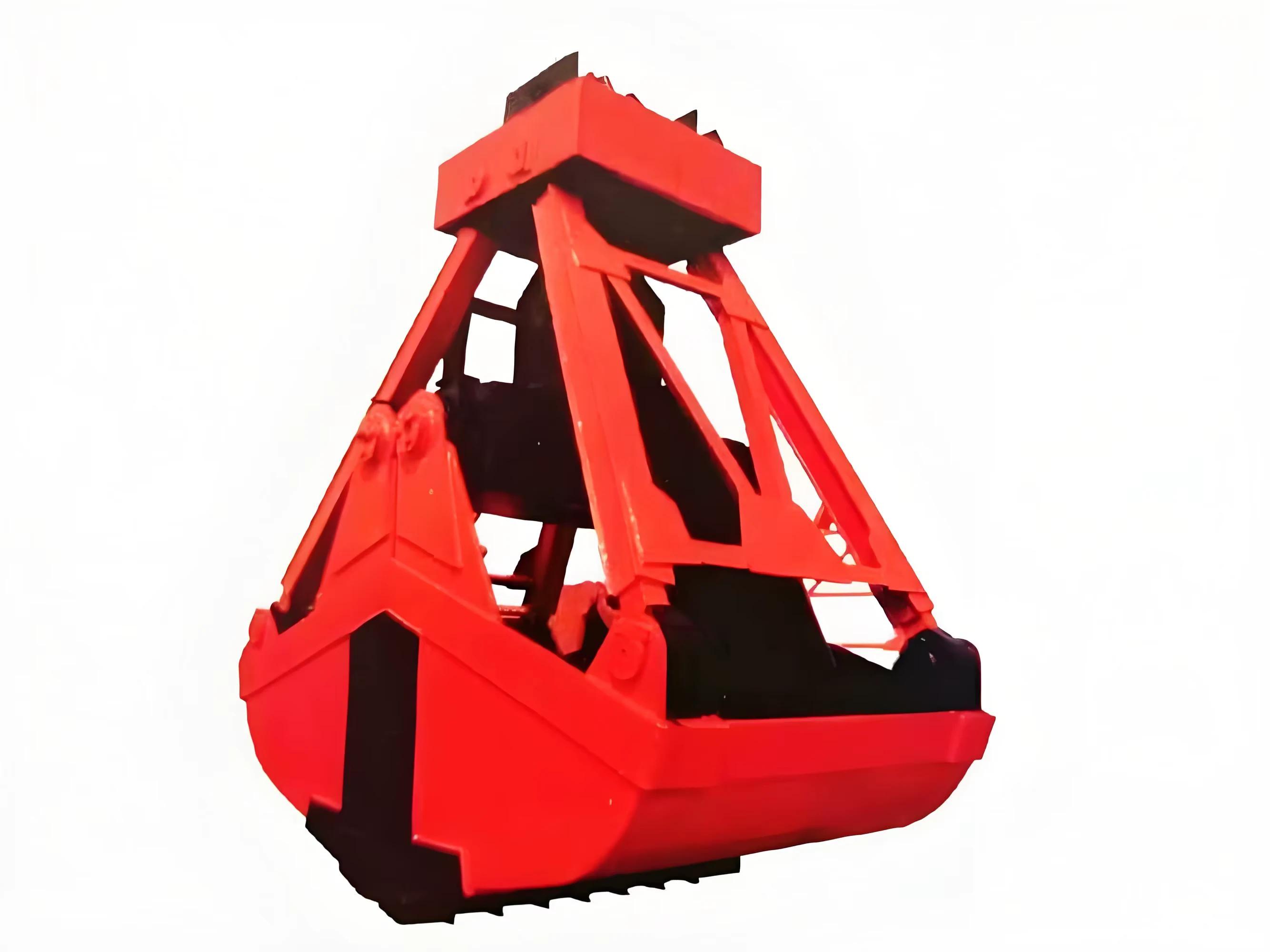
Mobile handling for containers, precast and yard loads.
Explore Rubber-Tired Gantry Cranes & Straddle Carriers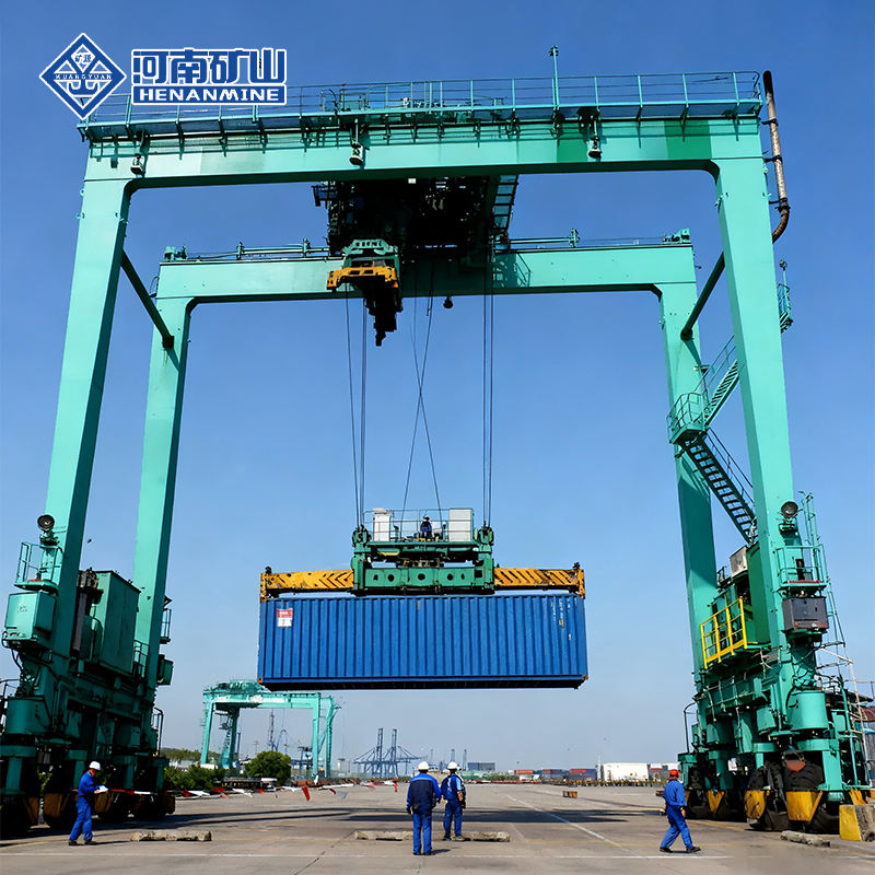
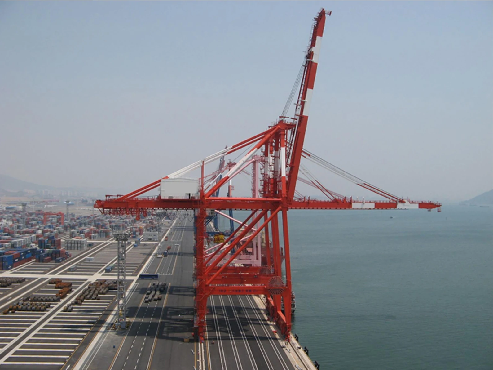
Lift and move vessels through boatyards and marinas.
Explore Marine Travel Lifts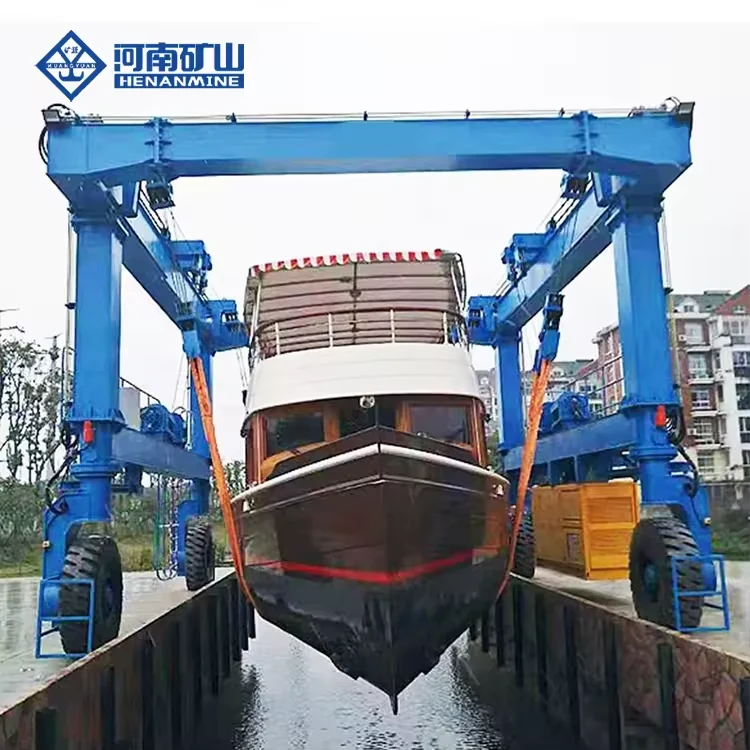
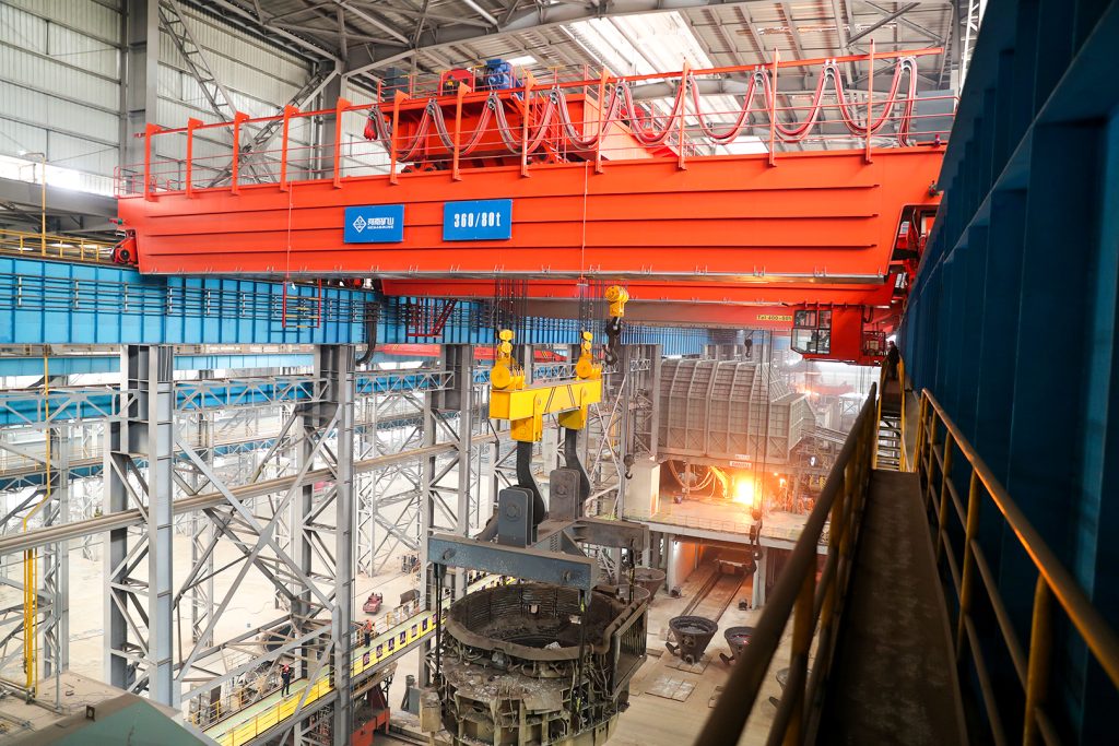
Ladle, slab, scrap and coil handling across steel production.
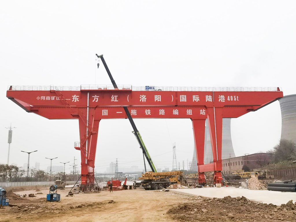
Container stacking and cargo transfers across terminals and rail.
Turbine installation, powerhouse maintenance and wind equipment assembly.
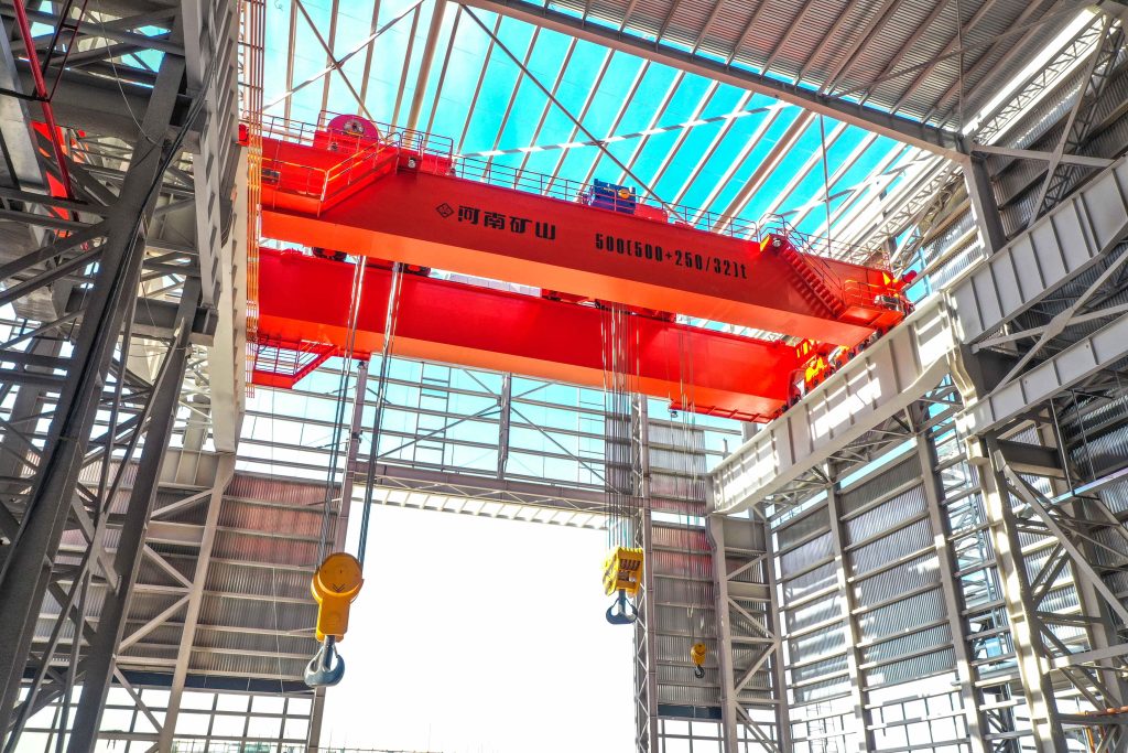
Controlled component transfer and positioning for precision assembly.
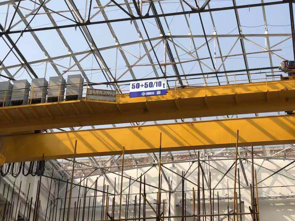
Heavy fabrication, production lifting and factory crane automation.
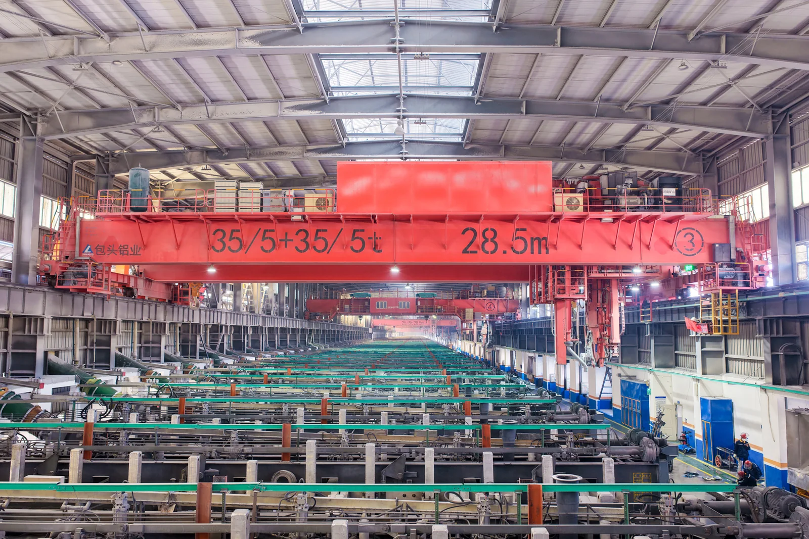
Process lifting for smelters, carbon blocks and anode materials.
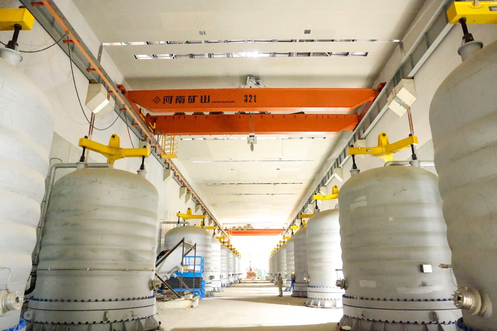
Clean lifting and classified protection for sensitive process areas.
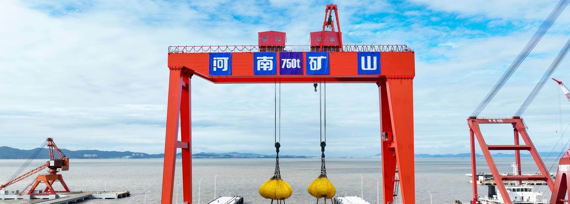
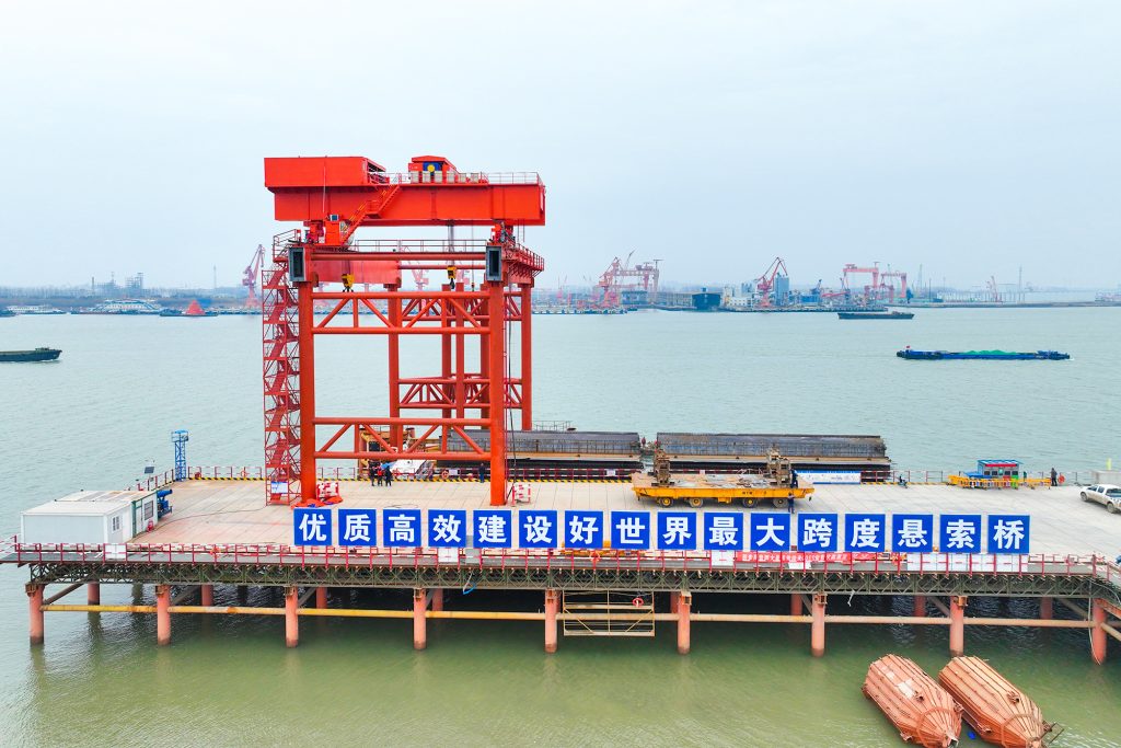
Bridge fabrication, metro construction and ship block assembly.
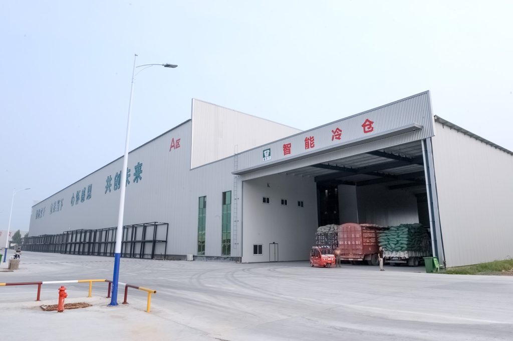
Automated storage and retrieval for plates, cables and bins.
Follow project dispatches, crane engineering and factory acceptance.
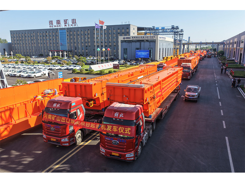
Dispatch, installation and equipment in service
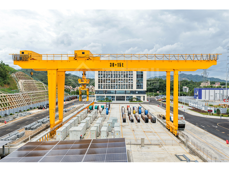
Crane configurations and handling technology
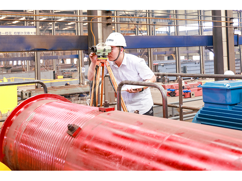
Factory inspections, acceptance and test programmes

Company developments, people and community programmes
Use this to compare the proposed hook working area with a rectangular workshop before finalising workstation positions or requesting a layout drawing.
Use length for the runway travel direction and width for the bridge span direction.
Measure each approach from its corresponding workshop boundary to the hook centre at the travel limit.
Check covered length, covered width and area. Mark obstructions and the footprint of the actual load separately on your plan.
Length 30 m; width 12 m; end approaches 1 m and 1.2 m; side approaches 0.8 m and 0.8 m.
The hook-centre coverage is 27.8 m by 10.4 m, giving 289.12 m², or about 80.3111% of the workshop rectangle.
Covered runway length shows the usable hook travel along the bay.
Covered bridge width shows the usable hook travel across the bay; it is not necessarily the crane’s rail-centre span.
Area percentage compares two rectangles. It does not mean every point is accessible with a bulky load or through an obstruction.
Entering the trolley or bridge physical clearance instead of the distance from the workshop boundary to the hook centre at its travel limit.
Covered length = workshop length − near-end approach − far-end approach
Covered width = workshop width − left approach − right approach
Covered area = covered length × covered width
No. It gives the travel-limit rectangle. Mark obstacles, prohibited zones and the load footprint separately.
Yes if your layout defines zero for that boundary, but the calculator does not establish that a proposed crane can actually reach a wall.