
Name the support points
Set A as the left reference and B as the second lifting point. Both reactions must act vertically in this model.
Bridge cranes for workshops and production lines.
Explore Overhead Cranes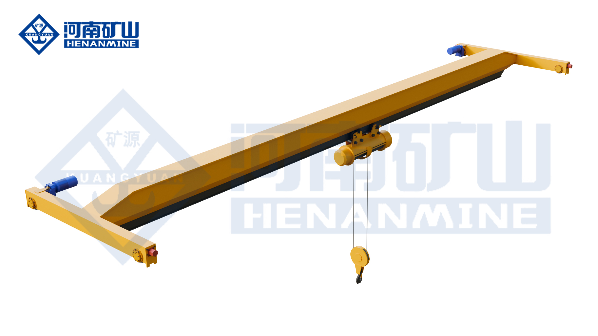
Ground-supported lifting for yards and construction.
Explore Gantry Cranes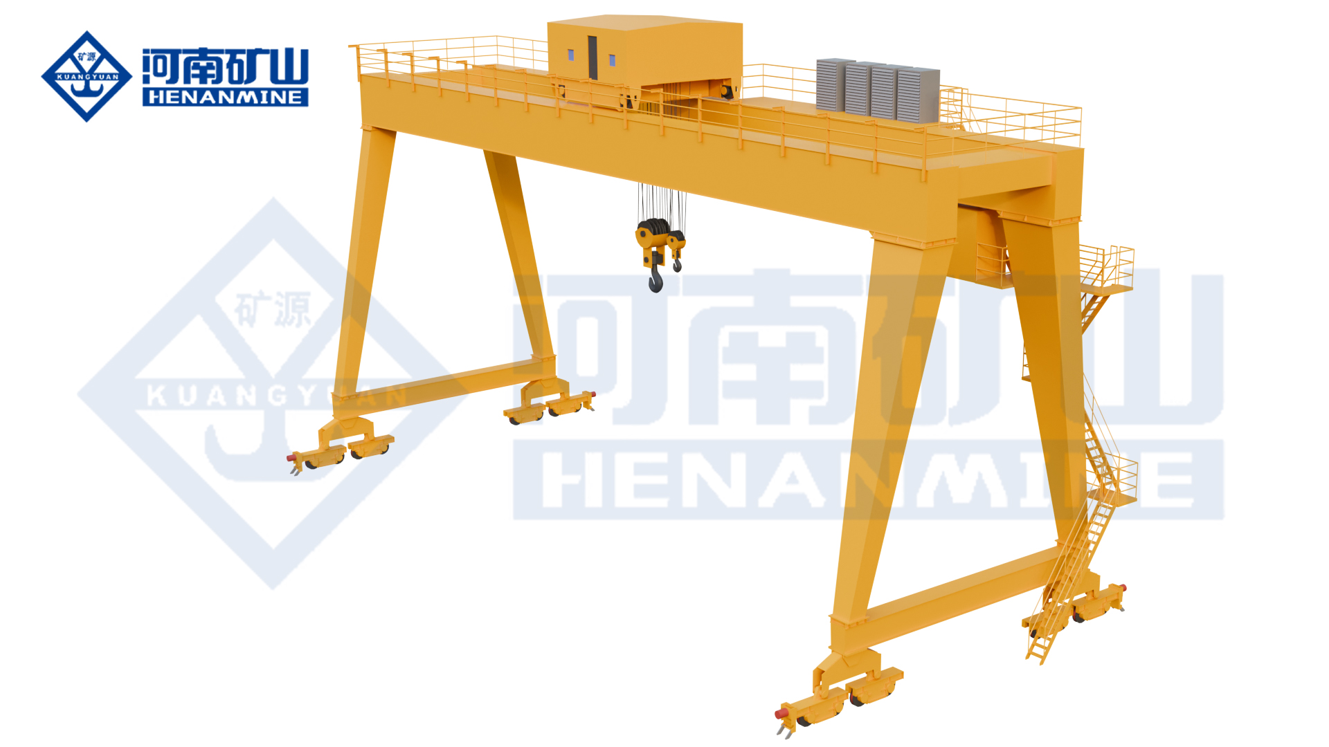
Wire rope and chain hoists for lifting points and cranes.
Explore Electric Hoists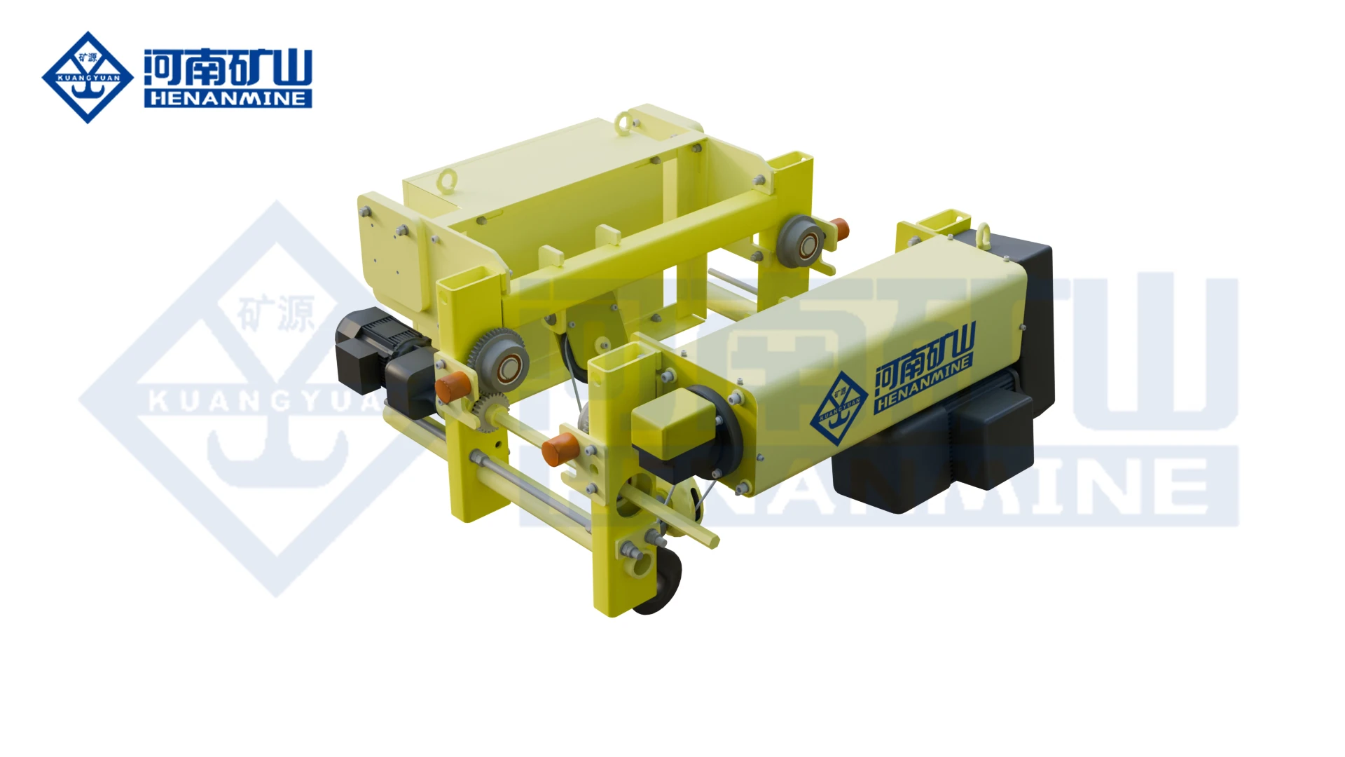
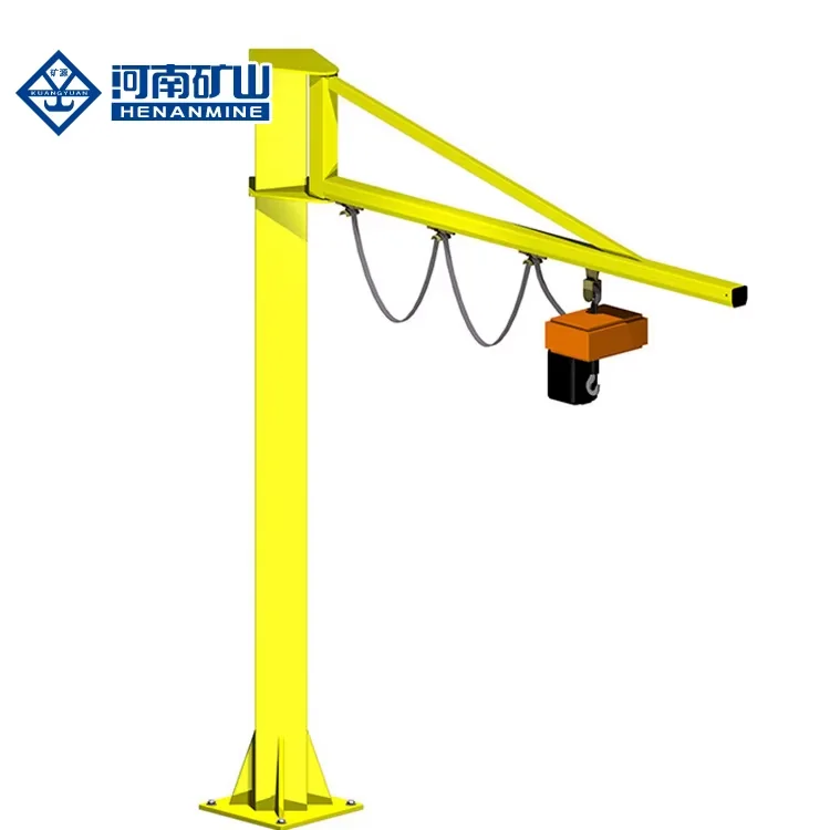
Wire rope lifting and pulling with a powered drum.
Explore Electric Winches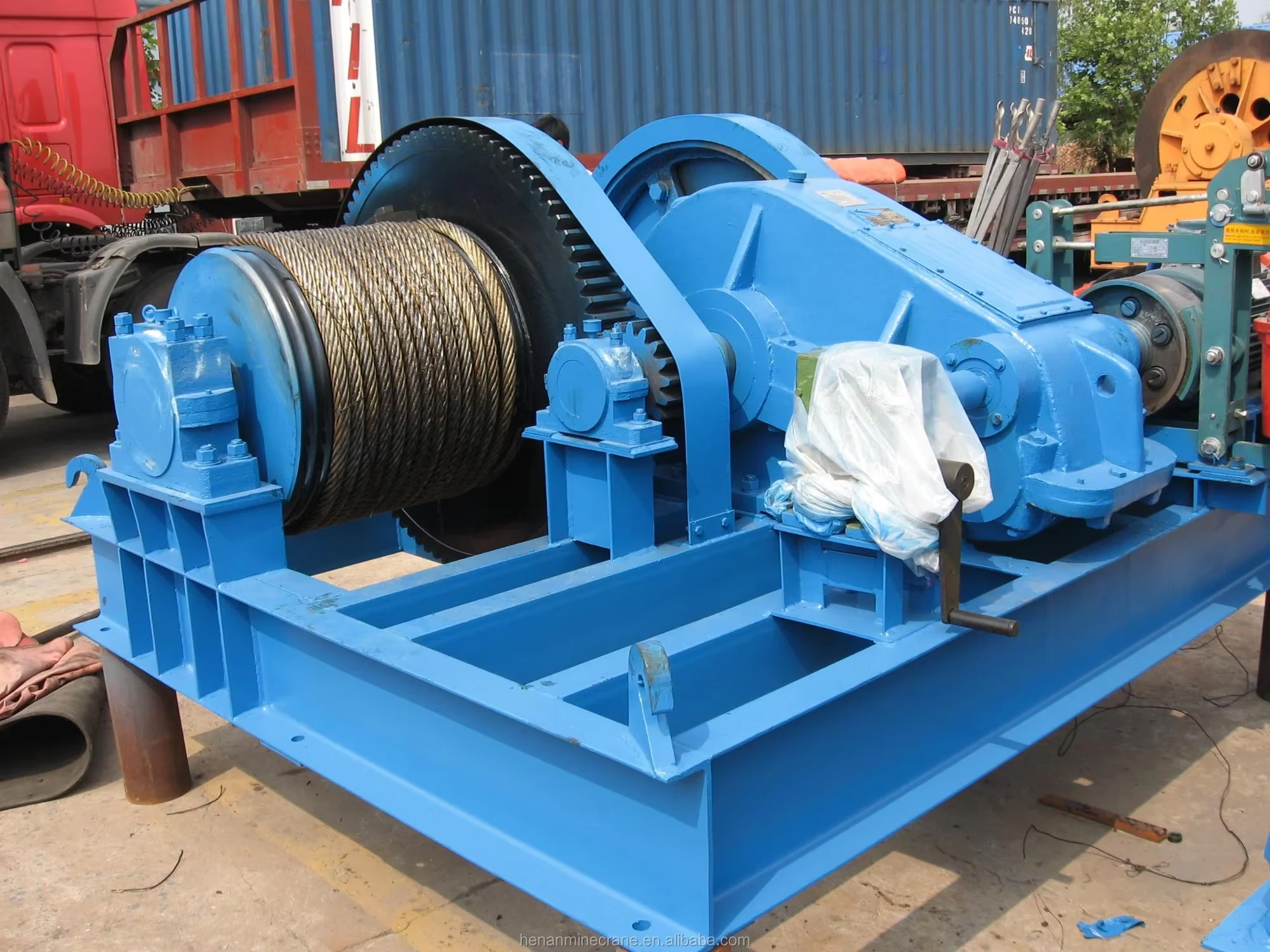
Grab buckets, magnets and hooks for your load.
Explore Lifting Attachments & Grabs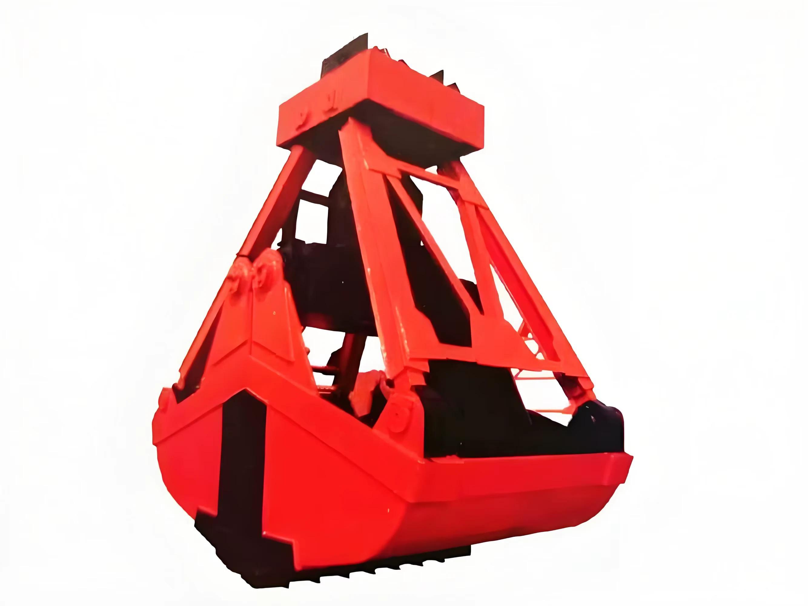
Mobile handling for containers, precast and yard loads.
Explore Rubber-Tired Gantry Cranes & Straddle Carriers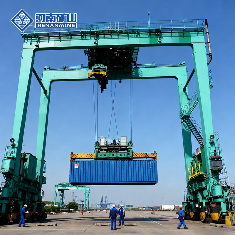
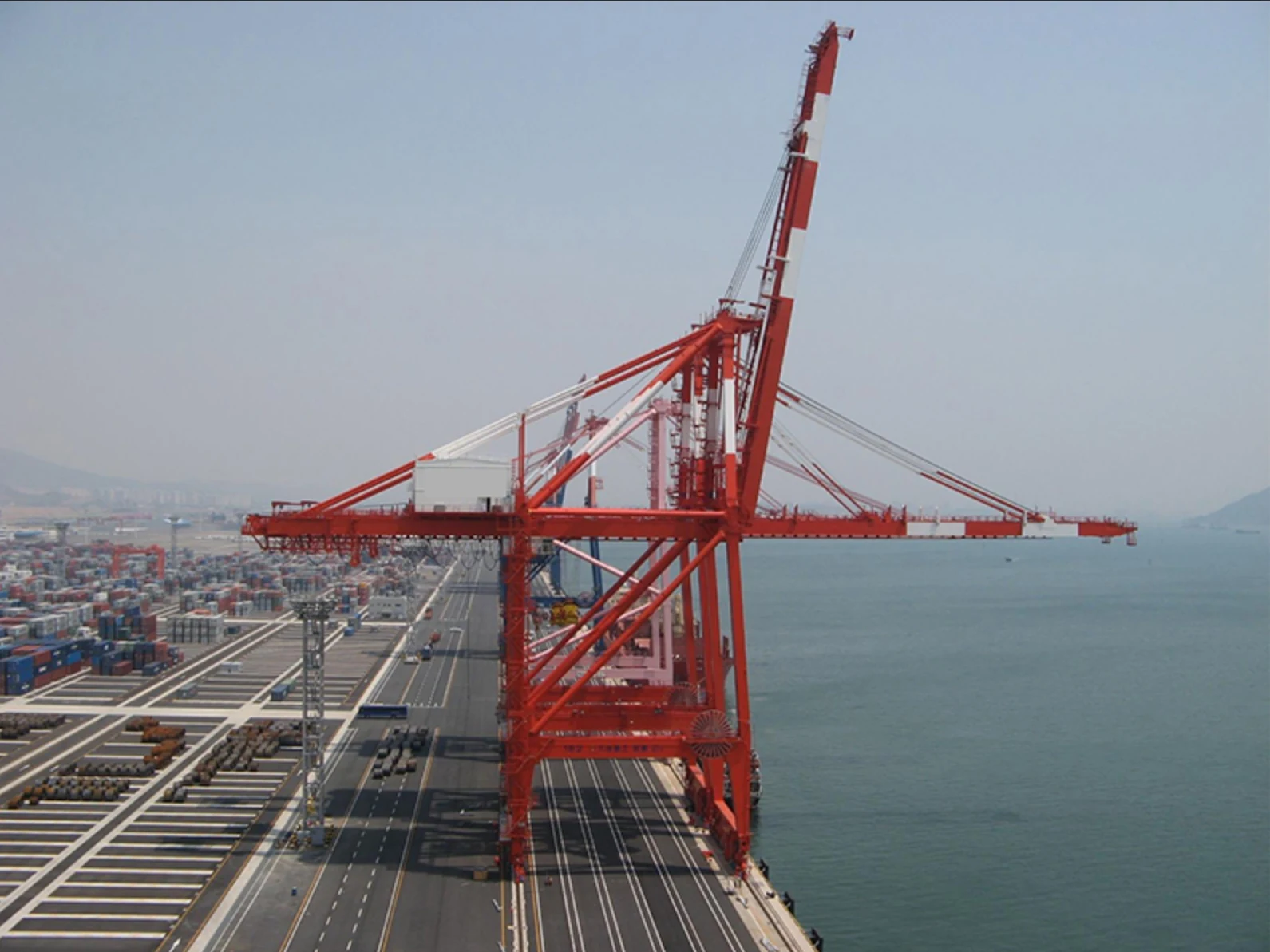
Lift and move vessels through boatyards and marinas.
Explore Marine Travel Lifts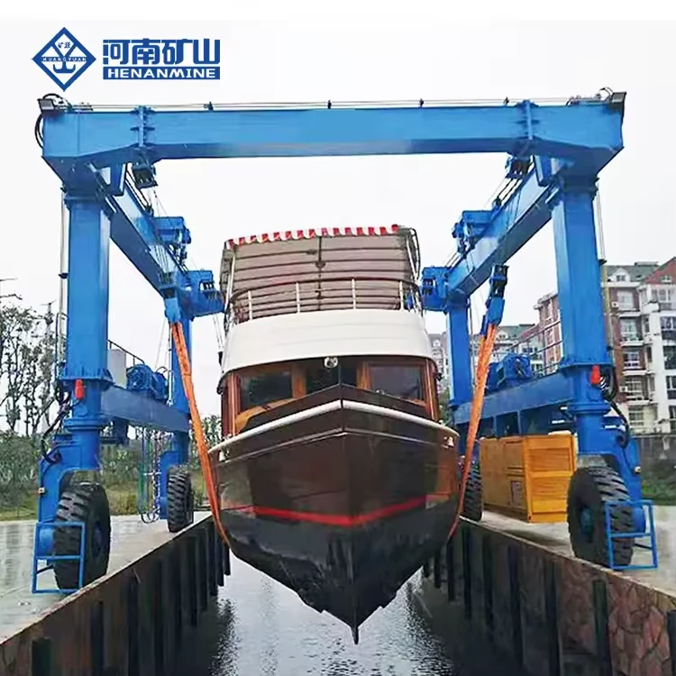
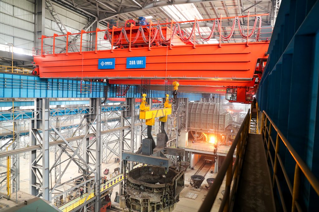
Ladle, slab, scrap and coil handling across steel production.
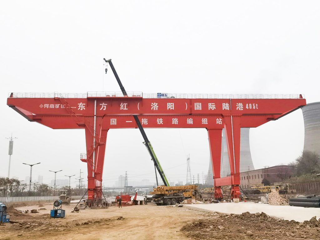
Container stacking and cargo transfers across terminals and rail.
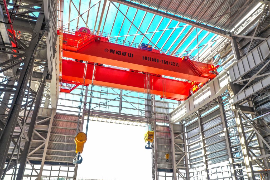
Turbine installation, powerhouse maintenance and wind equipment assembly.
Controlled component transfer and positioning for precision assembly.
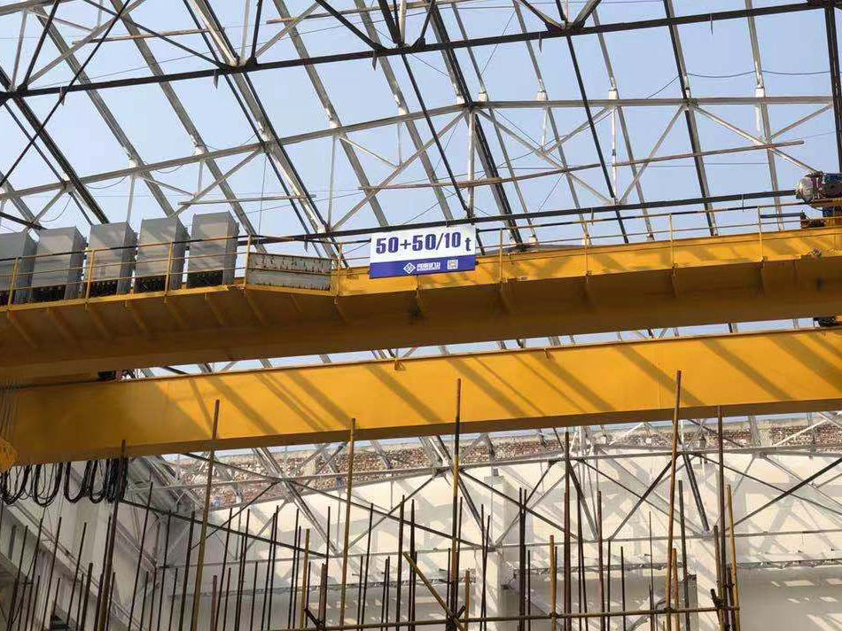
Heavy fabrication, production lifting and factory crane automation.
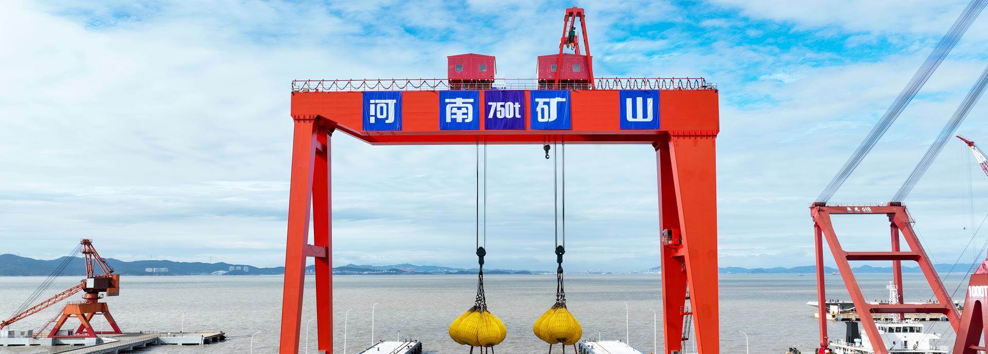
Process lifting for smelters, carbon blocks and anode materials.
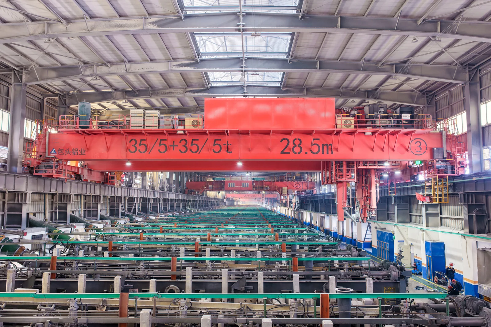
Clean lifting and classified protection for sensitive process areas.
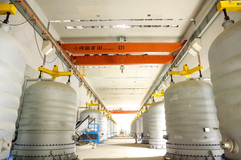
Bridge fabrication, metro construction and ship block assembly.
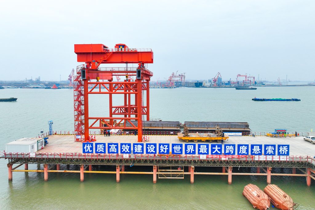
Automated storage and retrieval for plates, cables and bins.
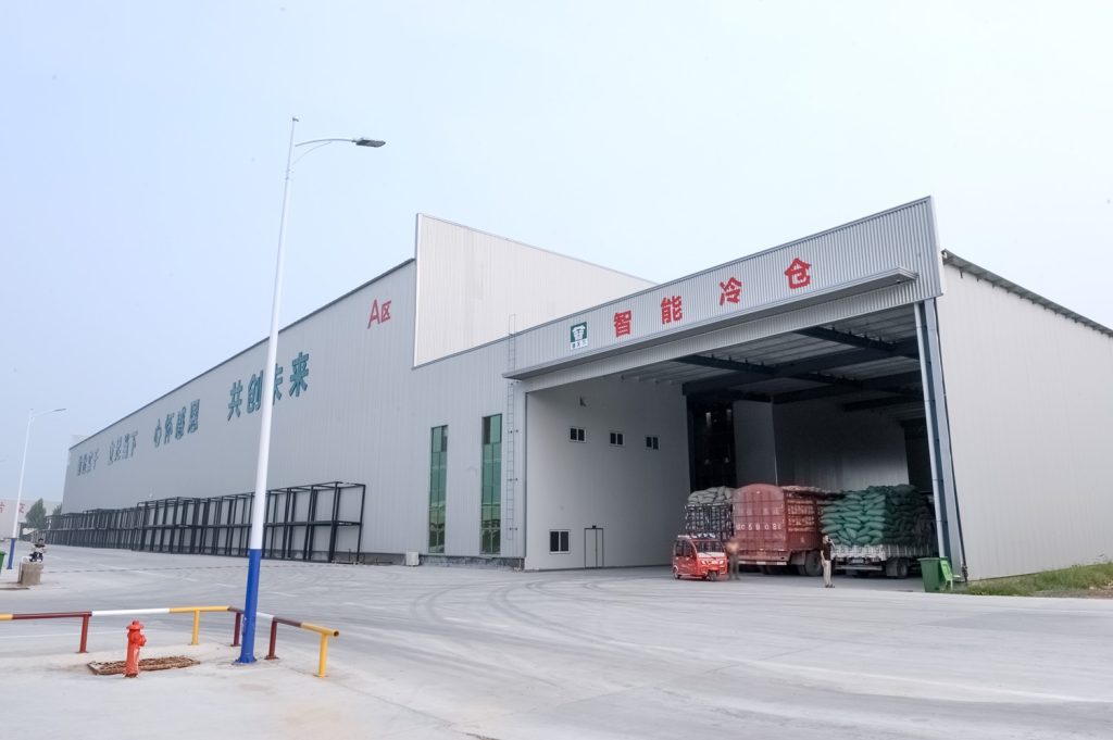
Follow project dispatches, crane engineering and factory acceptance.
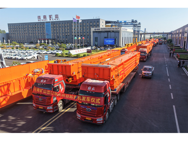
Dispatch, installation and equipment in service
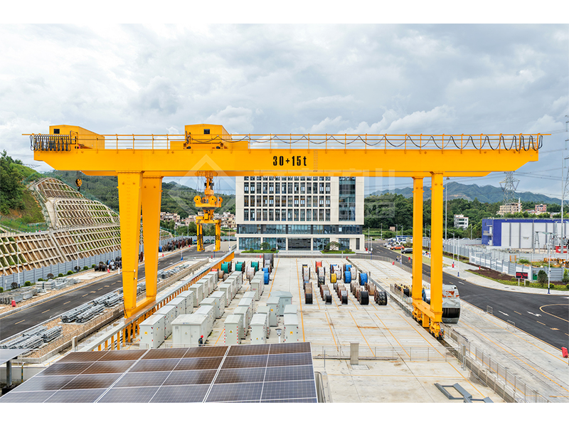
Crane configurations and handling technology
Factory inspections, acceptance and test programmes

Company developments, people and community programmes
Use this to calculate how an offset centre of gravity divides a rigid load’s vertical weight between two lifting points.
Set A as the left reference and B as the second lifting point. Both reactions must act vertically in this model.
Enter the point spacing and the CG position from A. The CG must lie within the interval from A to B.
Read the vertical force and percentage at each lifting point. Do not assume equal sharing unless the CG is at the midpoint.
Mass 10,000 kg; point spacing 4 m; CG 1.5 m from A toward B.
Point A carries 62.5%, or 61.2916 kN. Point B carries 37.5%, or 36.7749 kN. The point closer to the CG carries more vertical load.
The two vertical reactions sum to the static weight of the entered mass.
The percentage outputs express load sharing, while kN outputs express vertical forces at the lifting points.
Inclined sling tension is not the same as the reported vertical reaction; the sling angle must be considered separately.
Using the distance from the load’s outside edge instead of the distance from point A, or treating the two points as equally loaded despite an offset CG.
Reaction A = W × (spacing − CG distance) / spacing
Reaction B = W × CG distance / spacing
The other point has zero calculated vertical reaction. The tool reports this and flags the need to check stability and the actual lifting arrangement.
It can show ideal static vertical shares for a rigid two-support model, but it does not plan a tandem lift or account for crane motion, flexibility and dynamic redistribution.