
Set one wheel pair
Enter the two downward wheel forces and their fixed spacing. This tool supports a spacing no greater than the beam span.
Bridge cranes for workshops and production lines.
Explore Overhead Cranes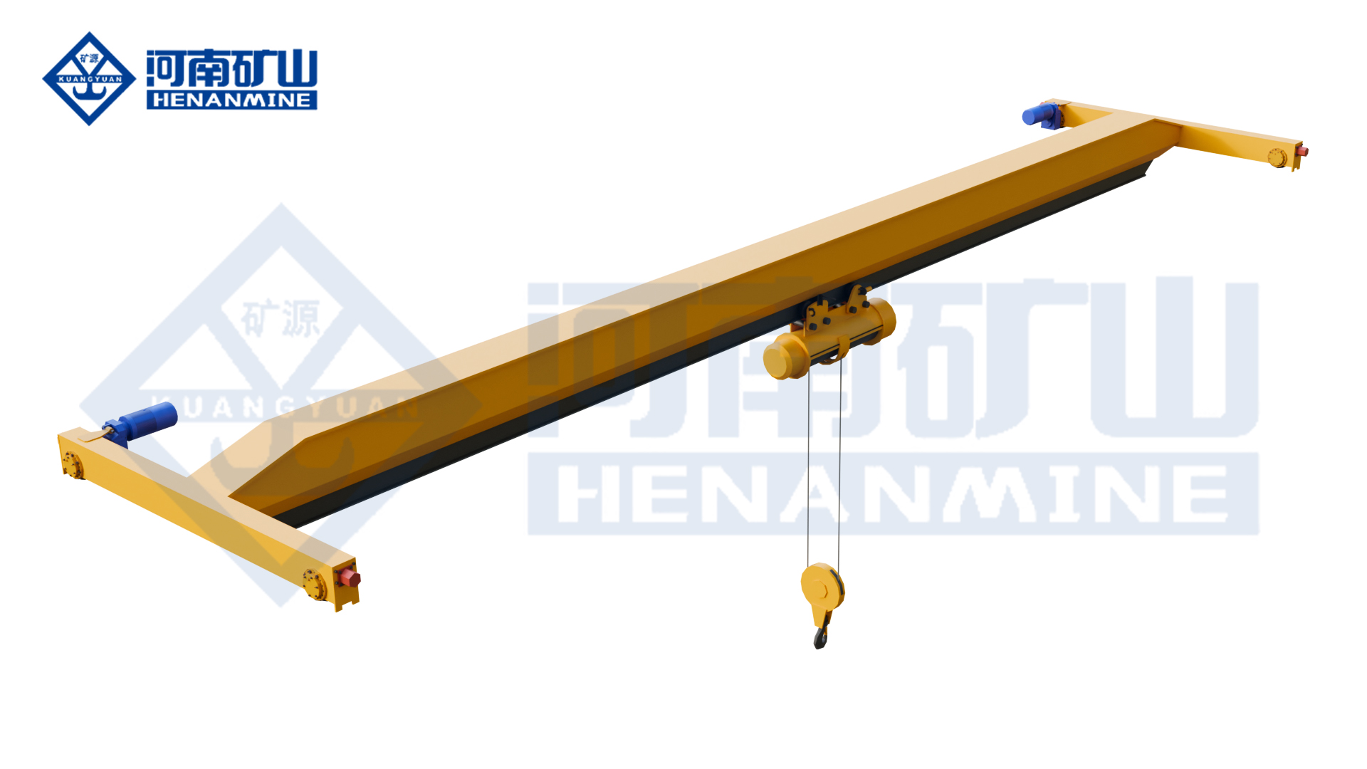
Ground-supported lifting for yards and construction.
Explore Gantry Cranes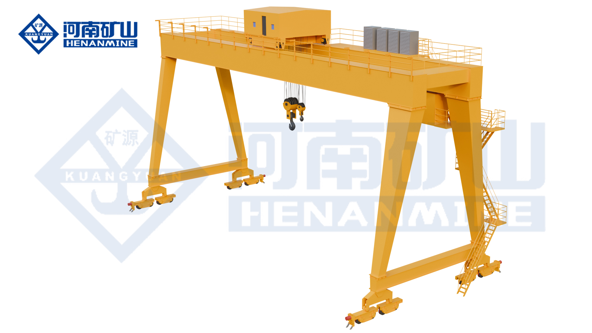
Wire rope and chain hoists for lifting points and cranes.
Explore Electric Hoists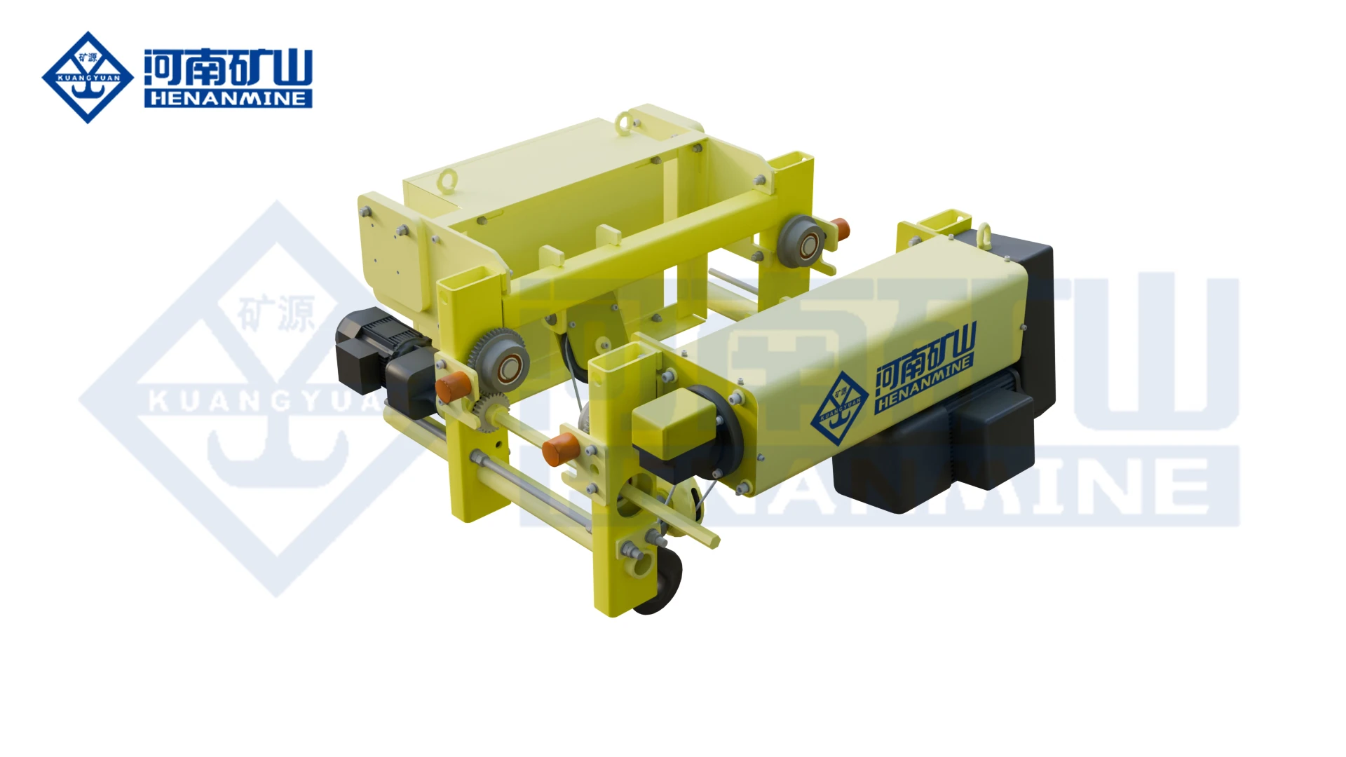
Wire rope lifting and pulling with a powered drum.
Explore Electric Winches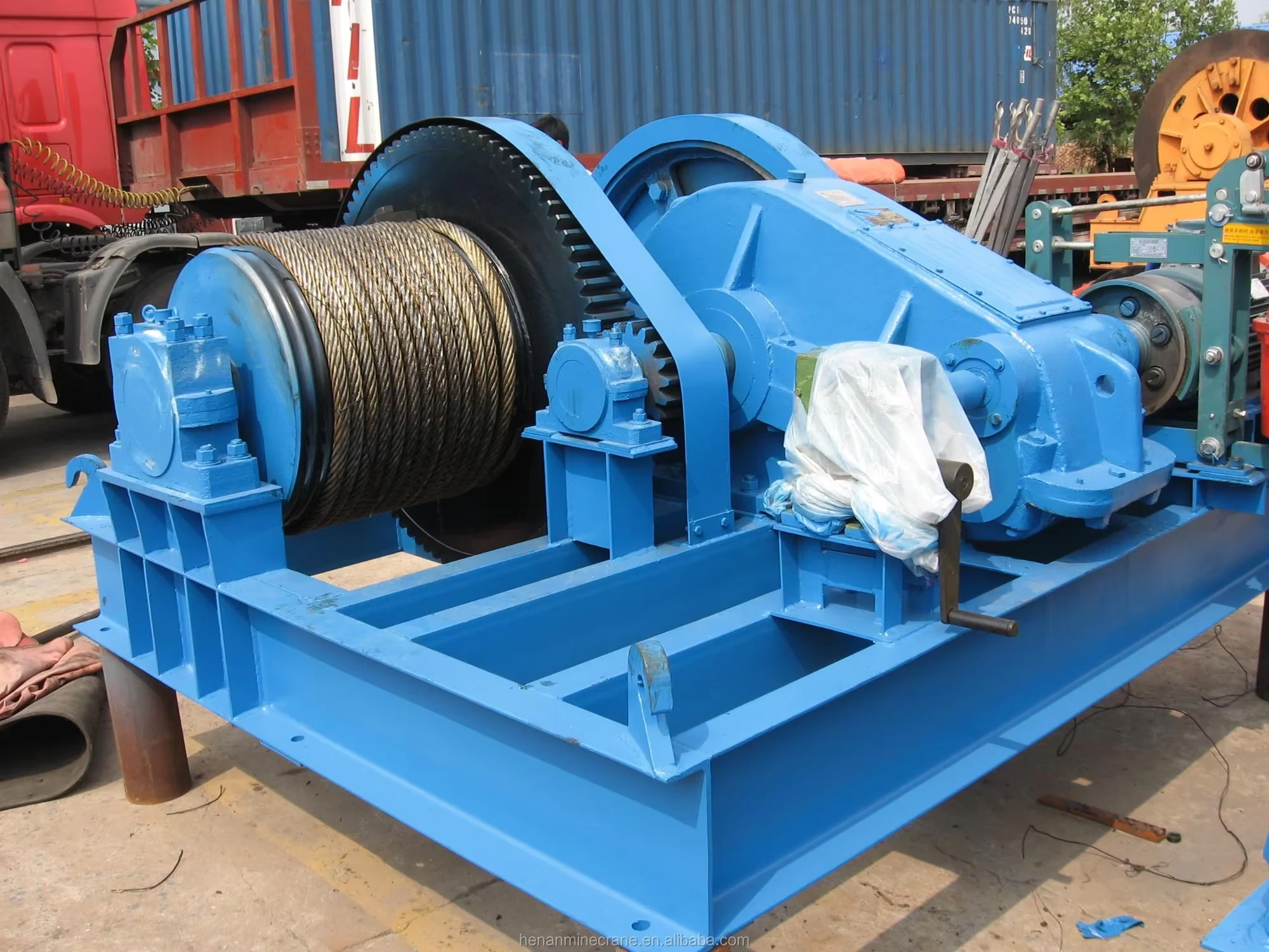
Grab buckets, magnets and hooks for your load.
Explore Lifting Attachments & Grabs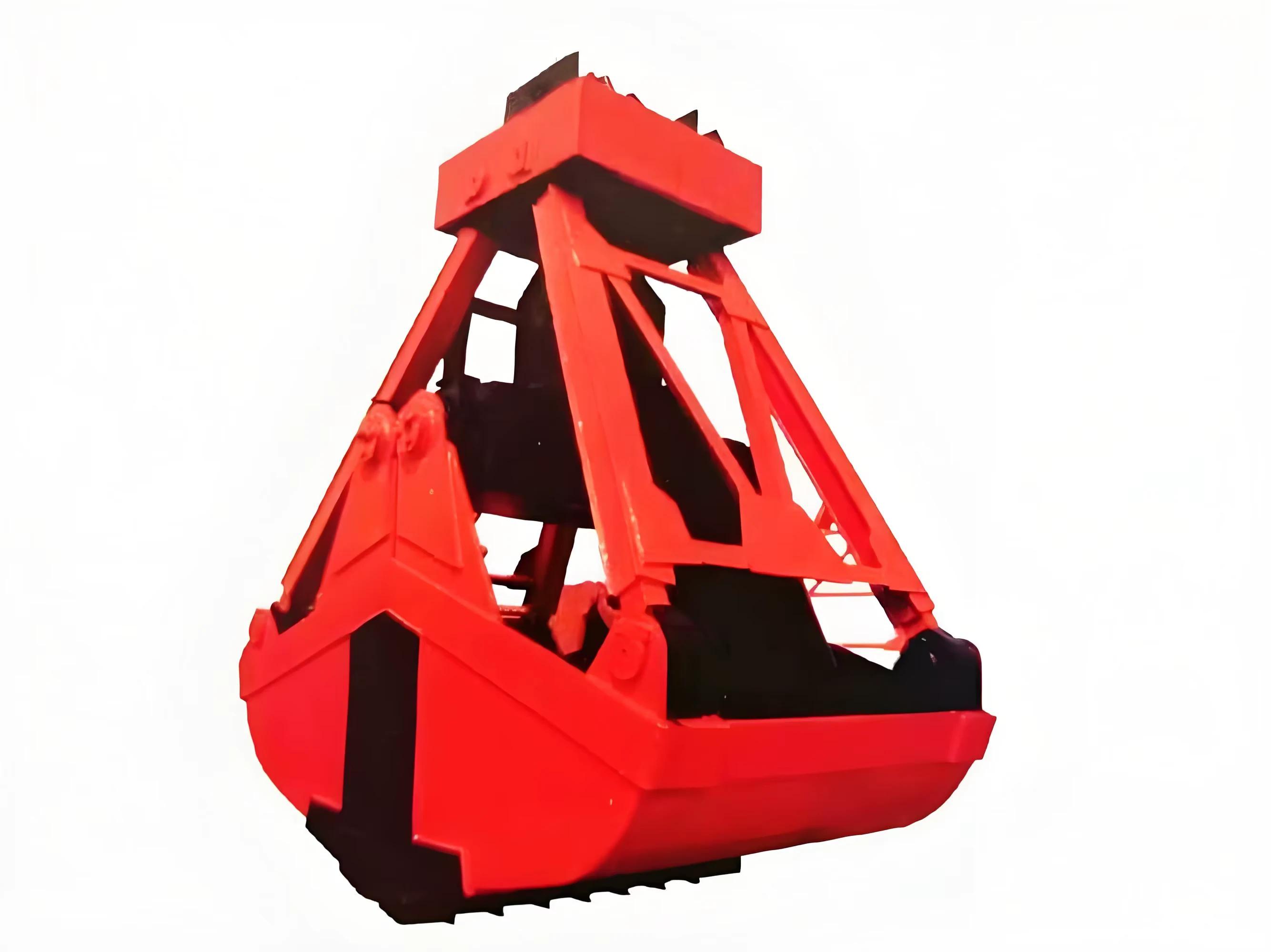
Mobile handling for containers, precast and yard loads.
Explore Rubber-Tired Gantry Cranes & Straddle Carriers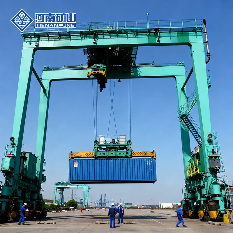
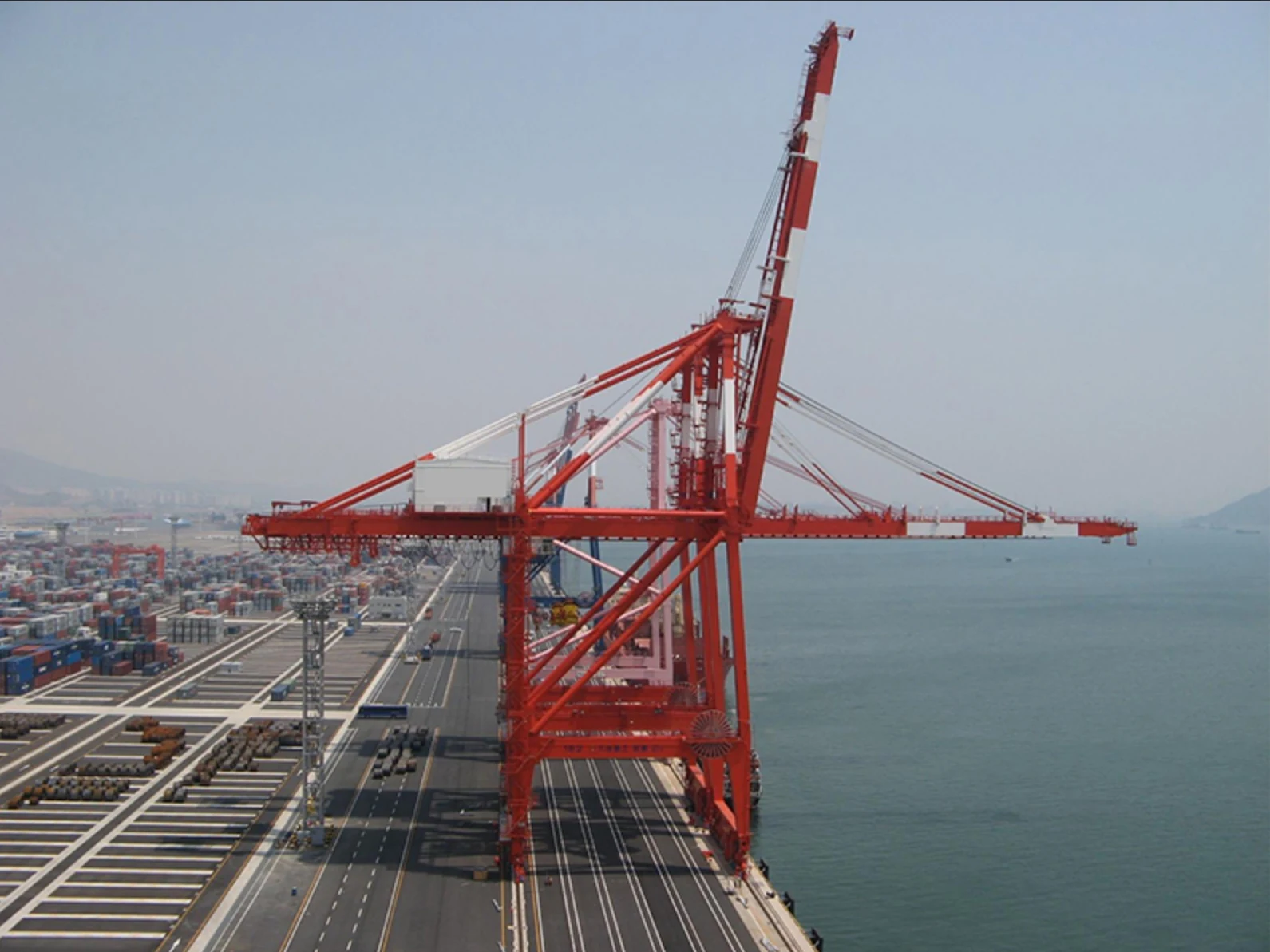
Lift and move vessels through boatyards and marinas.
Explore Marine Travel Lifts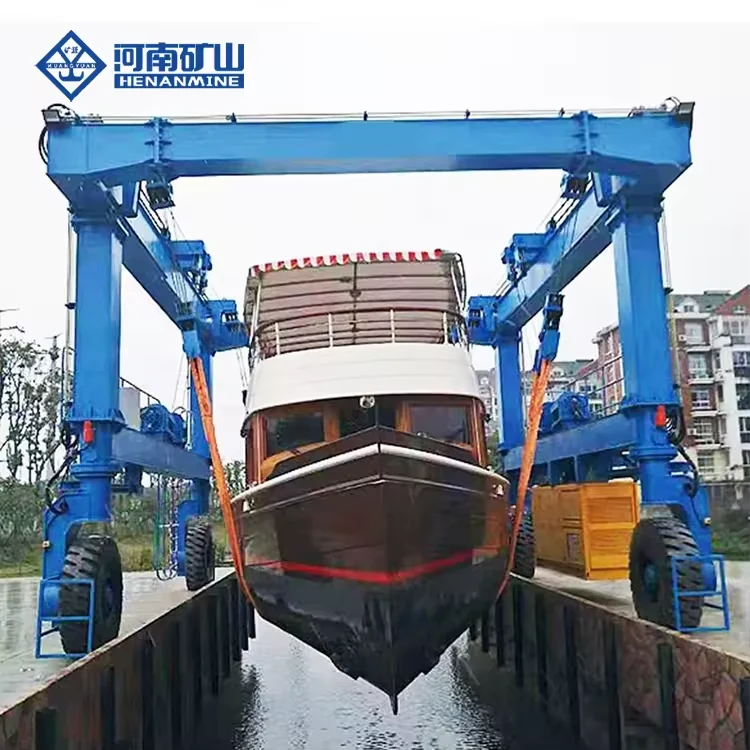
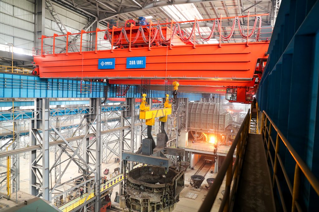
Ladle, slab, scrap and coil handling across steel production.
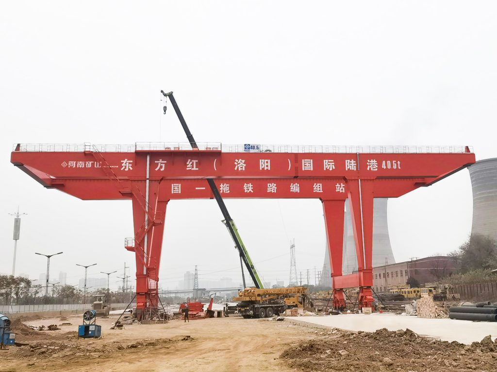
Container stacking and cargo transfers across terminals and rail.
Turbine installation, powerhouse maintenance and wind equipment assembly.
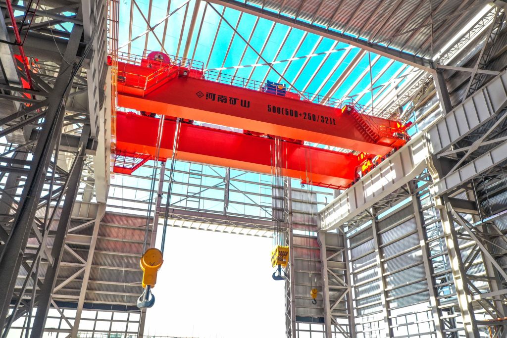
Controlled component transfer and positioning for precision assembly.
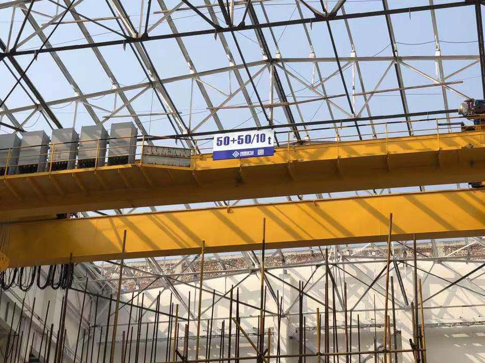
Heavy fabrication, production lifting and factory crane automation.
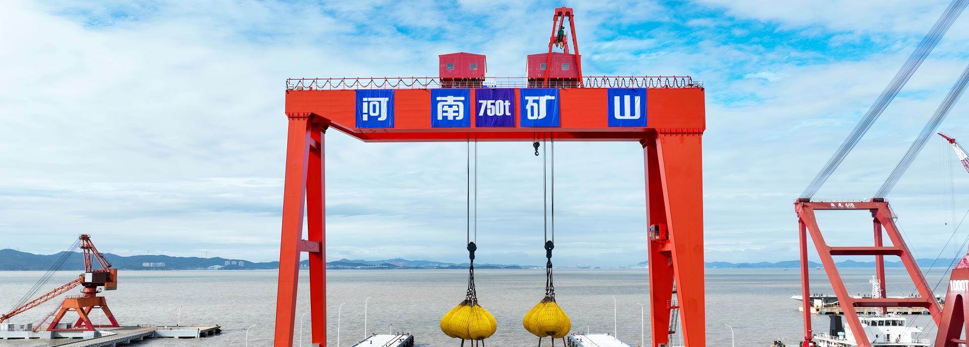
Process lifting for smelters, carbon blocks and anode materials.
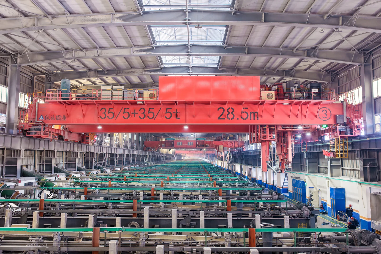
Clean lifting and classified protection for sensitive process areas.
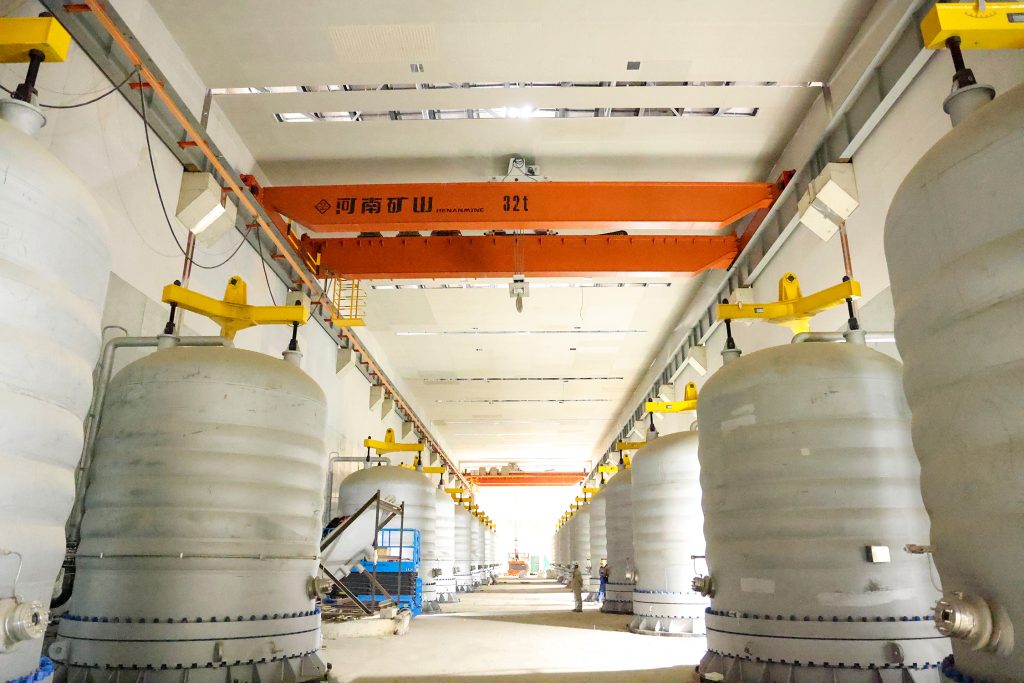
Bridge fabrication, metro construction and ship block assembly.
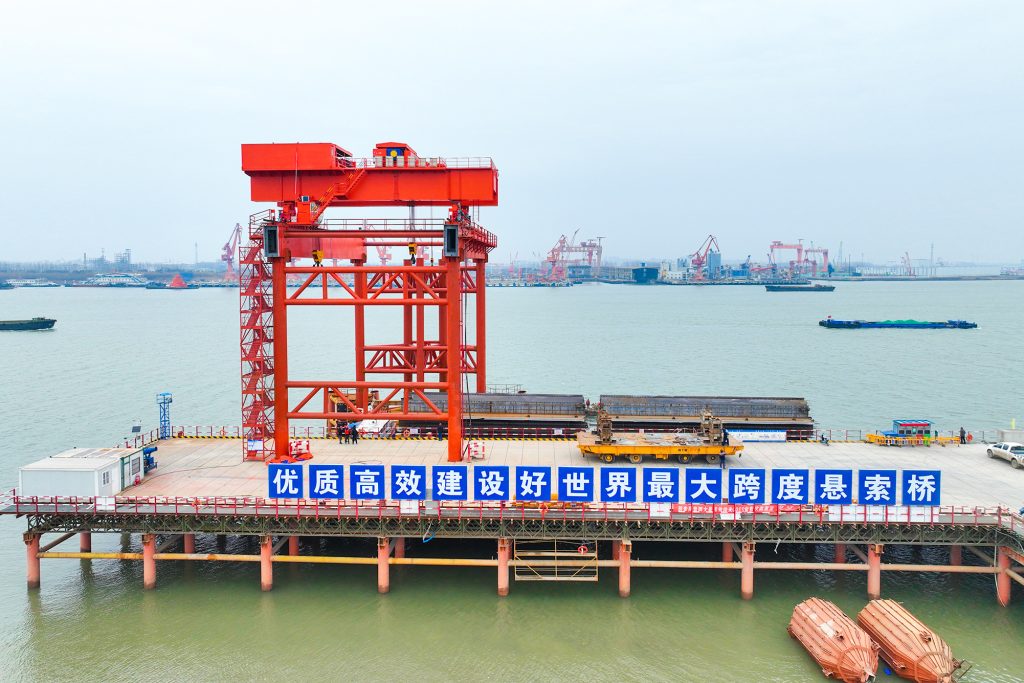
Automated storage and retrieval for plates, cables and bins.
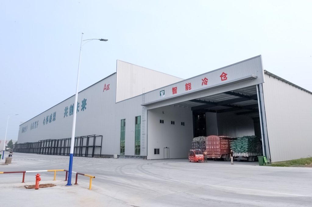
Follow project dispatches, crane engineering and factory acceptance.
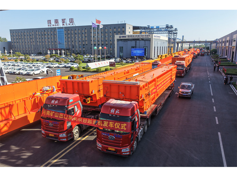
Dispatch, installation and equipment in service
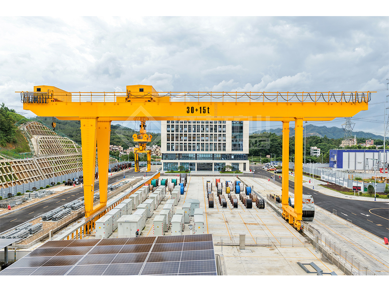
Crane configurations and handling technology
Factory inspections, acceptance and test programmes

Company developments, people and community programmes
Use this to explore how a fixed pair of wheel forces changes the actions on a simple beam as the wheels enter, cross and leave the span.
Enter the two downward wheel forces and their fixed spacing. This tool supports a spacing no greater than the beam span.
The first wheel is at s and the second at s + spacing. A negative s means the first wheel has not yet entered the span while the second may already be on it.
The program moves the pair through sampled travel positions, then reports maximum moment, reactions and internal shear with their corresponding first-wheel coordinates.
Span 10 m; P1 = 50 kN; P2 = 50 kN; wheel spacing 2 m.
The sampled maximum sagging moment is 202.5 kN·m. One maximum occurs with the first wheel at 3.5 m and the critical section at 5.5 m. Maximum support reactions are 90 kN; the sampled internal shear maximum is 89.95 kN.
The plotted curve shows the maximum bending moment at each wheel-pair travel position; it is not beam deflection or the bending diagram for one position.
Moment, reaction and shear maxima can occur at different wheel positions. Use the location reported with each result.
The envelope uses 2,401 uniform travel positions plus exact entry and exit positions. Internal-action maxima are numerical approximations.
Treating the 100 kN total of two wheels as one centred force, or using the crane span as the wheel spacing along the runway.
For wheels on the span: RA = Σ[P × (L − x) / L]; RB = Σ[P × x / L]
M(z) = RA × z − Σ[P × max(z − x, 0)]
Maximum positive moment occurs at a wheel or a support for each sampled travel position.
A force placed exactly at a support contributes to the reaction but not the internal shear just inside the span. Nearby sampled positions approach the limiting internal value.
No. It includes only the two entered downward forces on a simple span. Uniform weight, dynamic factors, lateral effects and design combinations are separate.