
Confirm the narrow model conditions
Use only a straight prismatic doubly symmetric I beam with uniform bending moment. The moment-gradient factor is fixed at C1 = 1.
Bridge cranes for workshops and production lines.
Explore Overhead Cranes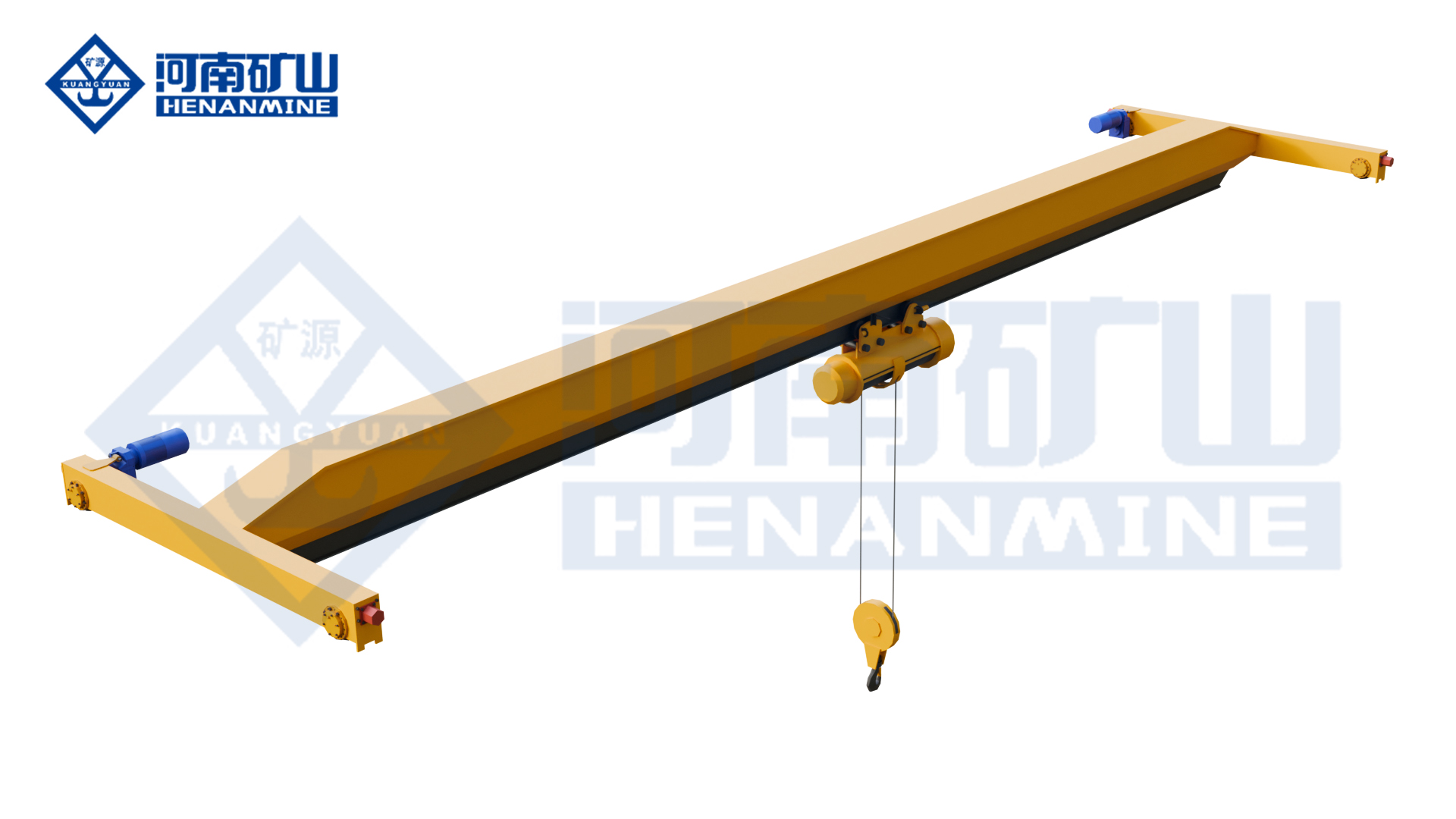
Ground-supported lifting for yards and construction.
Explore Gantry Cranes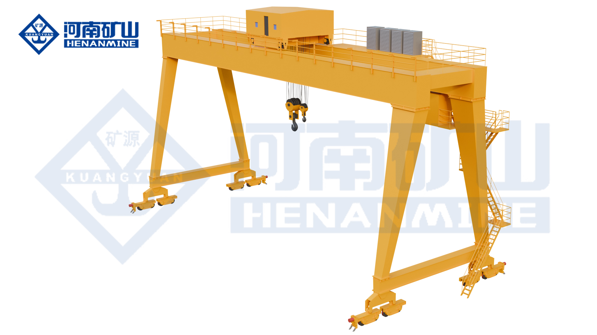
Wire rope and chain hoists for lifting points and cranes.
Explore Electric Hoists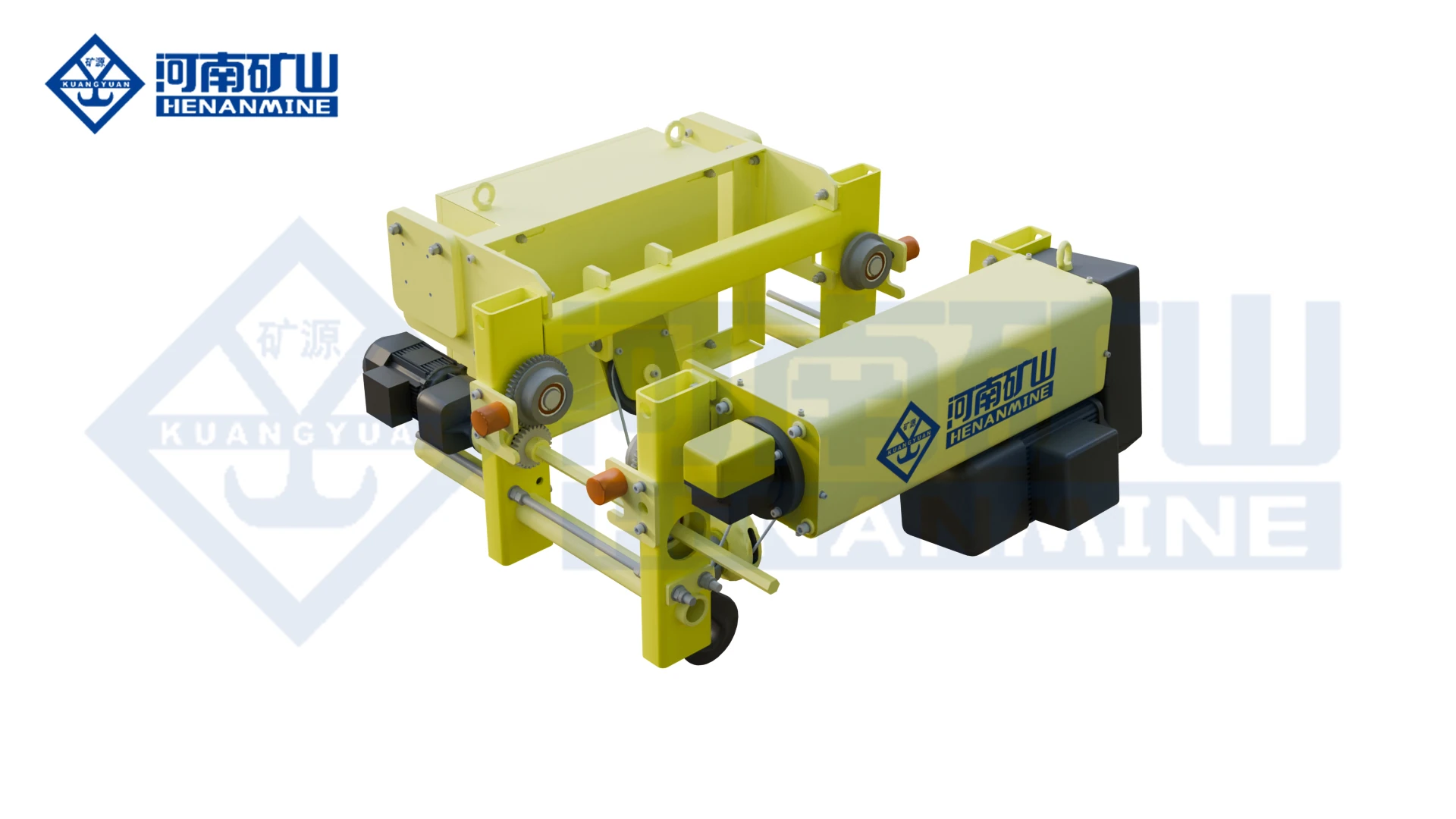
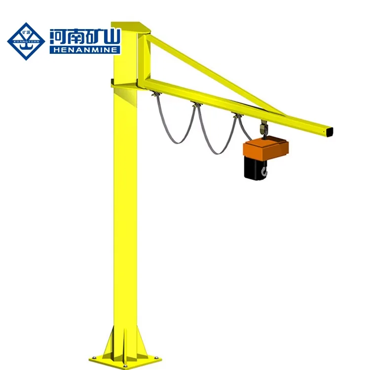
Wire rope lifting and pulling with a powered drum.
Explore Electric Winches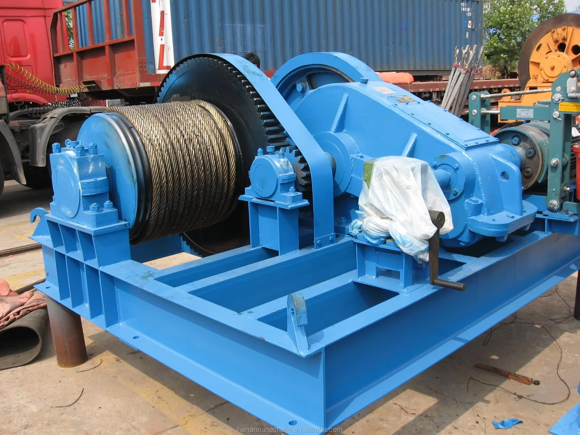
Grab buckets, magnets and hooks for your load.
Explore Lifting Attachments & Grabs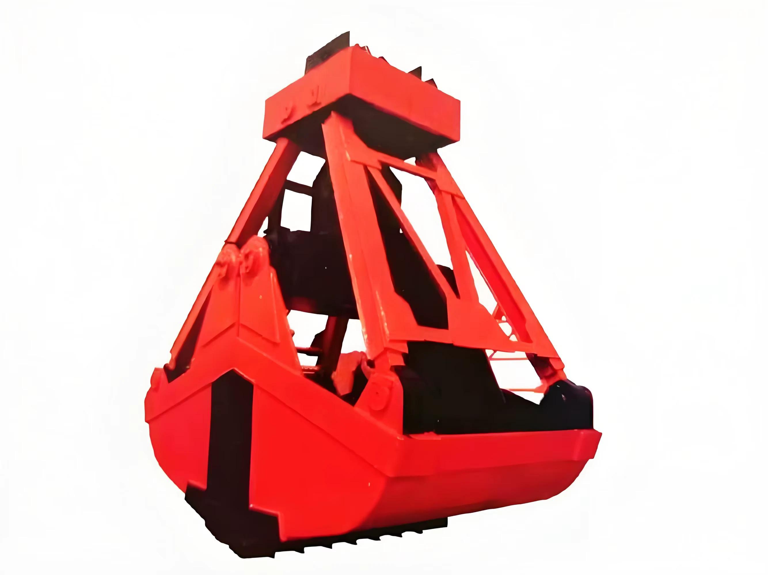
Mobile handling for containers, precast and yard loads.
Explore Rubber-Tired Gantry Cranes & Straddle Carriers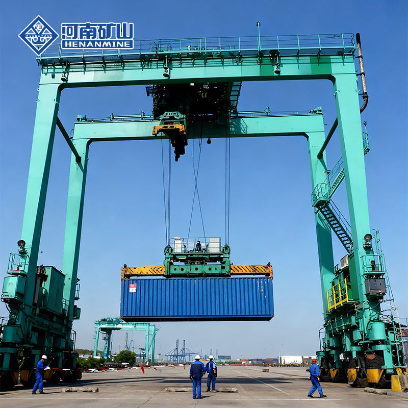
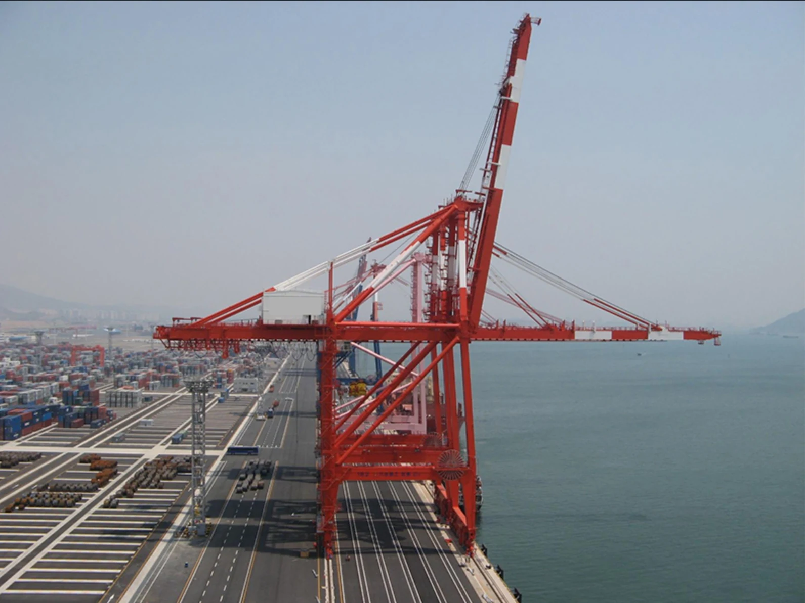
Lift and move vessels through boatyards and marinas.
Explore Marine Travel Lifts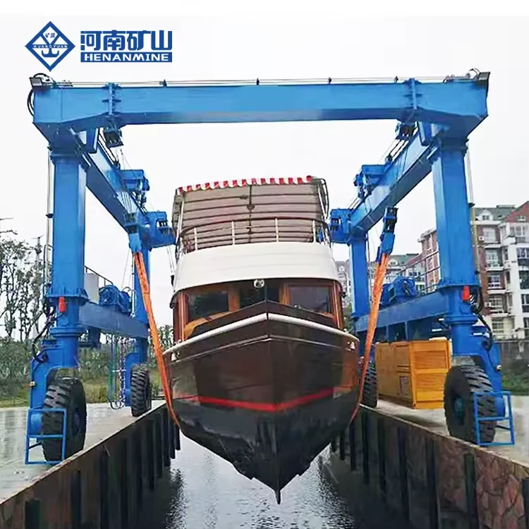
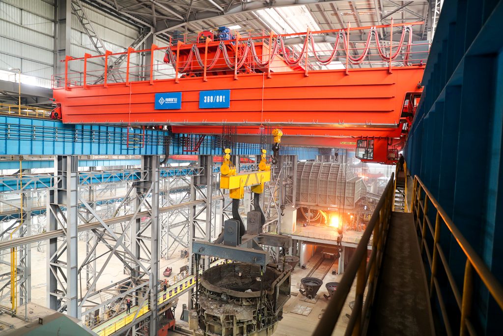
Ladle, slab, scrap and coil handling across steel production.
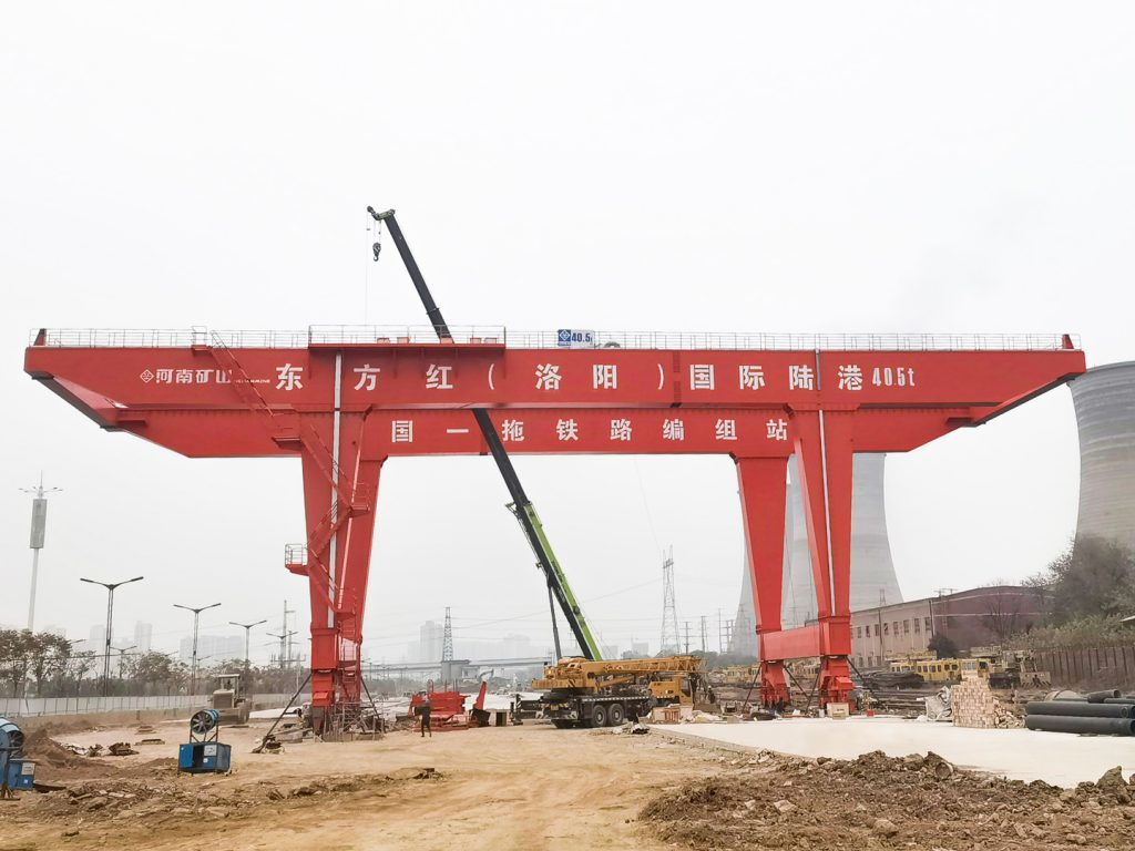
Container stacking and cargo transfers across terminals and rail.
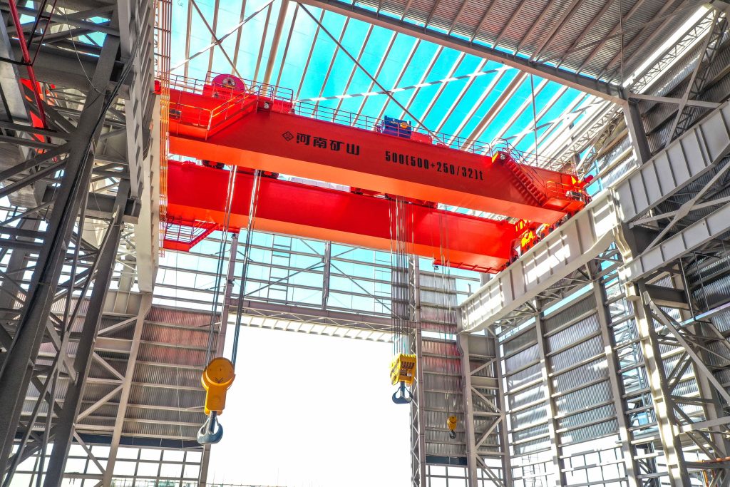
Turbine installation, powerhouse maintenance and wind equipment assembly.
Controlled component transfer and positioning for precision assembly.
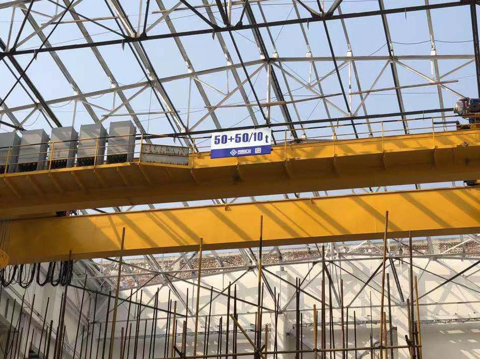
Heavy fabrication, production lifting and factory crane automation.
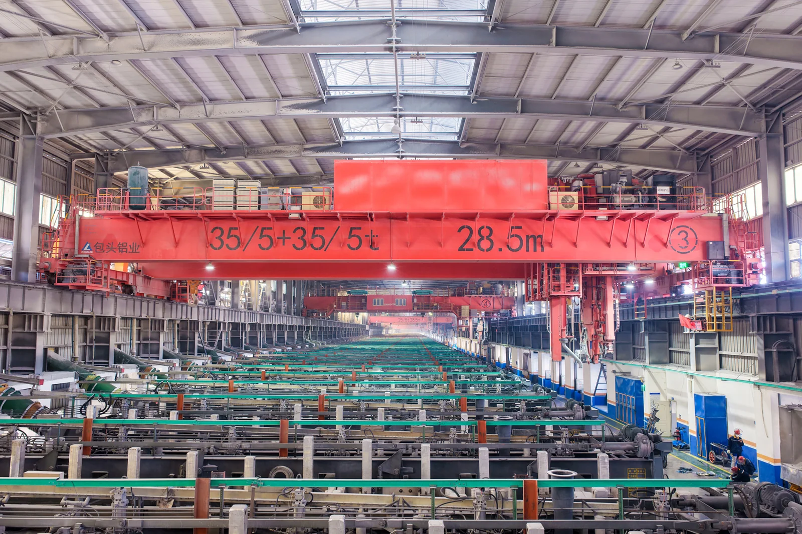
Process lifting for smelters, carbon blocks and anode materials.
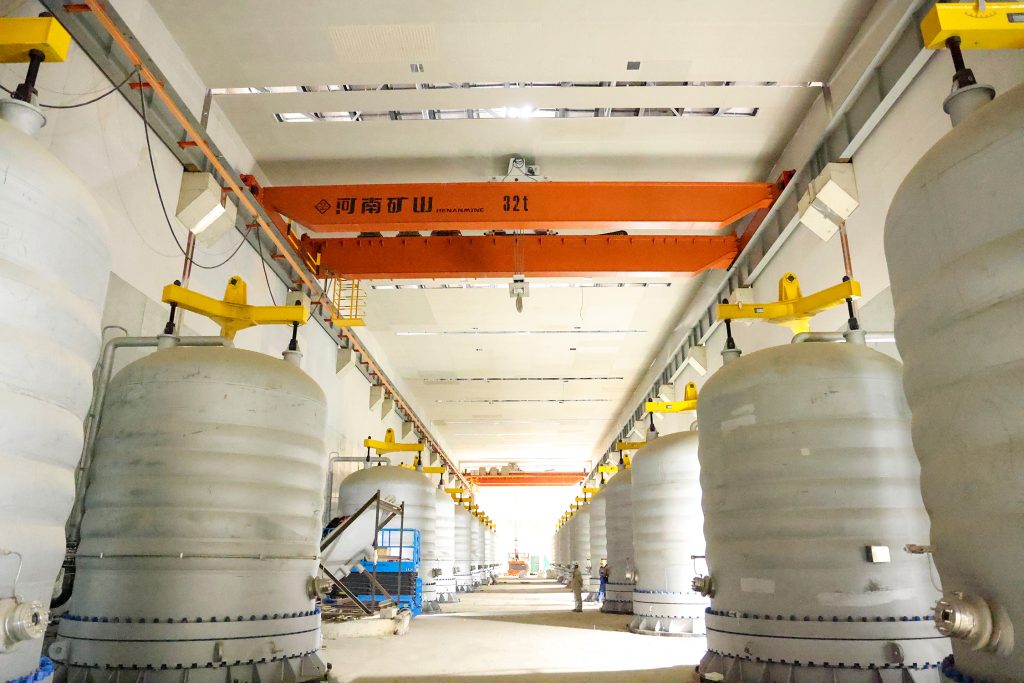
Clean lifting and classified protection for sensitive process areas.
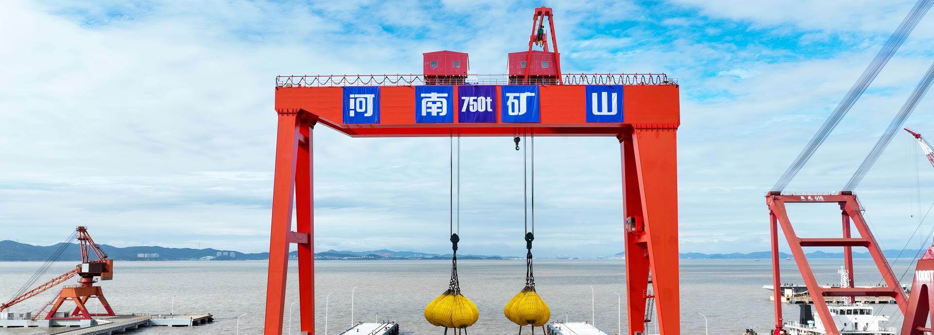
Bridge fabrication, metro construction and ship block assembly.
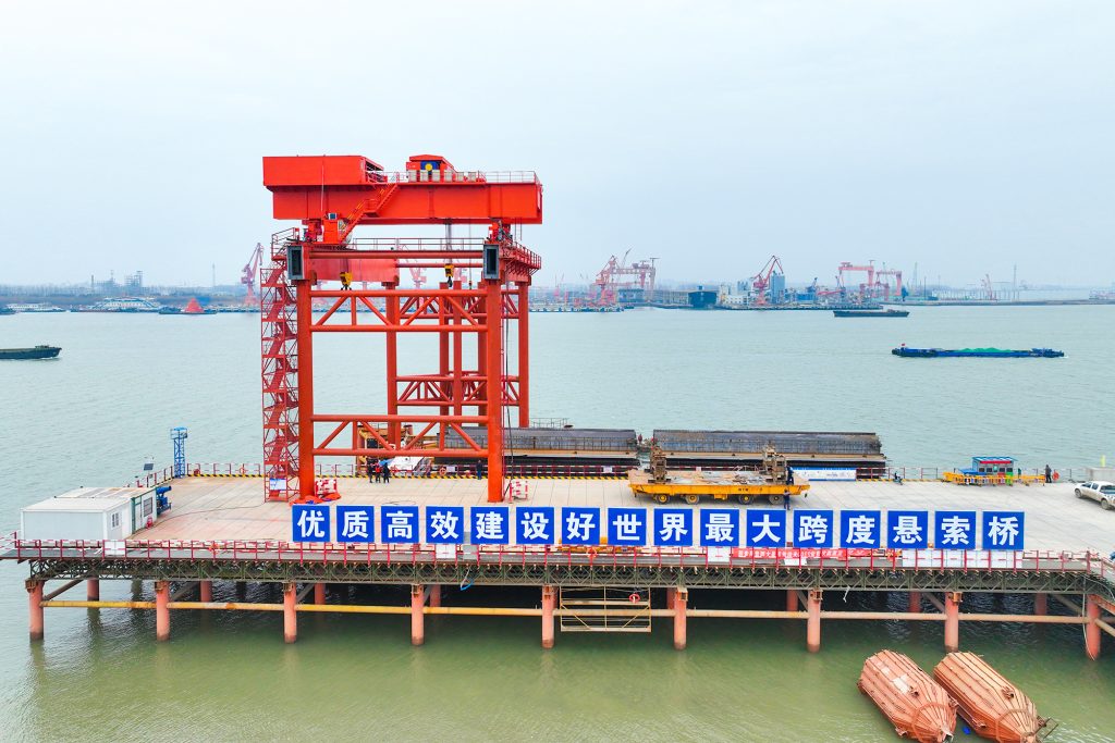
Automated storage and retrieval for plates, cables and bins.
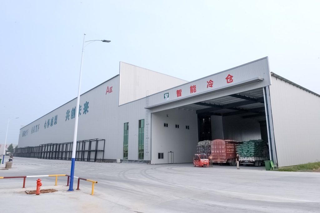
Follow project dispatches, crane engineering and factory acceptance.
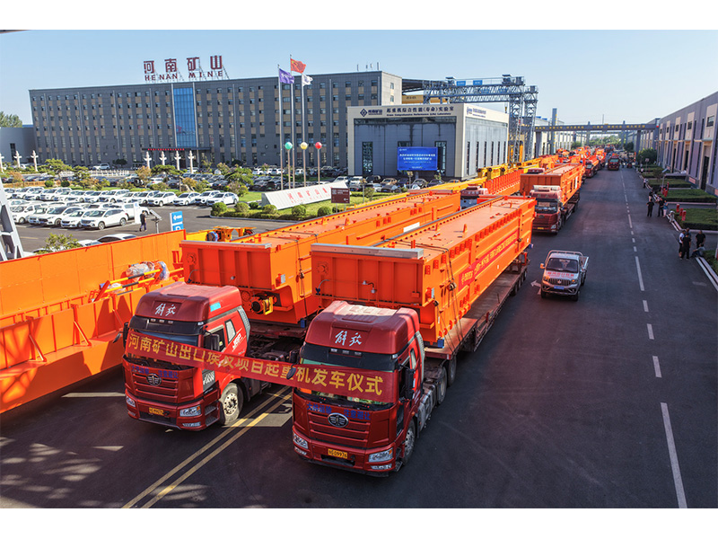
Dispatch, installation and equipment in service
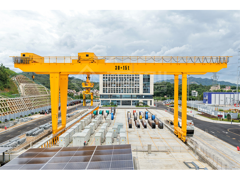
Crane configurations and handling technology
Factory inspections, acceptance and test programmes

Company developments, people and community programmes
Use this to examine the classical elastic lateral–torsional critical moment of an ideal, doubly symmetric I beam under uniform pure major-axis bending.
Use only a straight prismatic doubly symmetric I beam with uniform bending moment. The moment-gradient factor is fixed at C1 = 1.
Use the weak-axis second moment, Saint-Venant J and warping Iw in the displayed units. J is not the polar second moment of area.
Review how unbraced length changes the ideal bifurcation moment. Do not treat Mcr as an allowable working moment or a code design resistance.
E = 200,000 MPa; G = 77,000 MPa; weak-axis Iz = 8,000,000 mm⁴; J = 150,000 mm⁴; Iw = 1,000,000,000,000 mm⁶; L = 6 m.
The ideal elastic critical moment Mcr is approximately 170.640 kN·m for the stated model with C1 = 1. This is not a rated or permissible working moment.
Mcr is the elastic bifurcation value for the stated support and loading assumptions.
The unbraced length is the segment with no intermediate restraint; it need not be the complete fabricated member length.
Yielding, residual stress, initial imperfections, local buckling and load-height effects are excluded. A design-resistance calculation needs an appropriate design method beyond this result.
Substituting the polar second moment for Saint-Venant J, or applying this uniform-moment equation to an arbitrary crane girder with unspecified restraints and load height.
Mcr = (π / L) × √[E × Iz × G × J + π² × E² × Iz × Iw / L²]
Use N and mm consistently; divide N·mm by 1,000,000 for kN·m.
No. Mcr is not code resistance or an allowable moment. Imperfections, yielding, relevant factors and other failure modes need the appropriate separate design checks.
Not in this tool. It fixes C1 = 1 and ideal end fork supports with free warping. Other restraint and loading conditions need a different model.