
Define the contact rectangle
Keep length along x and width along y consistent with the diagram and the applied moments.
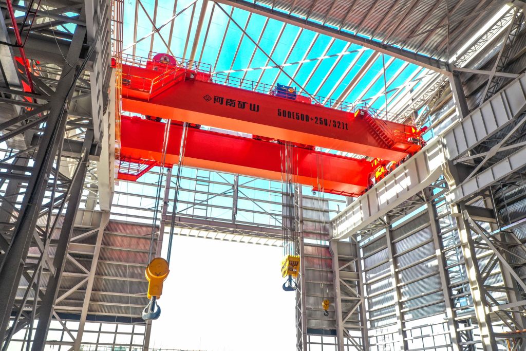
Bridge cranes for workshops and production lines.
Explore Overhead Cranes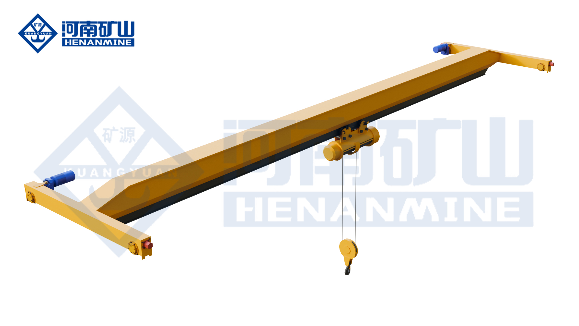
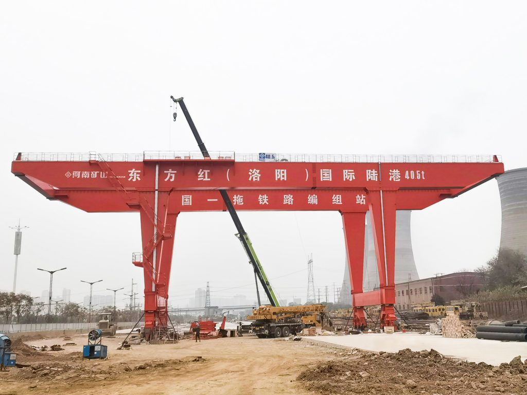
Ground-supported lifting for yards and construction.
Explore Gantry Cranes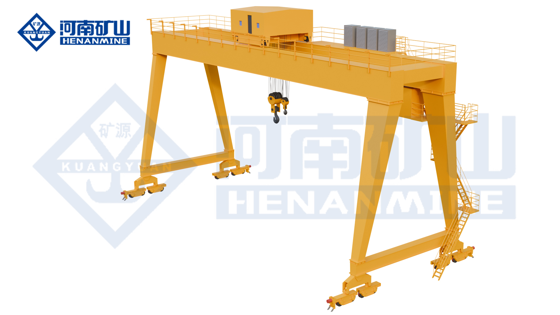
Wire rope and chain hoists for lifting points and cranes.
Explore Electric Hoists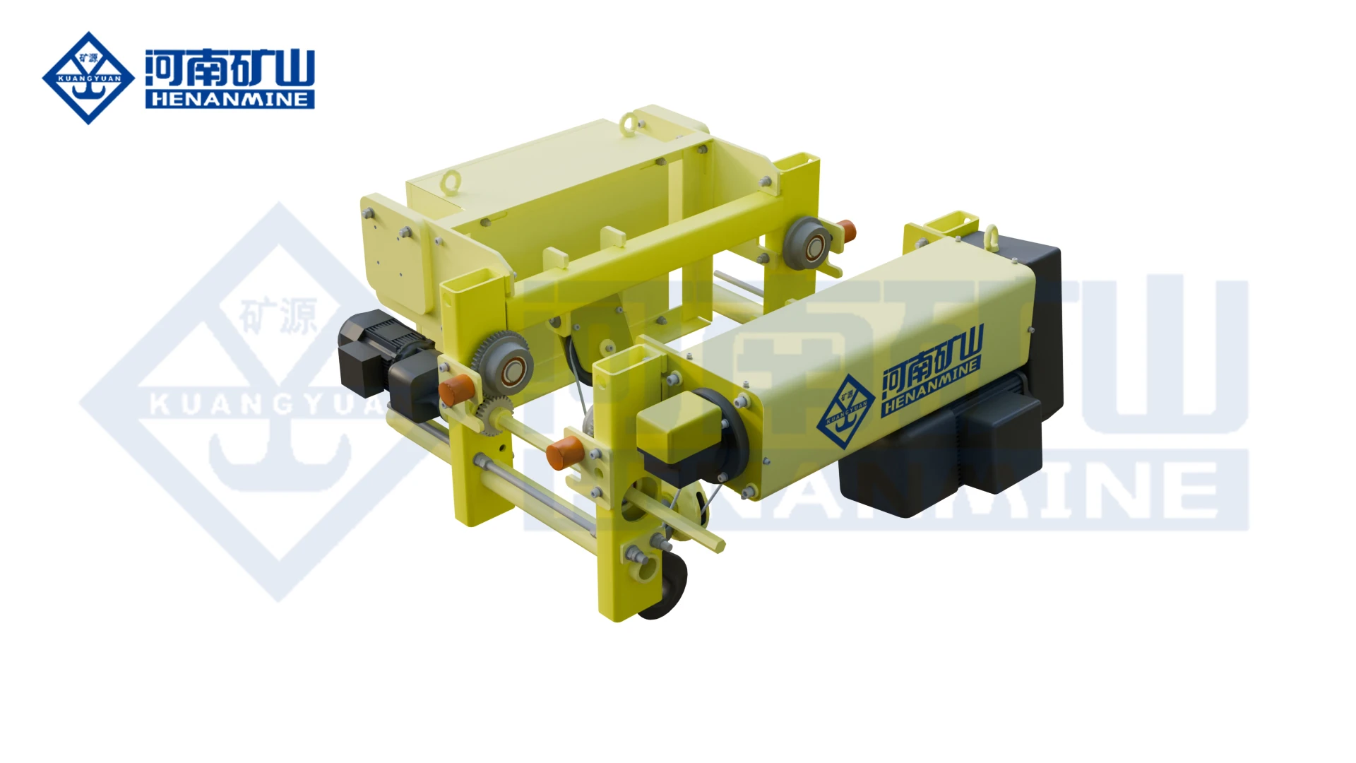
Wire rope lifting and pulling with a powered drum.
Explore Electric Winches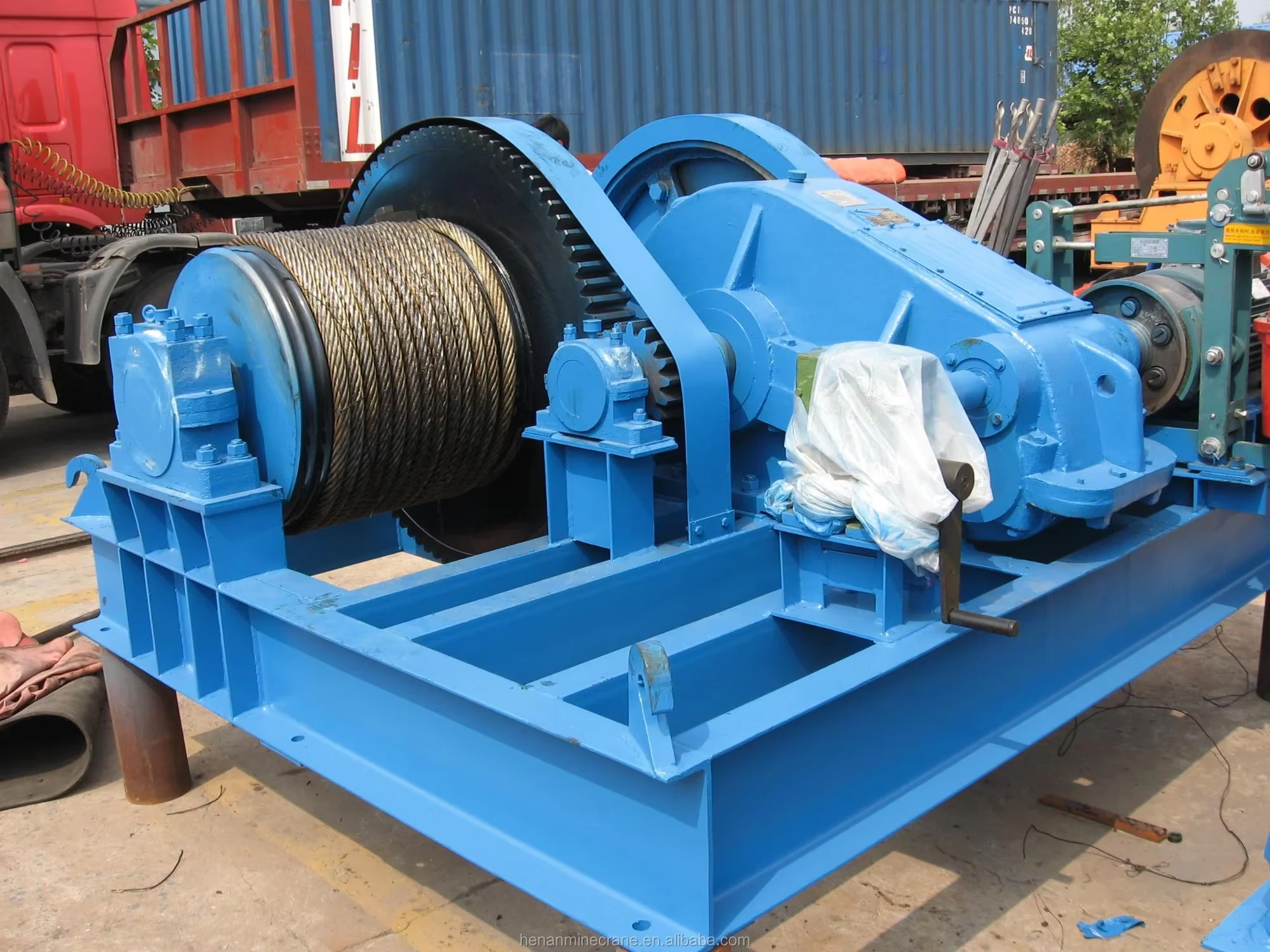
Grab buckets, magnets and hooks for your load.
Explore Lifting Attachments & Grabs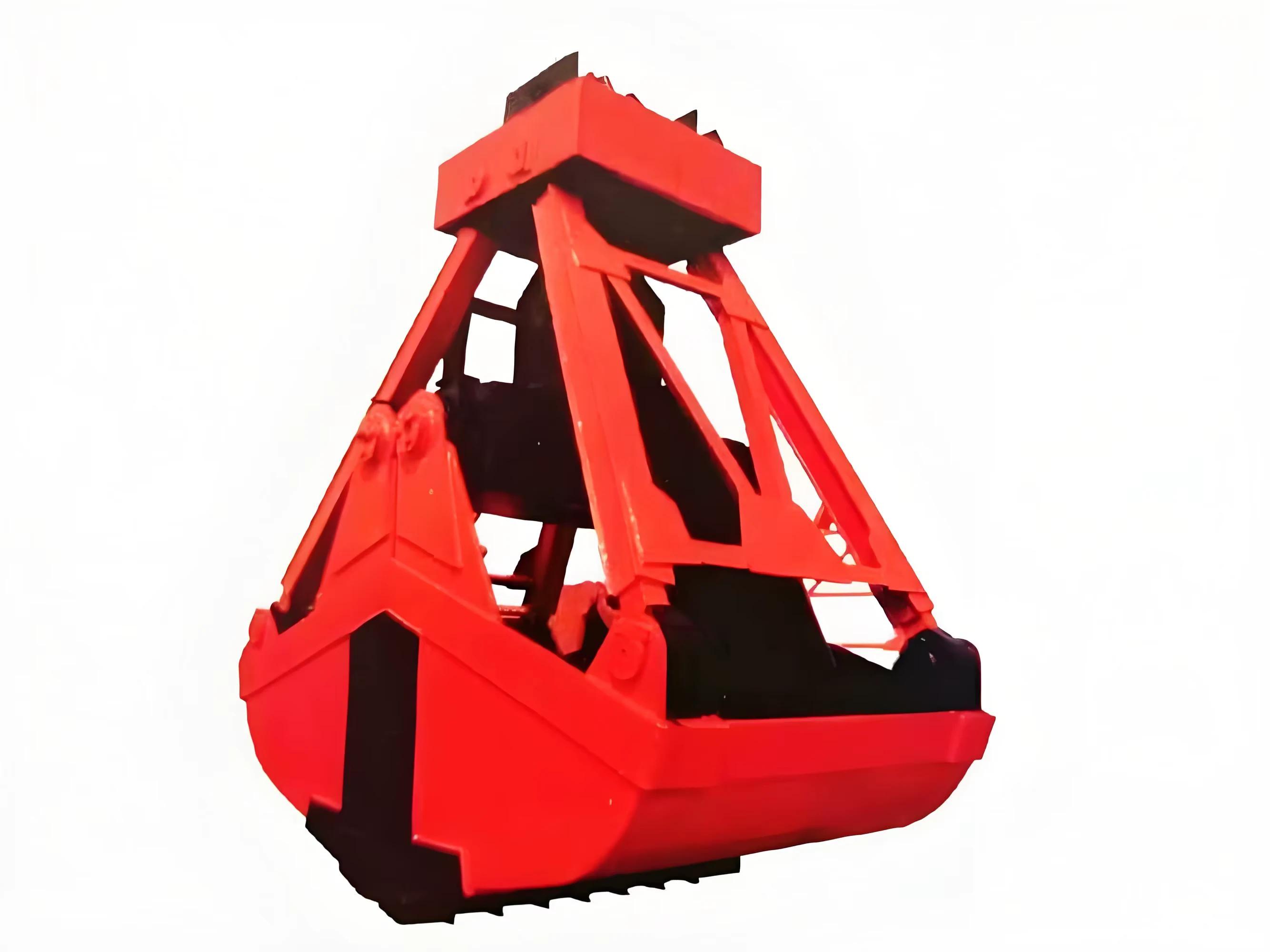
Mobile handling for containers, precast and yard loads.
Explore Rubber-Tired Gantry Cranes & Straddle Carriers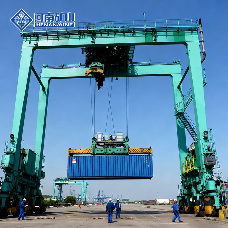
Lift and move vessels through boatyards and marinas.
Explore Marine Travel Lifts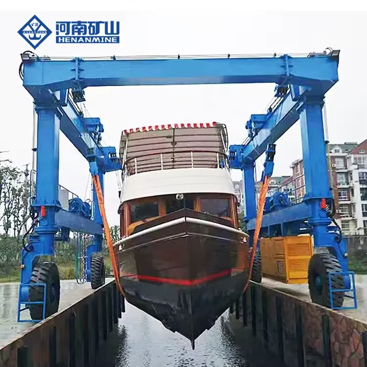
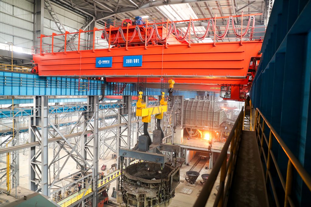
Ladle, slab, scrap and coil handling across steel production.
Container stacking and cargo transfers across terminals and rail.
Turbine installation, powerhouse maintenance and wind equipment assembly.
Controlled component transfer and positioning for precision assembly.
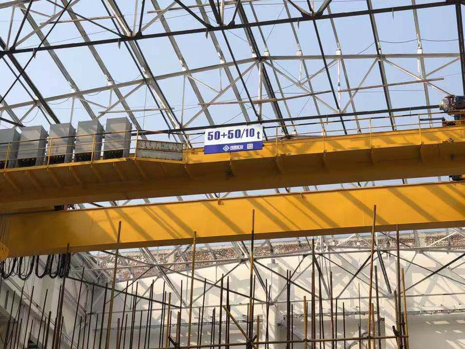
Heavy fabrication, production lifting and factory crane automation.
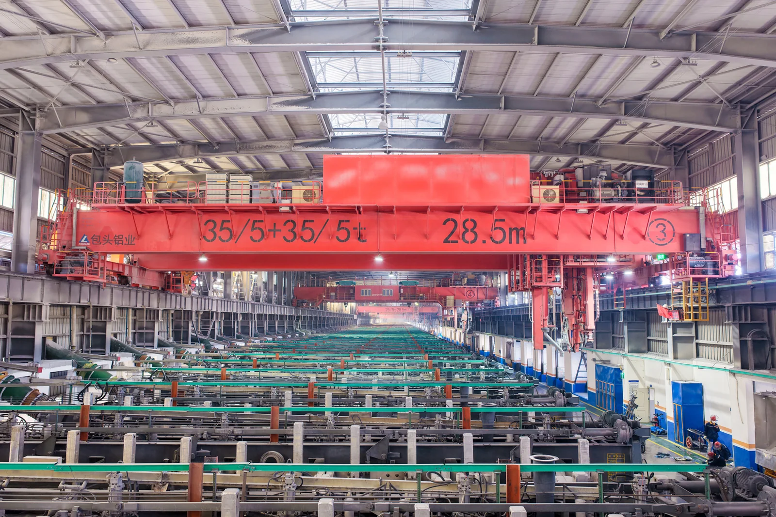
Process lifting for smelters, carbon blocks and anode materials.
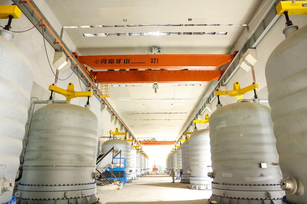
Clean lifting and classified protection for sensitive process areas.
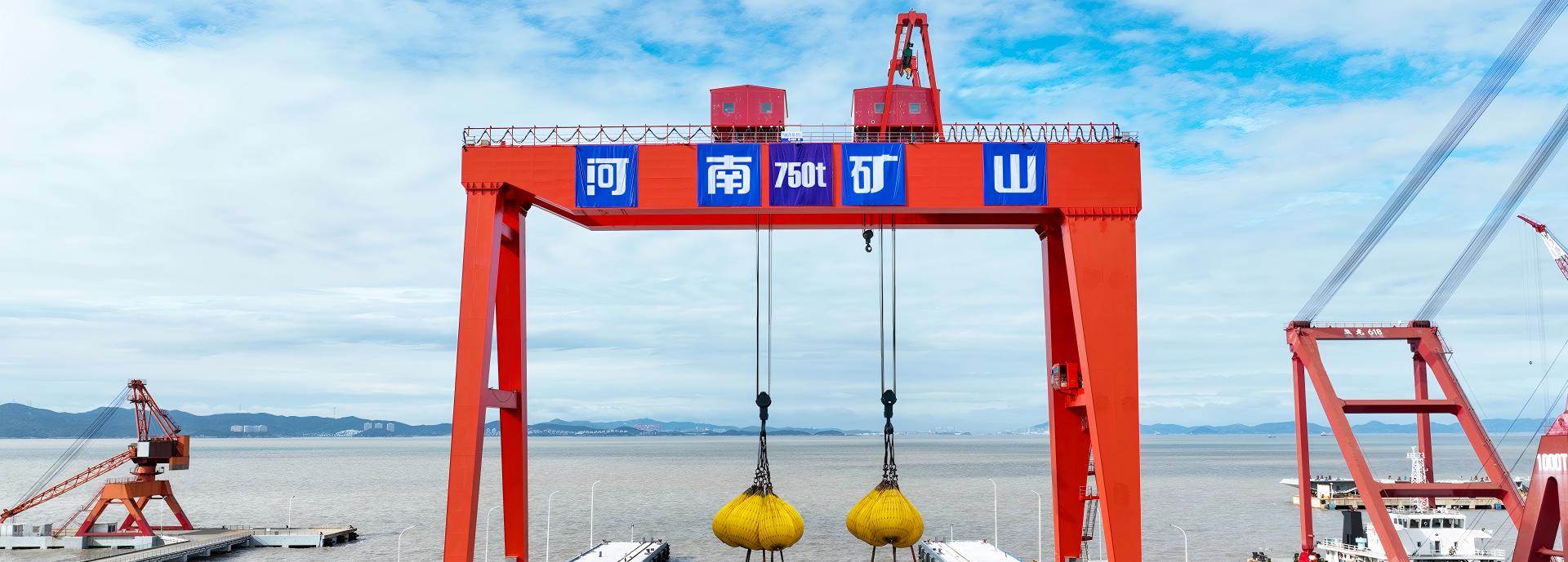
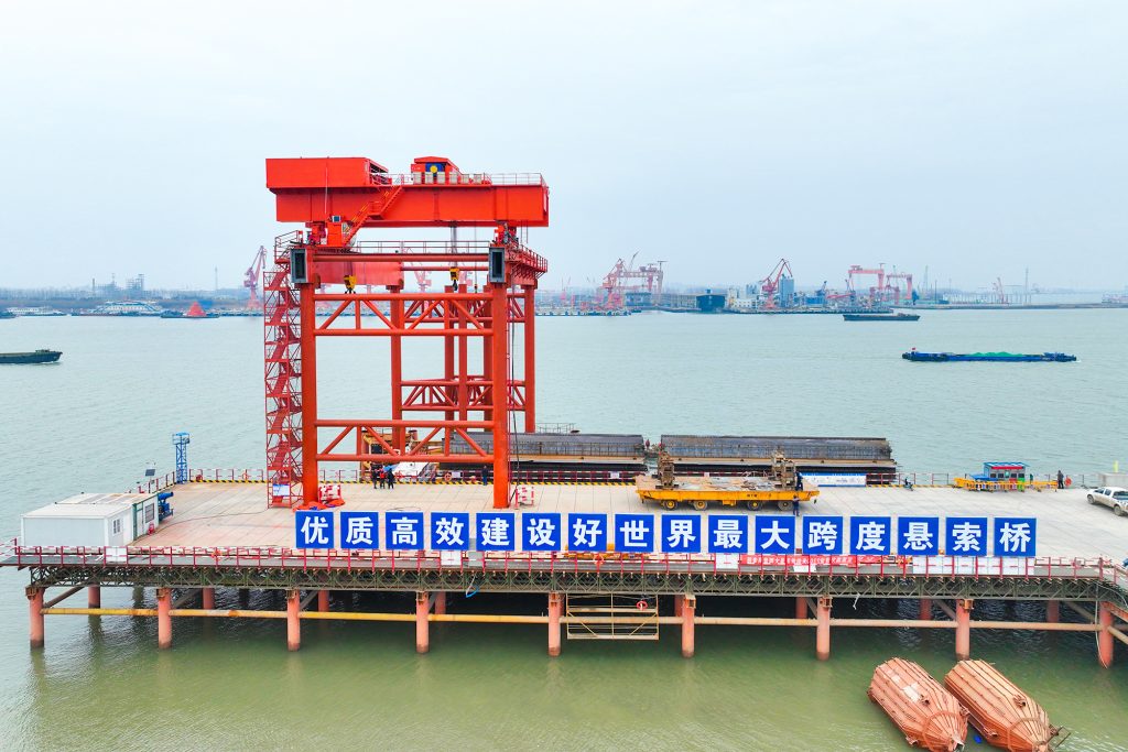
Bridge fabrication, metro construction and ship block assembly.
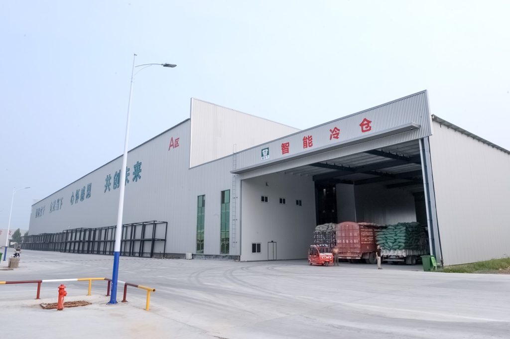
Automated storage and retrieval for plates, cables and bins.
Follow project dispatches, crane engineering and factory acceptance.
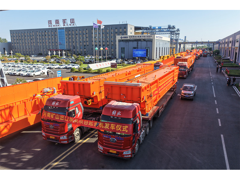
Dispatch, installation and equipment in service
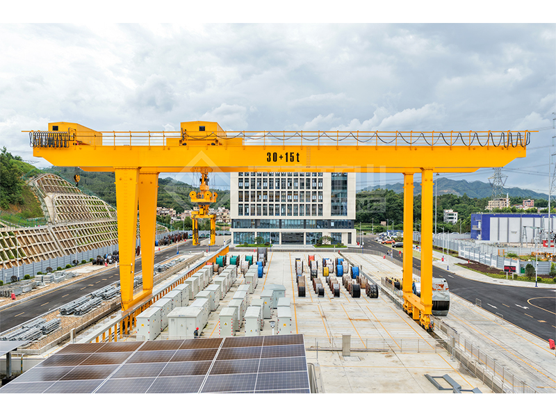
Crane configurations and handling technology
Factory inspections, acceptance and test programmes

Company developments, people and community programmes
Explore the linear full-contact pressure distribution beneath a rigid rectangular base under compression and two moments.
Keep length along x and width along y consistent with the diagram and the applied moments.
Use compression for N and the signed moments about the x and y axes.
If a trial corner pressure is negative, the no-tension full-contact assumption no longer represents the actual contact area.
4 m length, 3 m width, 1,200 kN compression, 150 kN·m about x and 200 kN·m about y.
Mean pressure is 100 kPa. The four trial corner values are 150, 100, 100 and 50 kPa, so all remain non-negative for this entered case.
Non-negative corners establish the assumed full-contact pressure condition only.
Negative trial pressure indicates tension in the linear solution; a no-tension bearing surface needs partial-contact analysis instead.
Pressure values must still be assessed against the relevant soil, footing, anchor and settlement requirements.
Taking moments at the column top and applying them at the footing base without transferring the forces and lever arms.
q(x,y) = N/(L B) + M_x y/I_x + M_y x/I_y
I_x = L B³/12; I_y = B L³/12
q_corners = N/(L B) ± 6M_x/(L B²) ± 6M_y/(B L²)
No. For a no-tension soil interface it is a trial-model warning, not an actual tensile soil pressure.
It does not check soil bearing resistance, settlement, concrete strength, reinforcement, sliding or anchors.