
Rate the actual lifted condition.
Include fuel, water, installed equipment and other weight present during haul-out. Check sling reactions and hull support.
A marine travel lift takes a complete vessel out of the water, carries it through the boatyard and sets it down for service or storage. Select the hoist around your heaviest vessel, approved sling positions, lift basin and actual travel route.
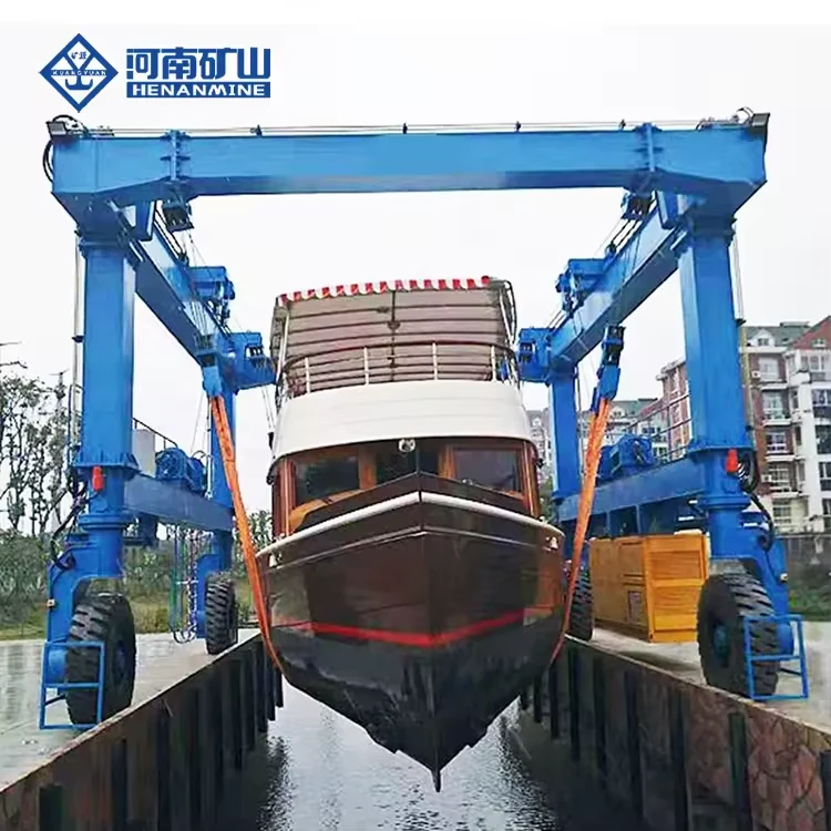
A mobile boat hoist is a rubber-tyred gantry with adjustable lifting slings for handling complete vessels. It works across a launch basin, then travels to a washdown, repair or storage position. The lifting structure, sling geometry, steering arrangement and civil works must be selected together.
Begin with the maximum vessel weight in its lifting condition, not the vessel's length or nominal class. Record hull beam, draft, superstructure, centre of gravity, underwater appendages and approved support zones. Then confirm basin clearances, paving, turns, gradients and the final set-down area.
Include fuel, water, installed equipment and other weight present during haul-out. Check sling reactions and hull support.
Check usable opening, pier geometry, tidal range, water depth and clearances around the hull and appendages.
Route width, turning space, surface bearing and slope determine whether the machine can move the vessel safely.
One yard may serve several hulls. Use the heaviest and most demanding vessel to establish the design envelope, then verify every other vessel's sling locations and clearance.
Frequent haul-outs, narrow access and variable hull shapes make sling adjustment and yard movement central.
Review the marina duty ↓ 02 / BOATYARDPlan for workboat equipment, maintenance access, washdown and an efficient route to repair berths.
Review the yard duty ↓ 03 / SHIPYARDVessel reactions, multiple lifting points, wheel loads and civil interfaces govern the whole project.
Review the large-vessel duty ↓ 04 / MIXED FLEETCompare the full fleet schedule before freezing capacity, sling spacing and the under-beam opening.
See the RFQ schedule ↓These are application paths within the mobile boat hoist family. The final rated load, dimensions, wheel arrangement and lifting points are established from the vessel schedule and site drawings.
Every configuration needs a matched vessel weight, sling-support plan, basin geometry and yard route.
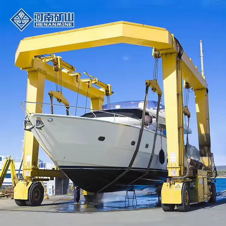 MARINA & YACHT SERVICE
For a marina or yacht service yard, select around the heaviest vessel you will actually lift and the tightest passage the machine must use. Adjustable sling positions matter when hulls differ; confirm support zones against each vessel's lifting plan.
| Vessel schedule | Loaded weight, length, beam and draft for each hull | Sling plan | Approved support zones, appendages and adjustment |
|---|---|---|---|
| Access | Basin opening, route width and turning areas | Handling duty | Haul-outs per day, travel distance and set-down points |
| Site surface | Wheel-load review and paved-route condition | Controls | Operator view and selected steering/control arrangement |
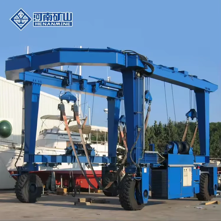 WORKBOAT & REPAIR YARD
A working yard may need to lift different hull forms and move them between launch, washdown and repair positions. Include installed equipment and operating fluids in the lift weight. Check rudders, propellers and keel clearance before deciding sling spacing and travel height.
| Load condition | Maximum actual vessel weight and centre of gravity | Hull interfaces | Sling positions and underwater appendage clearance |
|---|---|---|---|
| Route | Washdown bay, repair berth, gradients and turns | Operating cycle | Daily lift count, travel distance and maintenance access |
| Environment | Salt exposure, washdown and storage conditions | Acceptance | Agreed tests and document package for the unit |
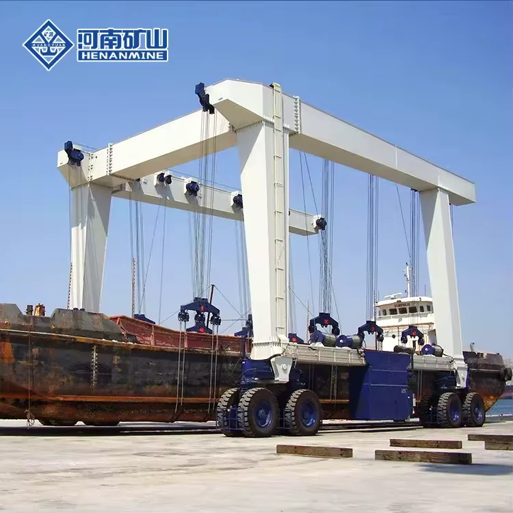 LARGE VESSEL & SHIPYARD
As vessel size grows, the lift becomes a civil and operational project as well as a machine order. Provide the vessel weight distribution and structural lifting points. The final design must match basin geometry, sling reactions, wheel loads, pavement and the full travel path.
| Design vessel | Approved maximum lift mass and centre of gravity | Load sharing | Lifting-point reactions and control strategy |
|---|---|---|---|
| Clearance | Inside width, lift height, draft and superstructure | Civil works | Pier, pavement, wheel loads and turning geometry |
| Site conditions | Wind, tide, corrosion and route gradients | Delivery scope | Assembly, testing, commissioning and training |
Provide the vessel and yard values below. The resulting proposal should return a rated machine configuration, drawings and interfaces for your approval.
| Decision | Send with your RFQ | Confirm in the technical offer |
|---|---|---|
| Rated lift | Maximum actual vessel displacement at haul-out; fluids, equipment and additions included | Rated lifting capacity and operating load schedule |
| Vessel envelope | Length overall, beam, draft, height, centre of gravity and appendage drawings | Clear inside width, lift travel, sling travel and vessel clearance |
| Hull support | Approved sling zones, spacing limits and lift-point reactions | Sling layout, adjustment, protection and load-sharing arrangement |
| Launch basin | Pier plan, opening, water depth and operating water levels | Machine footprint and safe pick-up/launch geometry |
| Yard travel | Route width, slope, turns, paving, bearing capacity and set-down points | Wheel-load schedule, tyre/steering arrangement and route clearances |
| Operation | Lifts per day, travel distance, available power, wind and marine exposure | Controls, drive/power package, operating limits and protection |
| Order scope | Destination, required inspection route, site services and training needs | Drawings, test plan, manuals, packing, installation and warranty terms |
A vessel's length alone does not determine lifting capacity. Approve the loaded vessel mass and hull-support plan before selecting a rated machine or finalising civil works.
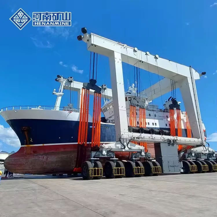
Lift a complete vessel across the basin, keeping the approved slings clear of propellers, shafts, rudders and hull fittings.
Move to washdown, inspection, repair or storage along a surveyed route with known ground bearing and turning space.
Coordinate the hoist and the vessel's approved blocking plan so workers can access the hull and running gear after unloading.
Moving ship sections or containers instead? Compare the gantry crane range and port equipment for those different handling tasks.
Send a vessel list and yard plan early. These details govern the rated load, machine opening, sling system and civil interface.
Discuss your project ↗No. Use the maximum actual weight in the condition in which the vessel will be lifted. Include fluids and onboard equipment, then review weight distribution and sling reactions.
Yes, if each vessel fits the rated load, clear opening, lifting height and approved sling-support range. Submit a vessel schedule rather than only the largest hull.
Mark every underwater appendage and no-lift zone on the vessel drawing. Sling positions and lift height must clear these features through the entire haul-out and travel cycle.
Provide route dimensions, gradients, turning areas, pavement structure and allowable bearing values. The selected machine's wheel loads must be checked against the route and set-down locations.
No. A marine travel lift uses slings to haul and transport a complete vessel. A container RTG handles containers; a shipbuilding gantry handles fabrication loads. Start from the actual load and movement task.
State the destination, required approvals and number of units in your RFQ. The selected machine's documentation, production schedule, inspection, warranty and service scope should be stated in the written offer.
Share each vessel's maximum loaded weight, length, beam, draft, centre of gravity and approved sling zones. Add the basin drawing, route plan, ground bearing, working cycle and destination. Request the rated machine, load schedule, drawings, documentation and delivery scope in one proposal.
Request a technical quotation