Skip to content
CRANE MANUFACTURER SINCE 2002
info@hnksglobal.com+86 188 3620 7779Project enquiry ↗
Henan Mine Crane Request a quote
Complete U-Type Product Family

U-Type Gantry Cranes

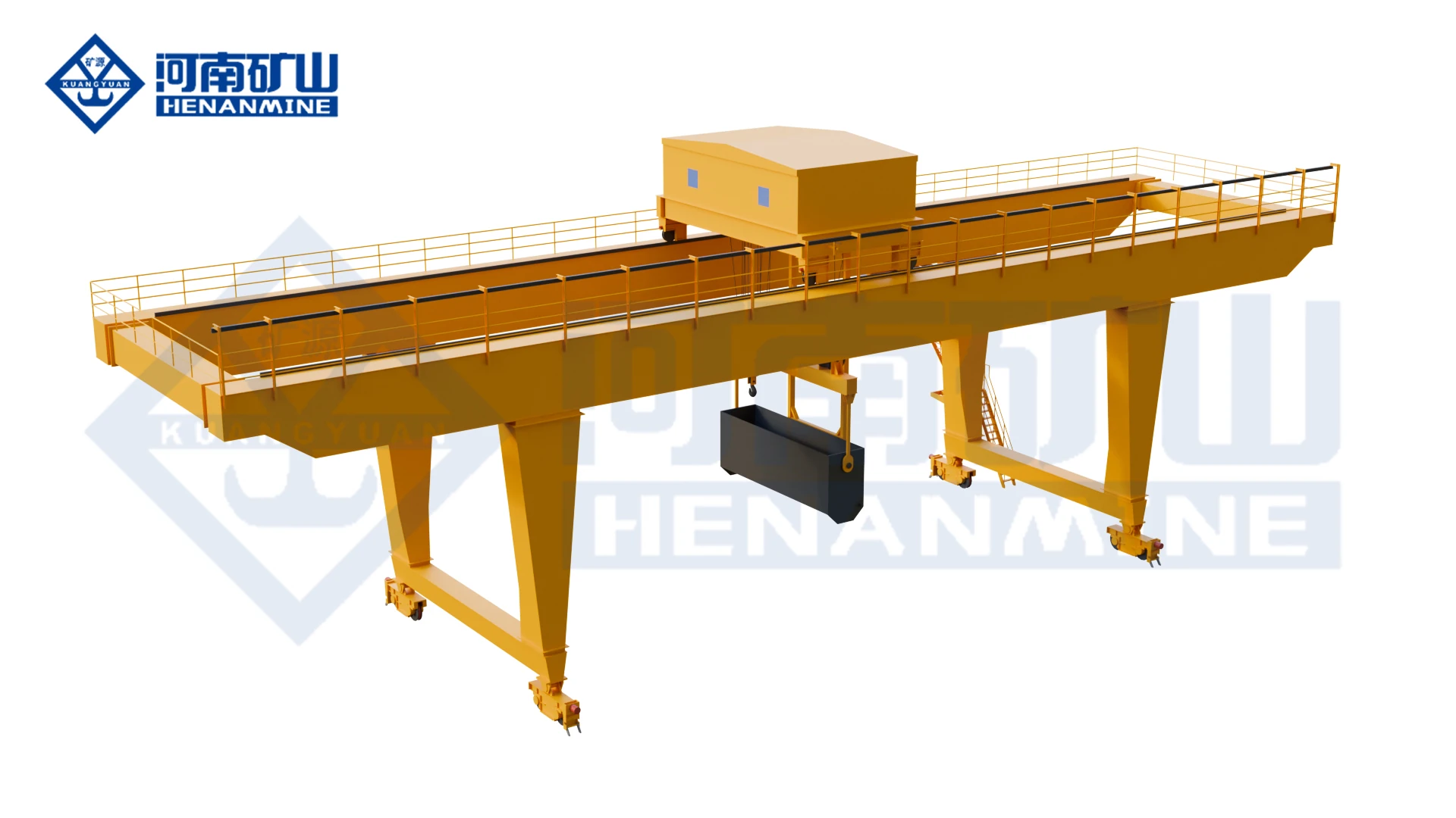
U-frame gantry crane systems for long and bulky cargo, railway freight yards, ports, open warehouses, container-transfer stations and subway construction. The U-shaped legs provide large clear passage through the portal, reducing interference when long loads move or rotate beneath the crane.

View Complete RangeRequest U-Type Proposal
U-type double-beam hook gantry crane official selection guide
10–50/10 t U-type hook family
18–35 m U-type hook span range
A5 general U-type hook duty
~7 m ClearanceNearly 7 m leg clearance in listed configurations
Product Family Structure

Complete U-Type Gantry Crane Collection

The U-type structure is selected where cargo passage through the legs is more important than the compact inclined-leg geometry of an A-type portal. General hook handling and subway/slag applications use different lifting systems, duty and below-rail lifting requirements.

Core U-Type Gantry Cranes

Core U-Type Gantry Cranes

The classic U-frame double-girder family for long, bulky and high-clearance cargo handling.

U-Type 10–50/10 t Double-Beam Hook Gantry Crane
U-GANTRY

U-Type 10–50/10 t Double-Beam Hook Gantry Crane

A classic U-frame double-girder hook gantry crane for railway freight yards, ports, open warehouses and container-transfer stations. The near-vertical U-shaped legs create a large clear passage for long and bulky cargo that can be restricted by inclined A-frame legs.

10–50/10 t Family18–35 mA5Large Leg Clearance
Technical Specifications
Technical FamilyU Type 10–50/10 t Double-Beam Hook Gantry Crane
Capacity Entries10 t, 16 t, 20/10 t, 32/10 t, 36/16 t, 50/10 t
Span Range18–35 m, depending on capacity
Working ClassA5
Main Hoisting Speed6–8.5 m/min across configurations
Auxiliary Hoisting SpeedApprox. 10.4–10.5 m/min where auxiliary hoist is provided
Trolley Travel SpeedApprox. 38.13–44.5 m/min
Crane Travel SpeedApprox. 36–40 m/min
Wheel-Pressure EnvelopeApprox. 208–452 kN across the crane series
Recommended RailP43 on lighter configurations; 50 kg/m / QU70 on heavier configurations
Power Supply3-phase AC 380 V / 50 Hz in the Technical Specifications
Structural CharacterU-shaped portal with large clearance between the legs
ApplicationRailway freight yard, port, open warehouse and container-transfer station
Special U-Type Process Gantry Cranes

Special U-Type Process Gantry Cranes

U-frame process crane configurations for subway and heavy civil construction.

U-Type Subway Turn-Slag Hook Gantry Crane
U-SUBWAY

U-Type Subway Turn-Slag Hook Gantry Crane

This U-type subway crane combines 75 t rated lifting, M6 duty and deep below-rail hook travel for heavy civil construction.

75 tM6Subway / SlagDeep Lifting
Technical Specifications
Technical FamilyU Type Subway Turn-Slag Hook Gantry Crane
Rated Capacity75 t
Working ClassM6 in the technical table
Hoisting Speed1 / 10 m/min
Maximum Lifting HeightApprox. +10 m above rail / 16.5 m below rail
Trolley Gauge9,000 mm
Crane Gauge / Span30,000 mm
Trolley Travel Speed2 / 20 m/min
Crane Travel Speed3 / 30 m/min
Trolley RailP43
Crane Rail50 kg/m
Maximum Wheel Pressure285 kN trolley-side configuration / 248 kN crane-side configuration in the technical table
Main Hoist MotorYZP400L1-10, 160 kW, 585 r/min configuration
Power Supply3-phase AC 380 V / 50 Hz
Current Subway Slag Product Family

Current Subway Slag Product Family

MGC subway slag cranes provide variable span and bucket turnover for demanding tunnel projects.

MGC Subway Slag Double-Girder Gantry Crane
MGC

MGC Subway Slag Double-Girder Gantry Crane

MGC supports tunnel spoil lifting, bucket transfer and automatic overturning. Confirm portal geometry, lifting height and site clearances for the construction plan.

Current Product45–50 t TypicalUp to 100 m LiftVariable Span
Technical Specifications
Type-Test ModelMGC
Type-Test ProductGeneral Gantry Crane
Typical Capacity45–50 t in the Available configurations description
Maximum Lifting HeightUp to 100 m
DutyHeavy-duty construction service
Primary ProcessTunnel spoil lifting, transfer, overturning and segment handling
Trolley Function180° trolley rotation available to adjust discharge direction
Crane Travel8-wheel / 4-drive arrangement
Outdoor SafetyWind rail clamp + anchoring device
Variable SpanCan be configured for changing construction locations
SafetyOverload protection, travel limits, buffers and wind protection
Technical Matrix

U-Type Double-Beam Hook Gantry Crane Technical Series

Compare the A5 U-type capacity and span configurations below, then specify wheel loads, motors and dimensions for your site.

Capacity SpanClassMain Lift m/minAux Lift m/minTrolley m/minCrane Travel m/minRail
10 t18 / 22 / 26 / 30 / 35 mA58.5—43.837.6–40P43
16 t18 / 22 / 30 mA57.9—44.536–38P43 / project-dependent heavier rail
20/10 t18 / 22 / 26 / 30 / 35 mA57.210.444.536–3850 kg/m / QU70 family
32/10 t22 / 26 mA57.510.441.94050 kg/m / QU70 family
36/16 t22 / 26 / 30 / 35 mA57.810.541.938–4050 kg/m / QU70 family
50/10 t35 mA5610.438.133850 kg/m / QU70
Structural Selection

U-Type vs A-Type Gantry Crane

Selection FactorU-Type Gantry CraneA-Type Gantry Crane
Leg GeometryNear-vertical / U-frame legsInclined A-frame legs
Portal ClearanceLarge clear passage; official guide describes nearly 7 m clearance between legs on the U-familyInclined legs occupy more lateral space near the portal
Long / Bulky CargoStrong choice where cargo must pass between legs or rotate with minimal interferenceSuitable for general heavy lifting when the cargo envelope fits the inclined-leg geometry
Typical SitesRailway freight yards, ports, open warehouses, transfer stationsGeneral outdoor yards, heavy machinery and industrial lifting
Engineering FocusLeg clearance, long-load envelope, wheel load, rail and outdoor stabilityLeg bracing, cantilever, wheel load, foundation and wind stability
Engineering Requirements

Critical U-Type Gantry Crane Design Factors

Clear Passage Between Legs

Define maximum load width, vehicle path and turning envelope. U-type selection begins with the clear opening needed through the support legs.

Wheel Load & Rail

U-type tables extend from P43 to 50 kg/m / QU70 rail families. Final rail and foundation must use actual wheel loads and load combinations.

Long-Load Rotation

Where beams, pipes or bulky cargo rotate under the crane, check the full swept envelope against legs, stairs, electrical equipment and ground obstacles.

Outdoor Wind Protection

Rail clamps, anchors and parked-storm conditions should be selected from project wind speed and exposed area.

Deep Below-Rail Lifting

Subway/shaft projects require separate checks for rope capacity, drum capacity, hook travel below rail and emergency retrieval.

Transfer-Station Interface

Coordinate rail position, truck/railcar clearance, container or long-load traffic lanes and material-flow route before fixing span and leg spacing.

Application Selection

Typical U-Type Gantry Crane Applications

Railway Freight Yard

The open U-frame provides clearance for long cargo, loading equipment and rail-side material transfer.

Port & Open Warehouse

Suitable for frequent outdoor handling where bulky loads must move through the portal without leg interference.

Container Transfer Station

The U-frame's clear passage suits long loads and container-transfer stations. For dedicated container yards, compare the required handling cycle with an RMG crane.

Long Steel / Fabricated Loads

Large leg clearance supports beams, pipes and fabricated modules requiring wide passage.

Subway Slag Handling

The U-SUBWAY family combines heavy lifting with below-rail hook travel for subway and civil construction.

Modern Tunnel Construction

Current MGC systems add variable span, 180° trolley rotation and automatic spoil-bucket overturning for changing construction sites.

Engineering RFQ

Request a U-Type Gantry Crane Proposal

Provide capacity, span, lifting height, required clear opening between legs, cargo dimensions, turning envelope, runway length, rail/foundation condition and wind data. Subway projects should also include shaft depth, below-rail lifting height, spoil bucket dimensions and overturning process.