
Fabricated loads
Lift wide or irregular assemblies between defined positions. Include lifting gear, load depth and the nearest supports when checking the leg opening and usable hook approaches.
Bridge cranes for workshops and production lines.
Explore Overhead Cranes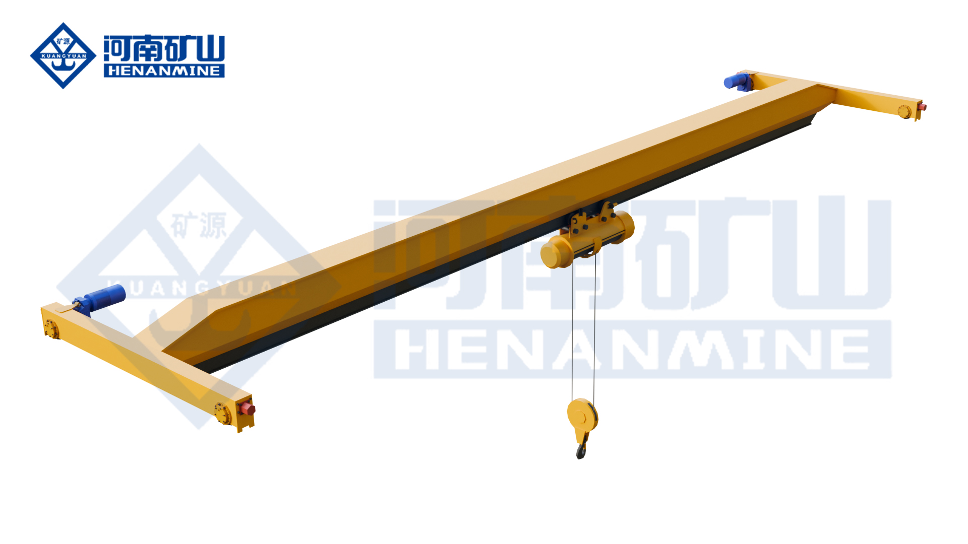
Ground-supported lifting for yards and construction.
Explore Gantry Cranes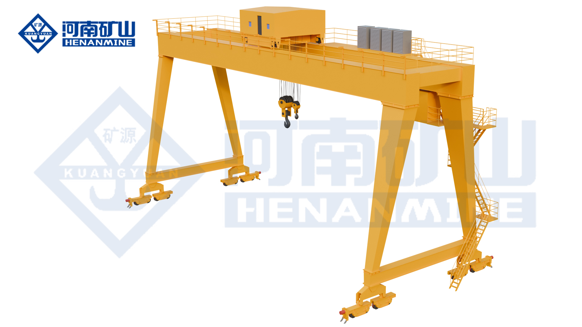
Wire rope and chain hoists for lifting points and cranes.
Explore Electric Hoists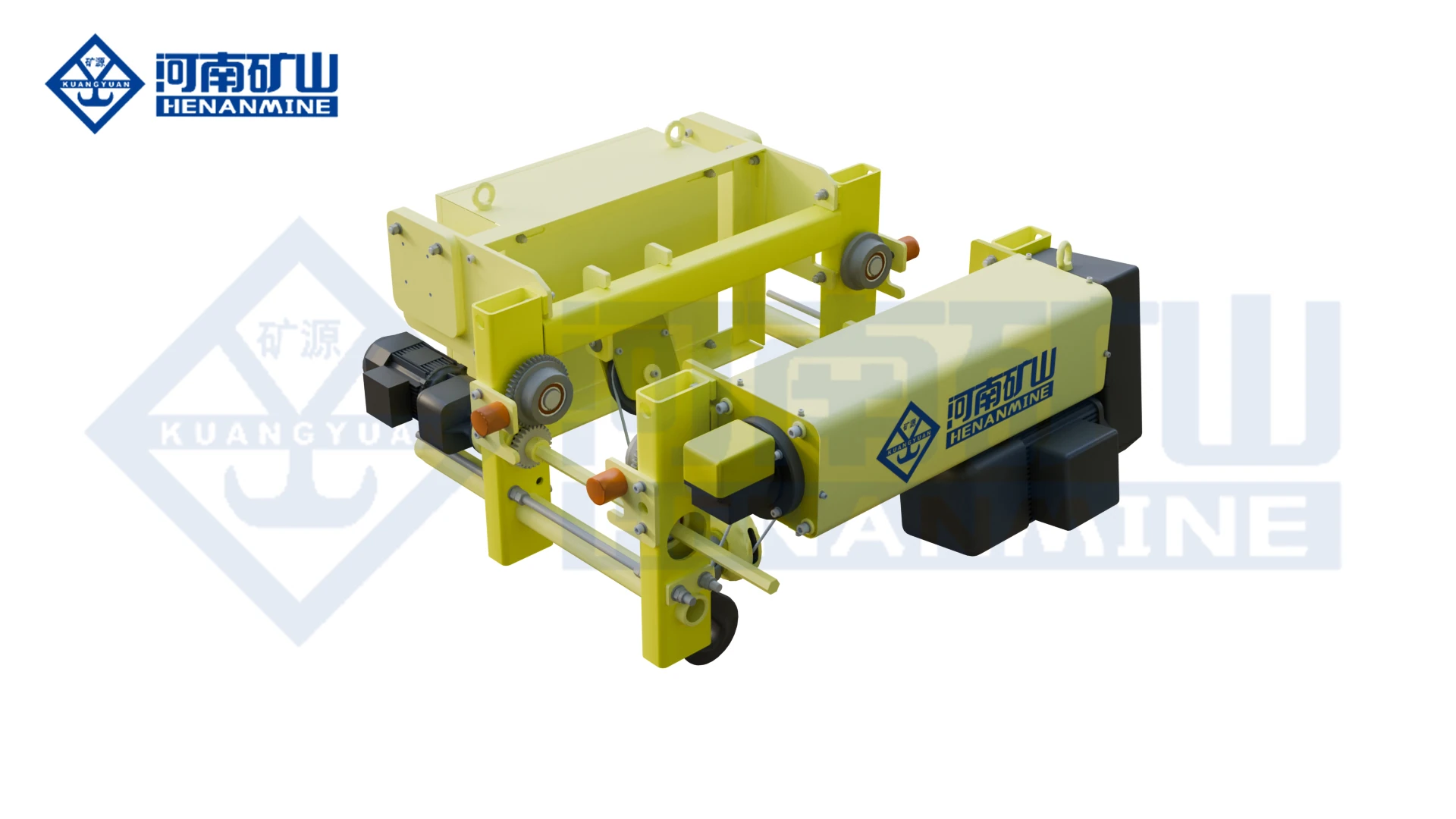
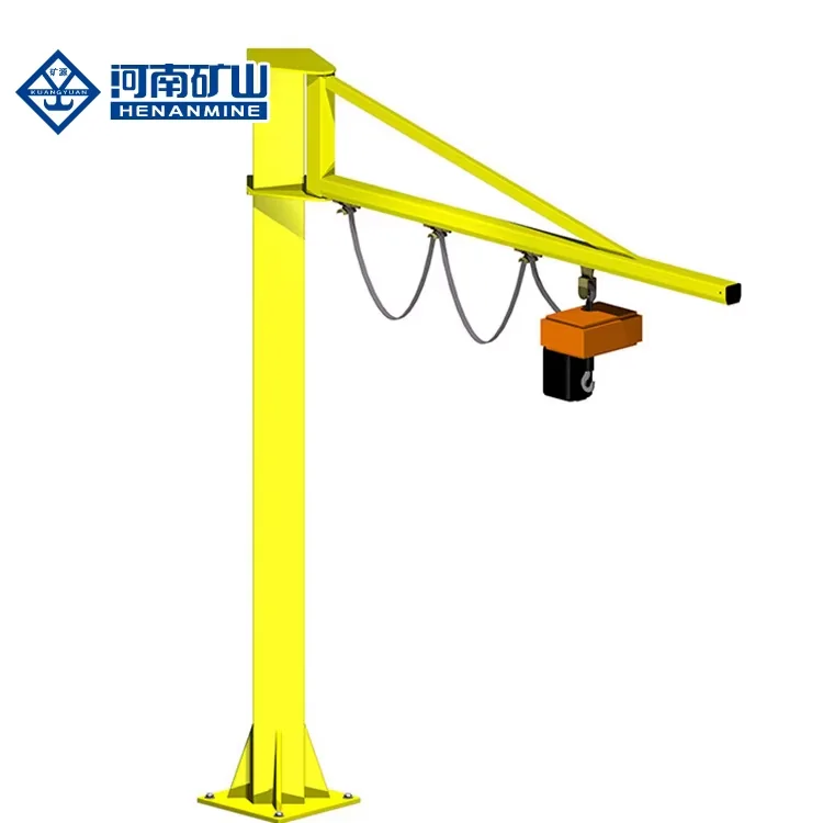
Wire rope lifting and pulling with a powered drum.
Explore Electric Winches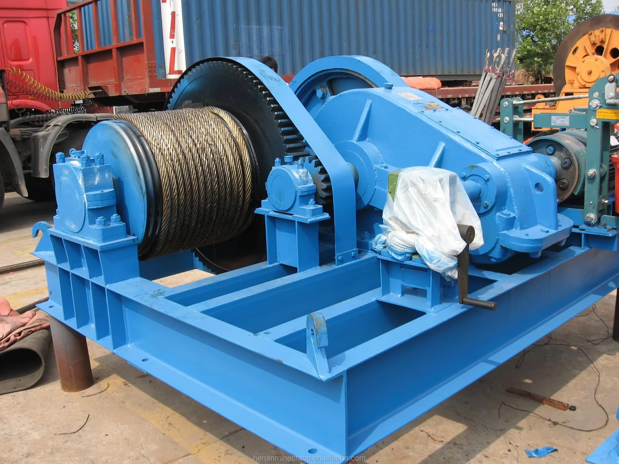
Grab buckets, magnets and hooks for your load.
Explore Lifting Attachments & Grabs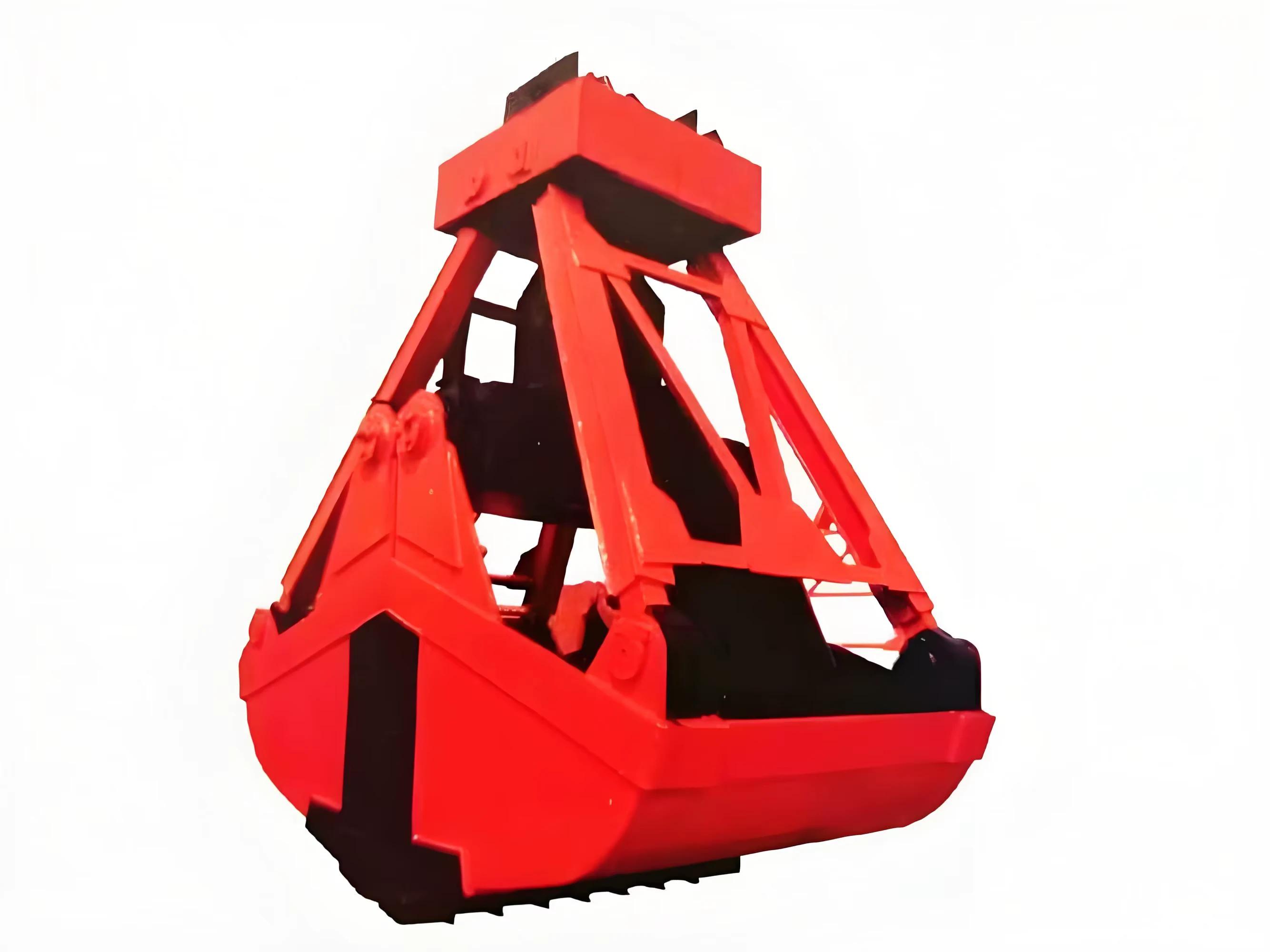
Mobile handling for containers, precast and yard loads.
Explore Rubber-Tired Gantry Cranes & Straddle Carriers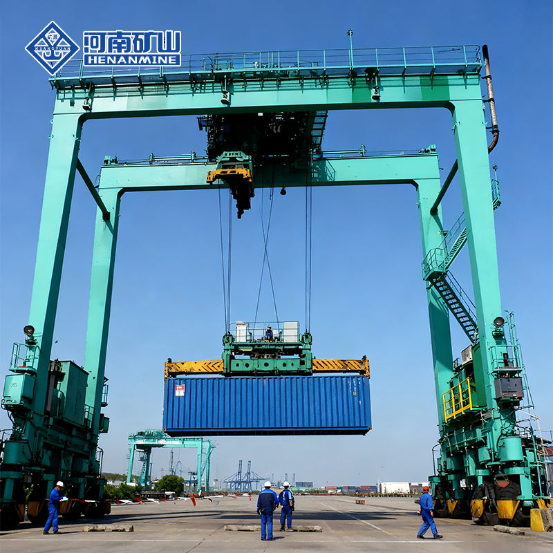
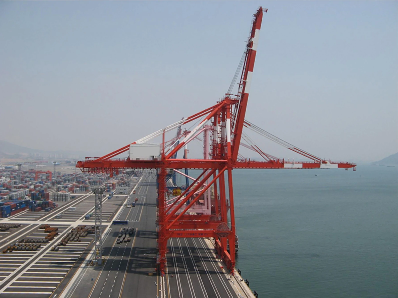
Lift and move vessels through boatyards and marinas.
Explore Marine Travel Lifts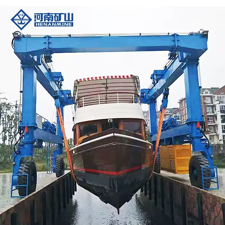
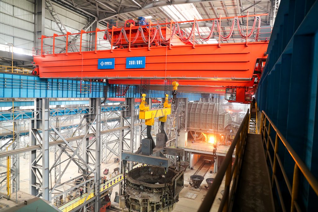
Ladle, slab, scrap and coil handling across steel production.
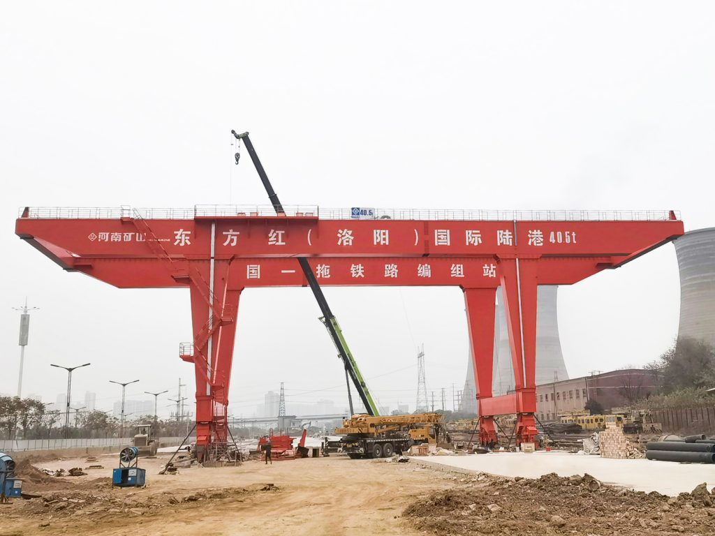
Container stacking and cargo transfers across terminals and rail.
Turbine installation, powerhouse maintenance and wind equipment assembly.
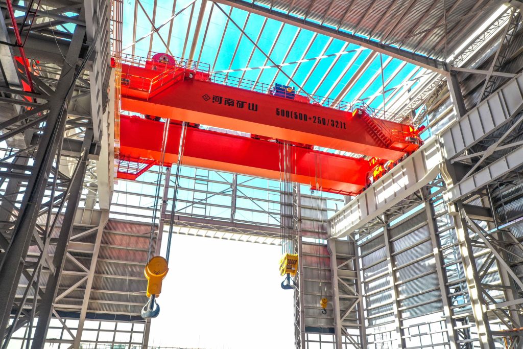
Controlled component transfer and positioning for precision assembly.
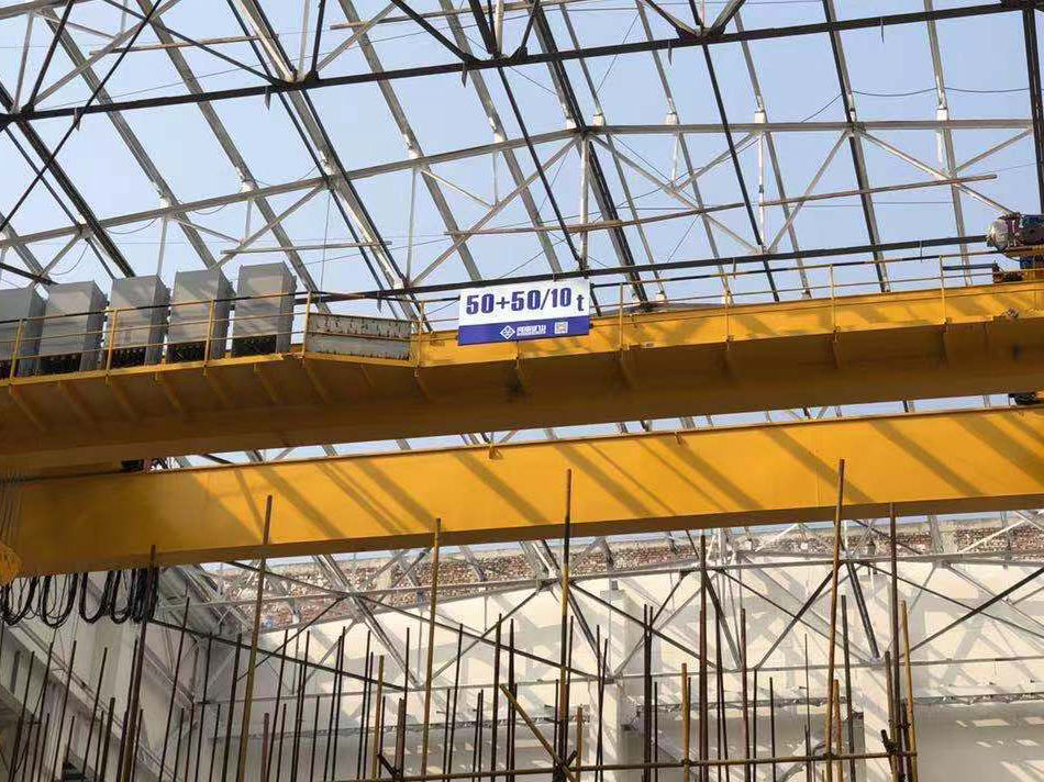
Heavy fabrication, production lifting and factory crane automation.
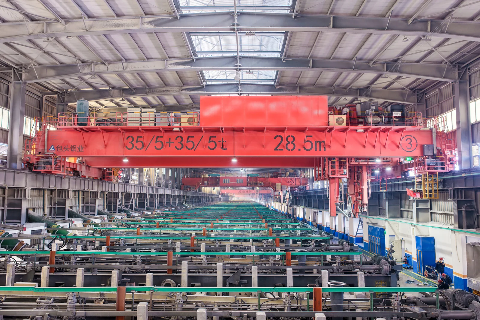
Process lifting for smelters, carbon blocks and anode materials.
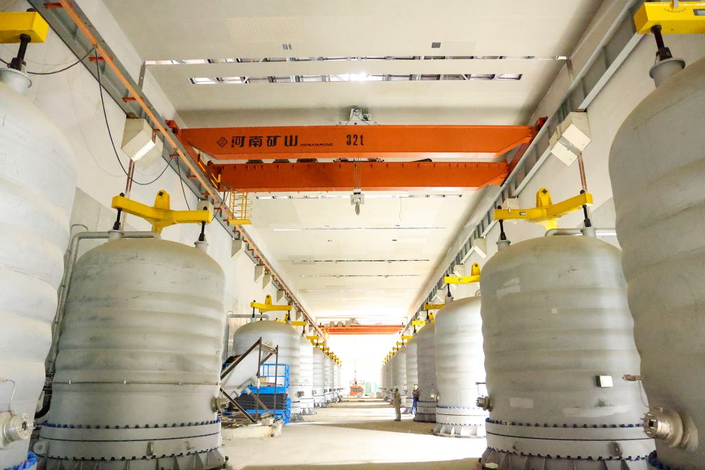
Clean lifting and classified protection for sensitive process areas.
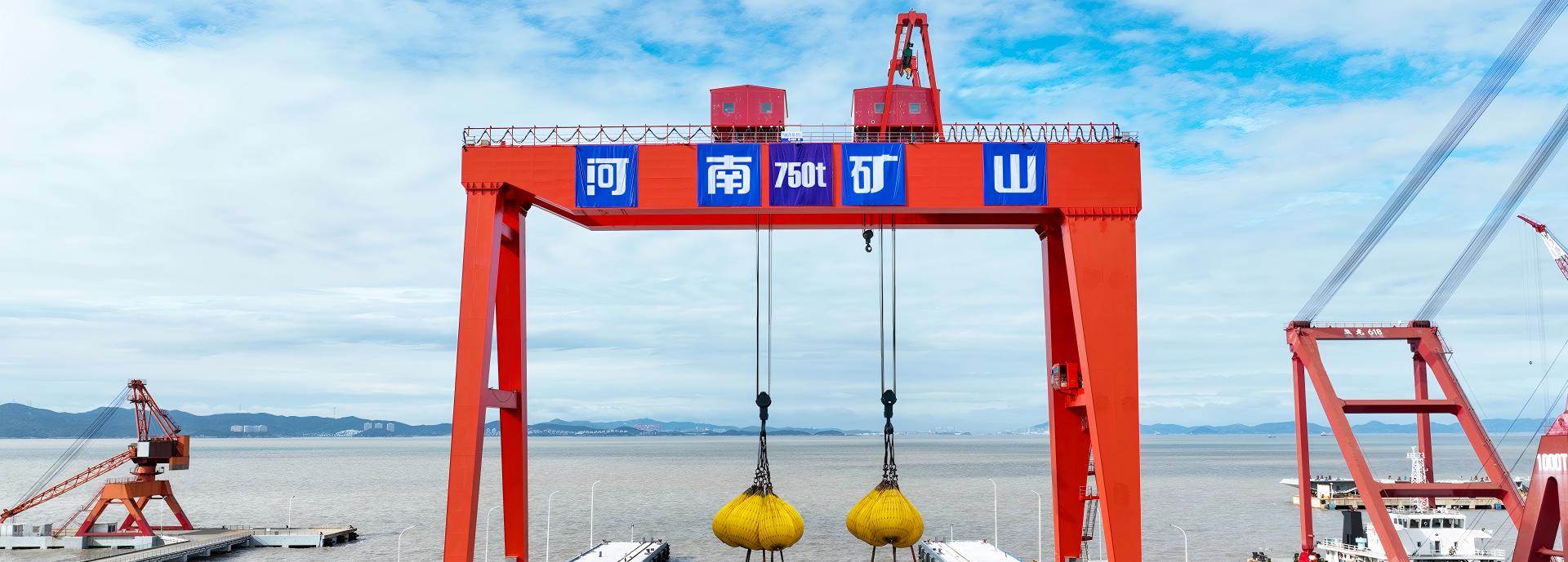
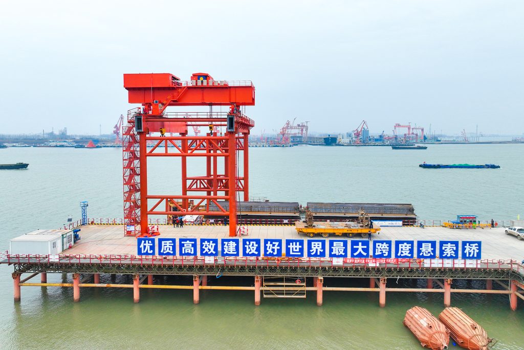
Bridge fabrication, metro construction and ship block assembly.
Automated storage and retrieval for plates, cables and bins.
Follow project dispatches, crane engineering and factory acceptance.
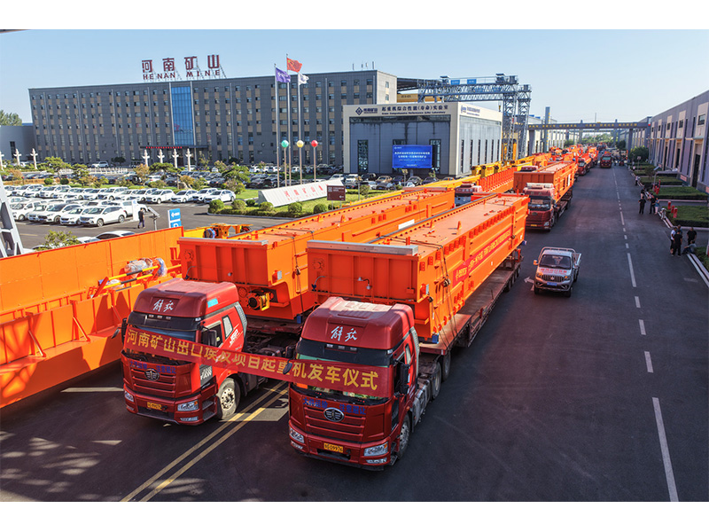
Dispatch, installation and equipment in service
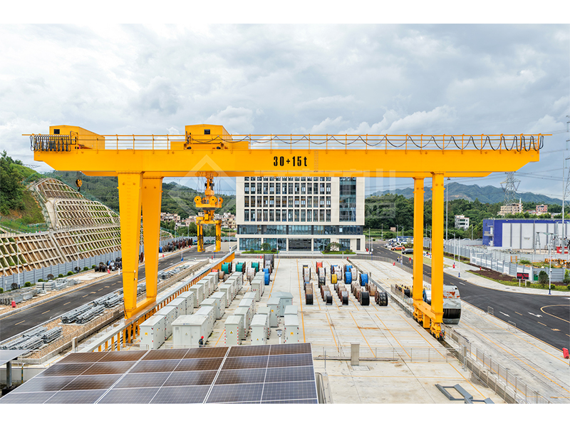
Crane configurations and handling technology
Factory inspections, acceptance and test programmes

Company developments, people and community programmes
Choose a U-type hook gantry for loads whose width, lifting points and movement route need a clear operating envelope. Compare the selected rated load, span, lift and mechanism speeds as one configuration. The U-shaped support geometry and hook approaches should match the actual pickup and set-down positions.
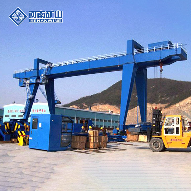
Use the load dimensions and handling route to select the U-type arrangement, attachment and useful hook coverage.
Lift wide or irregular assemblies between defined positions. Include lifting gear, load depth and the nearest supports when checking the leg opening and usable hook approaches.
Move material along the planned runway to storage or vehicle-loading positions. Confirm rail spacing, travel length, truck access and the clear route for the suspended load.
Position heavy components for planned fitting or service work. Match the hook height and mechanism speeds to the task, with floor or foundation support checked for the selected reactions.
Capacity, span, useful hook travel and mechanisms are confirmed together for the quoted unit.
| Parameter | Reference selection range | Procurement check |
|---|---|---|
| Capacity Range | 10 / 16 t single-hook options; 20/10, 32/10 and 50/10 t main/auxiliary options | Confirm the selected lifting rating and complete suspended load, including attachments; agree any main and auxiliary hook load cases. |
| Span Range | 18–35 m | Confirm the runway rail centre-to-centre span and required hook coverage on the approved general arrangement drawing. |
| Working Class | A5 | Select the duty class for the load spectrum, operating hours and handling frequency. |
| 10 t Main Hoisting Speed | 8.5 m/min | Confirm the selected hoisting speed, approach control and positioning requirement for the stated capacity. |
| 16 t Main Hoisting Speed | 7.9 m/min | Confirm the selected hoisting speed, approach control and positioning requirement for the stated capacity. |
| 20/10 t Main / Aux Speed | 7.2 / 10.4 m/min | Confirm main and auxiliary hoisting speeds separately for the selected capacity and positioning task. |
| 32/10 t Main / Aux Speed | 7.5 / 10.4 m/min | Confirm main and auxiliary hoisting speeds separately for the selected capacity and positioning task. |
| 50/10 t Main / Aux Speed | 6 / 10.4 m/min | Confirm main and auxiliary hoisting speeds separately for the selected capacity and positioning task. |
| Trolley Travel Speed | Approx. 38.13–44.5 m/min by configuration | Confirm trolley speed, available travel and stopping position for the handling route. |
| Crane Travel Speed | Approx. 36–40 m/min by configuration | Confirm crane travel speed, runway travel and stopping requirements for the selected configuration. |
| Maximum Wheel Pressure | configurations extend approximately 208–452 kN | Confirm the governing wheel reactions for the selected configuration and verify the runway and foundation design. |
| Recommended Rail | P43 on lighter configurations; 50 kg/m / QU70 on heavier configurations | Confirm the rail section, wheel compatibility, support reactions and installation tolerances for the selected configuration. |
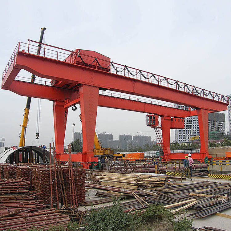
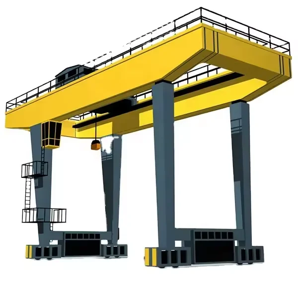
Include payload, rigging and any attachment or carrier beam. Identify lifting points and load centre, then select the rated configuration and mechanisms as one package.
Mark rail centres, runway length, useful lift and hook approaches. Include load width, obstacles and the clearance required through the U-shaped support arrangement.
State loads per cycle, cycles per hour, shifts and positioning needs. Compare the quoted lifting and travel speeds with the actual pickup, travel and placement sequence.
Provide support capacity, power and destination requirements. Request hook coverage, crane reactions, the named equipment, inspection scope and agreed site responsibilities in the offer.
Order one complete crane or define a project package. Itemise the U-type bridge and supports, selected lifting mechanism, travel drives, controls and protection.
Request the selected load, dimensions and mechanisms, arrangement drawing, reactions, operating and electrical information, applicable inspection/test records and destination conformity documents.
Agree the production, factory inspection and dispatch dates after configuration approval. Confirm packing, transport dimensions, freight route and unloading access separately from site work.
Define site readiness, personnel and equipment for assembly, electrical hookup, commissioning and load testing. Agree operator information, training and the factory/site acceptance requirements.
Put warranty duration and component coverage in the offer. Separate wear parts and site-service costs; agree installation guidance, engineer attendance and model-matched maintenance parts.
State the approved equipment, support or floor interfaces and each party’s responsibilities. Include shipping terms, installation boundaries, handover documents and after-sales response in the contract.
Request service and warranty terms ↗Review related equipment against your load, site geometry and operating cycle.

Compare an A-frame hook gantry for the same load and yard duty.
View details ↗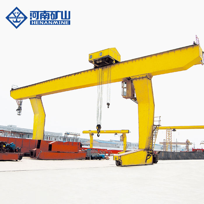
Compare L-leg access where side clearance governs the layout.
View details ↗Review the available lifting arrangements and selection requirements.
View details ↗Check the selection, commercial scope and installation requirements before ordering.
No. Confirm vehicle clearance, load width, hook approach and leg geometry on the approved general arrangement.
Only after the selected combination and wheel loads are approved on a model-specific drawing.
Request a quotation for one crane or a project package; the offer should state the minimum quantity and complete supply scope.
Ask for calendar days from deposit and approved drawings to factory dispatch, with freight and site work shown separately.
Share the complete load, arrangement, rail centres, lift, duty, site conditions, destination and required delivery scope. We can return a model-specific drawing, selected specifications and a dated quotation.
Discuss your project