
Aircraft manufacturing
Move aircraft sections, tooling and production equipment between defined positions. Select hook coverage around the assembly stations and access required for the workpiece.
Bridge cranes for workshops and production lines.
Explore Overhead Cranes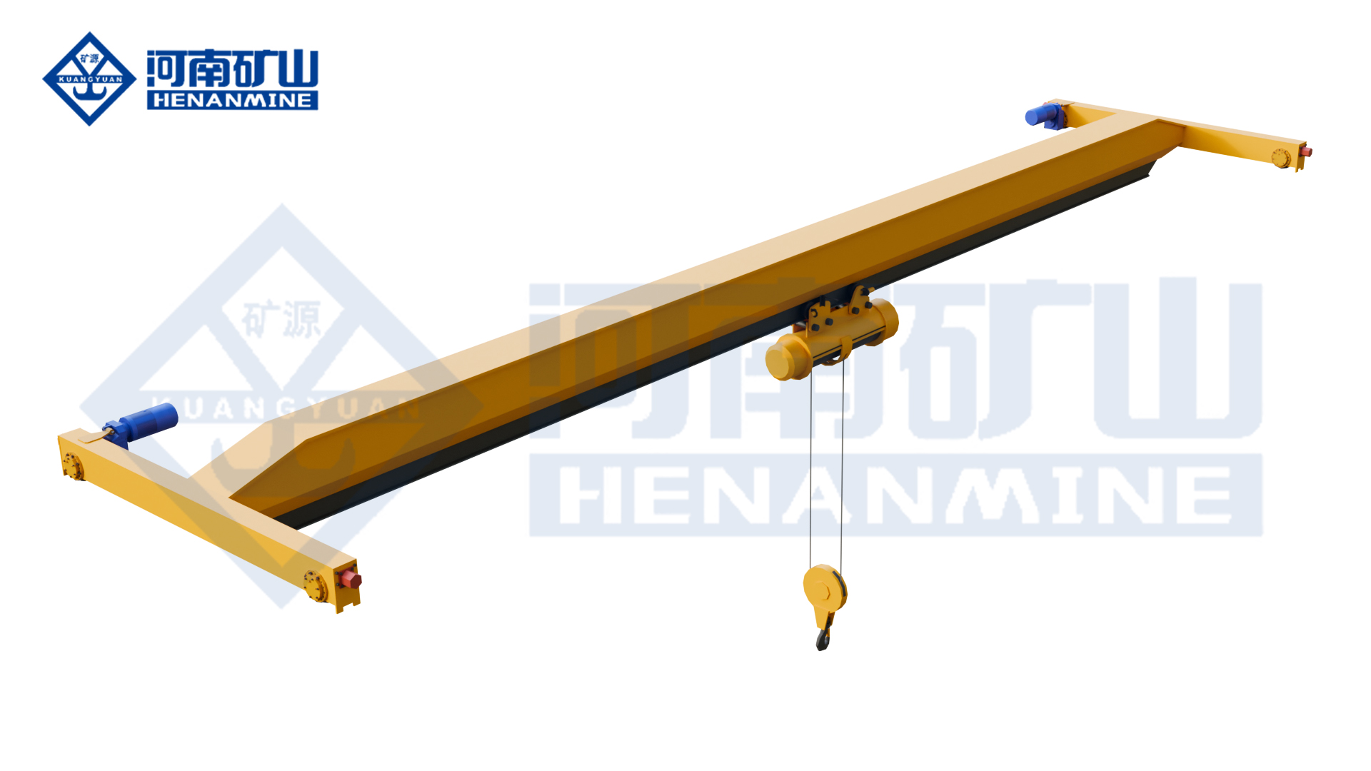
Ground-supported lifting for yards and construction.
Explore Gantry Cranes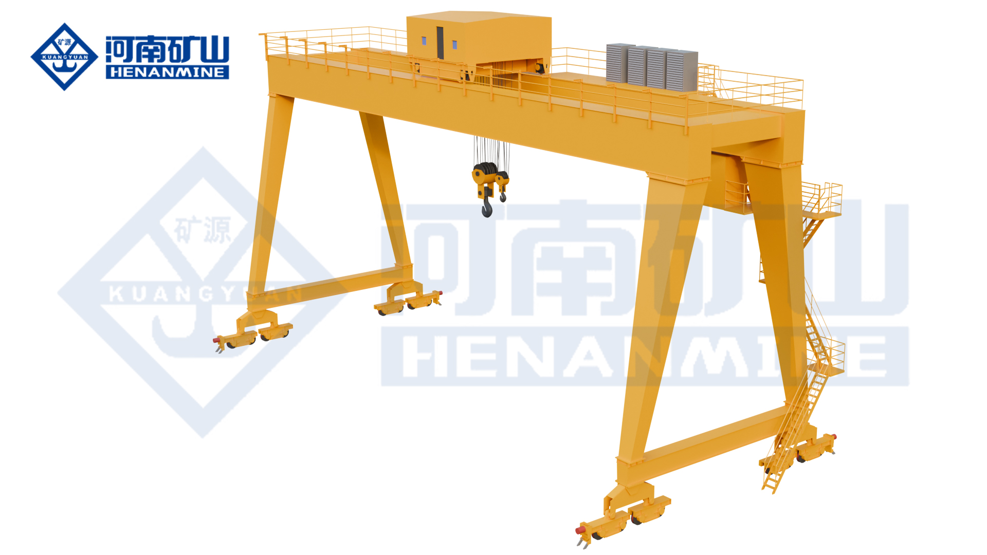
Wire rope and chain hoists for lifting points and cranes.
Explore Electric Hoists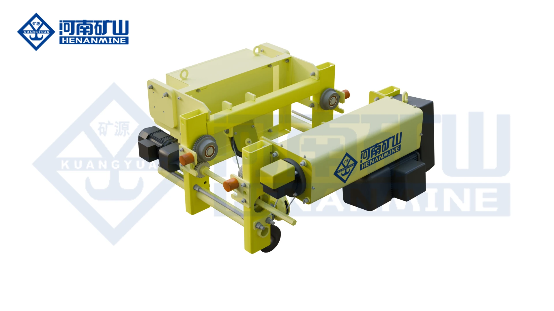
Wire rope lifting and pulling with a powered drum.
Explore Electric Winches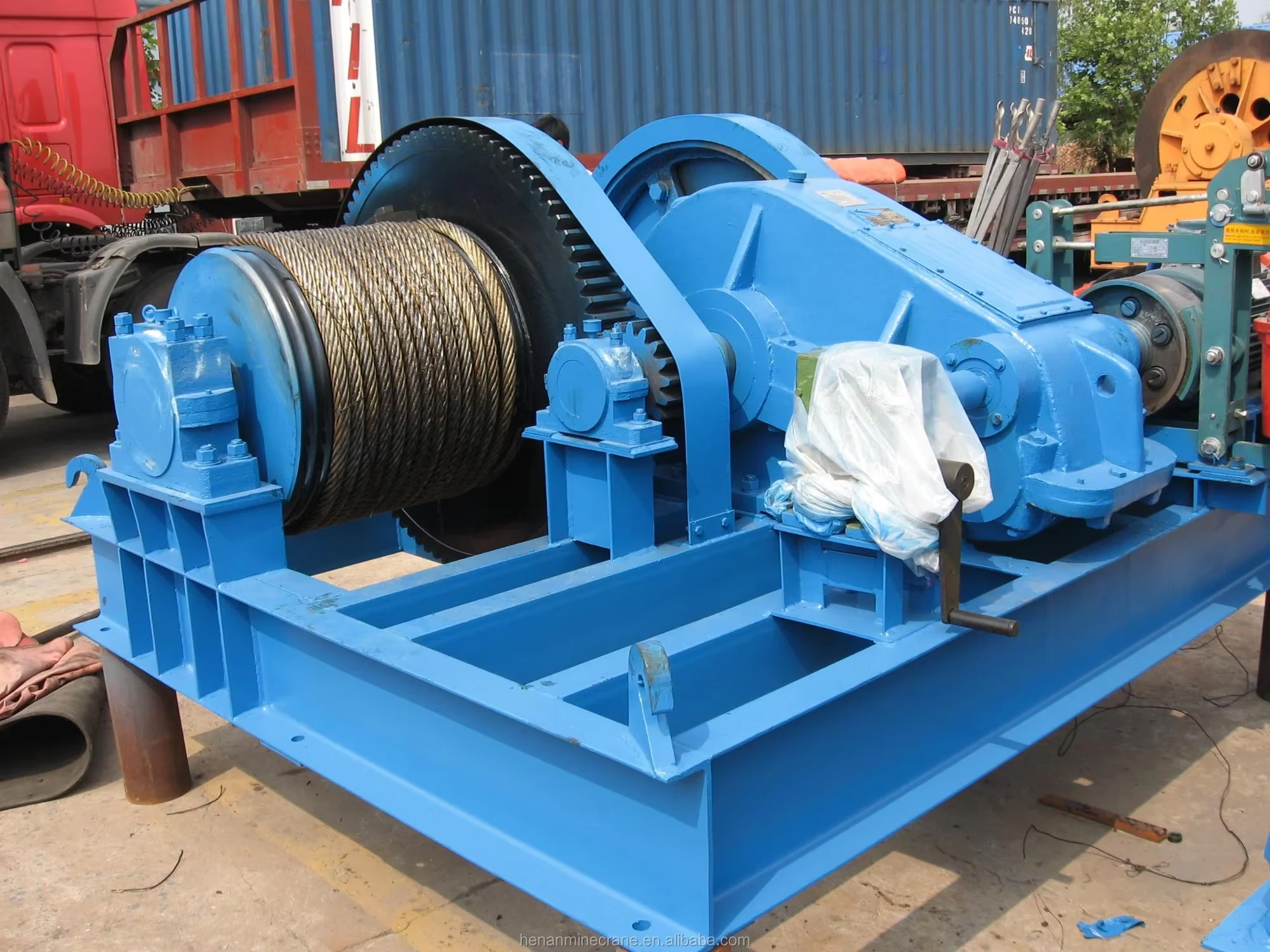
Grab buckets, magnets and hooks for your load.
Explore Lifting Attachments & Grabs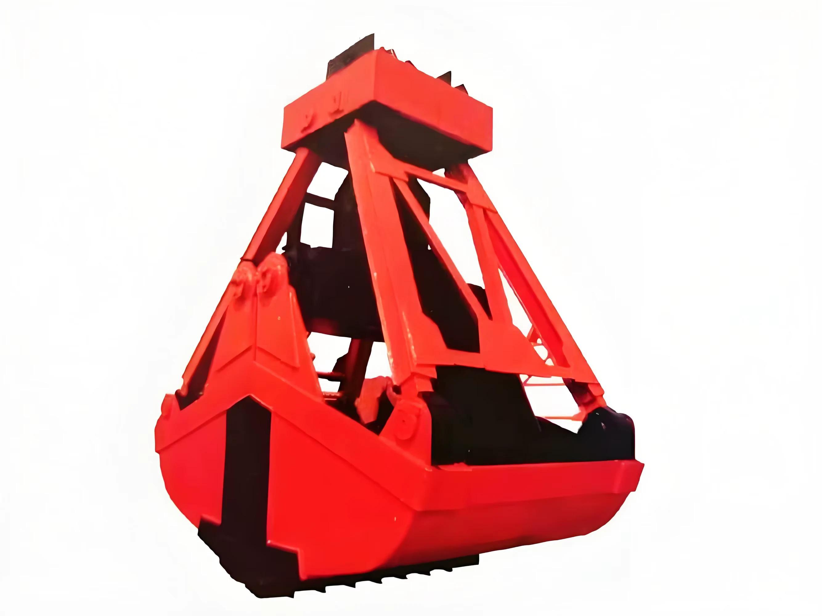
Mobile handling for containers, precast and yard loads.
Explore Rubber-Tired Gantry Cranes & Straddle Carriers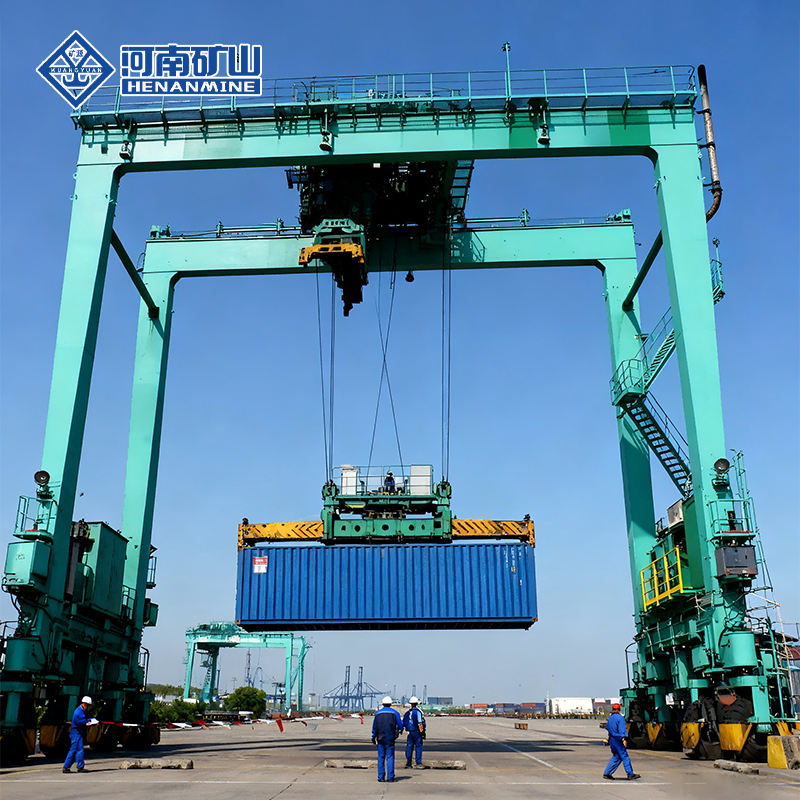
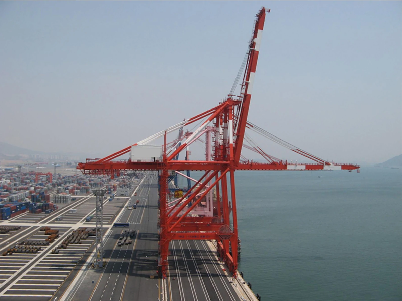
Lift and move vessels through boatyards and marinas.
Explore Marine Travel Lifts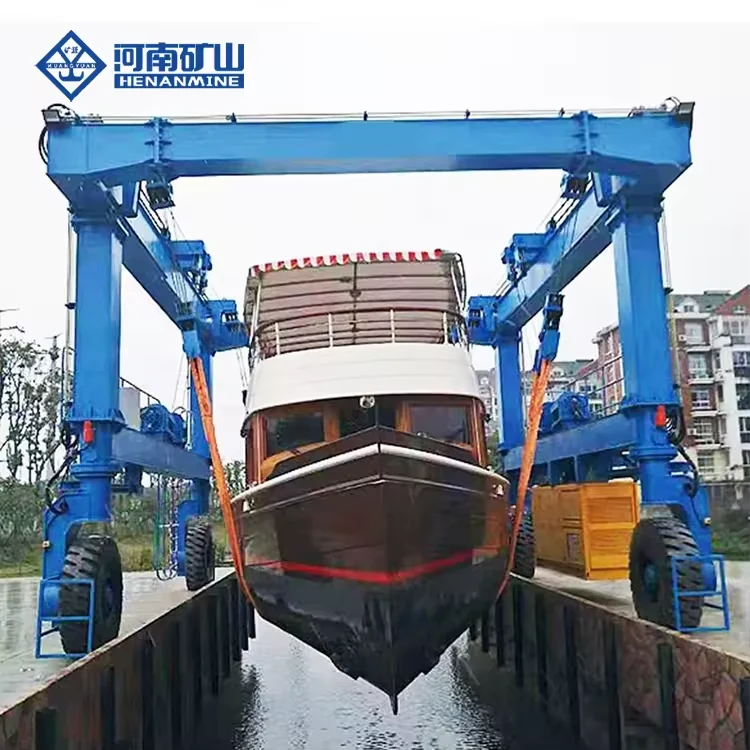
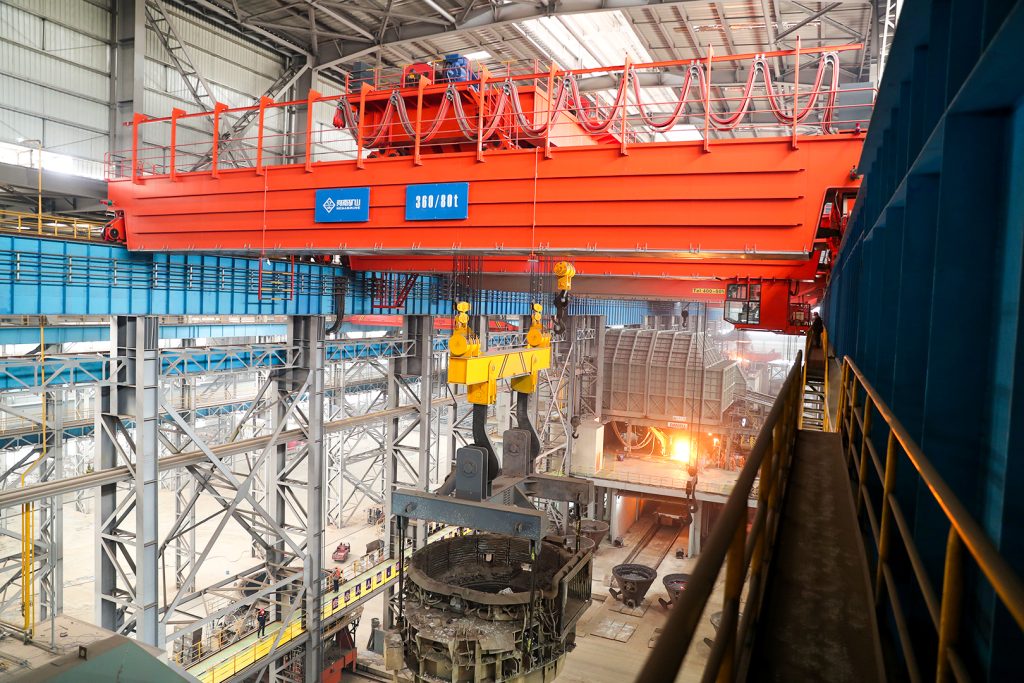
Ladle, slab, scrap and coil handling across steel production.
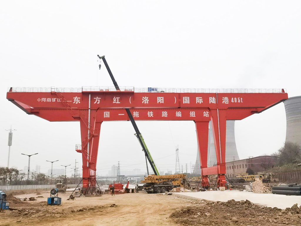
Container stacking and cargo transfers across terminals and rail.
Turbine installation, powerhouse maintenance and wind equipment assembly.
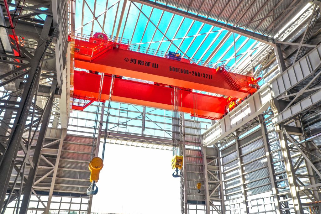
Controlled component transfer and positioning for precision assembly.
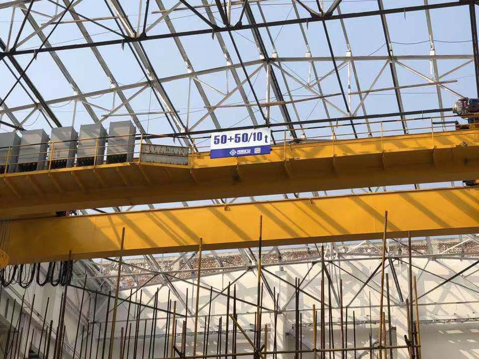
Heavy fabrication, production lifting and factory crane automation.
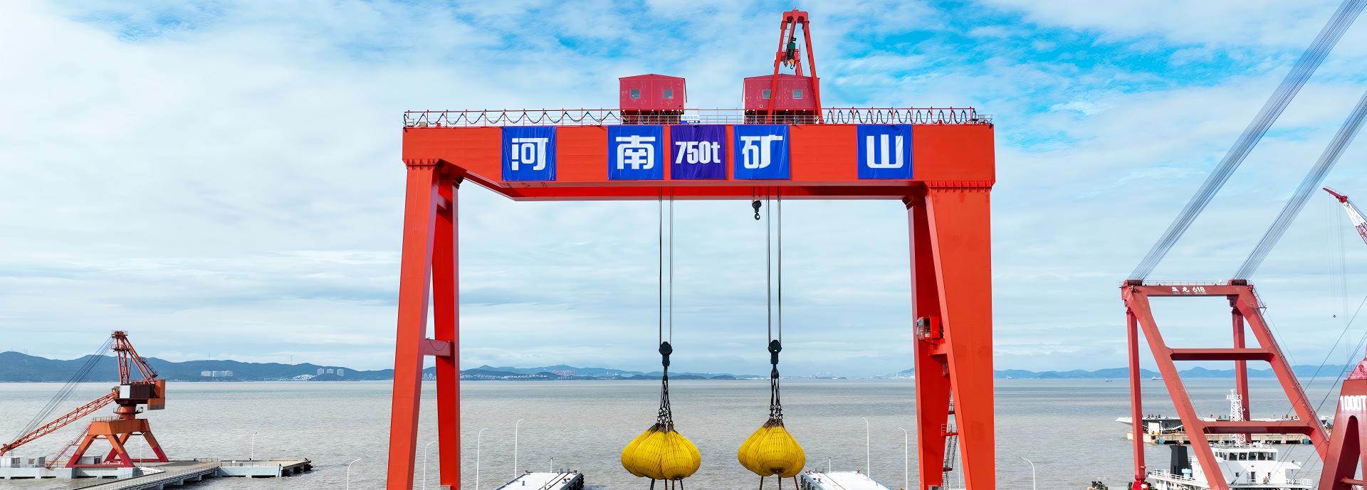
Process lifting for smelters, carbon blocks and anode materials.
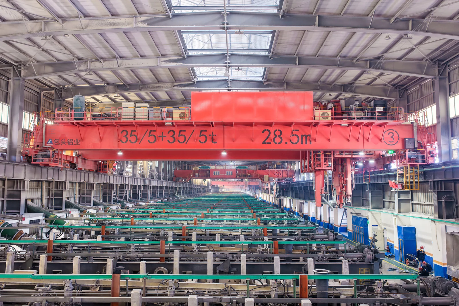
Clean lifting and classified protection for sensitive process areas.
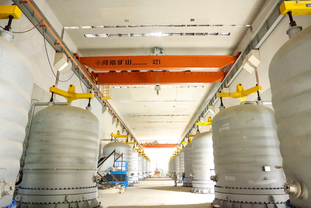
Bridge fabrication, metro construction and ship block assembly.
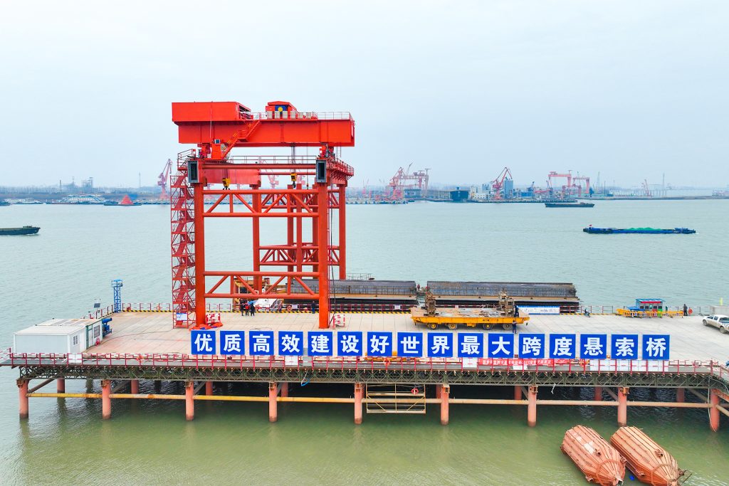
Automated storage and retrieval for plates, cables and bins.
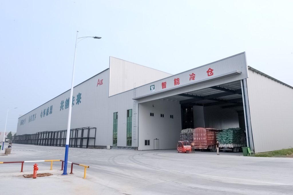
Follow project dispatches, crane engineering and factory acceptance.
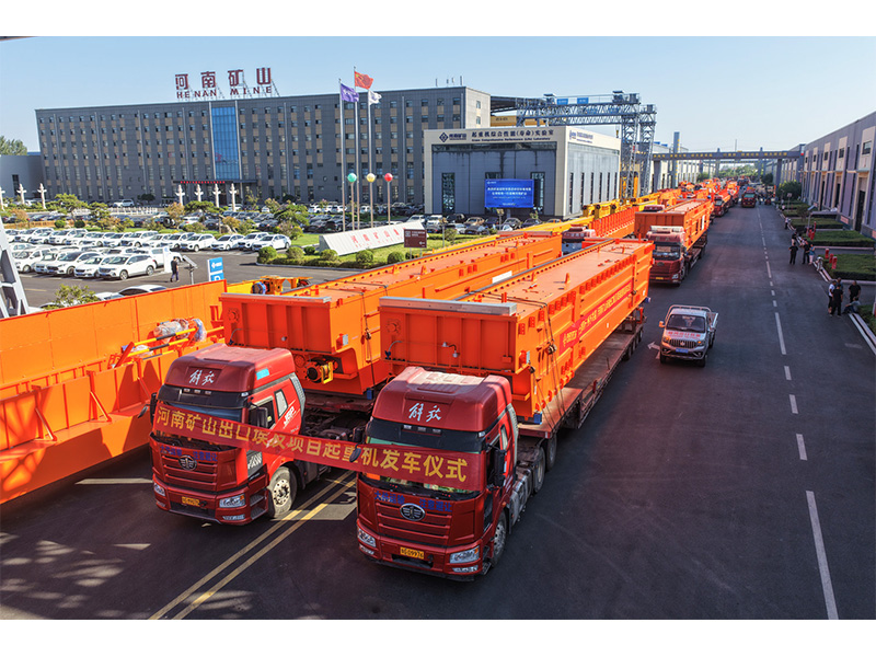
Dispatch, installation and equipment in service
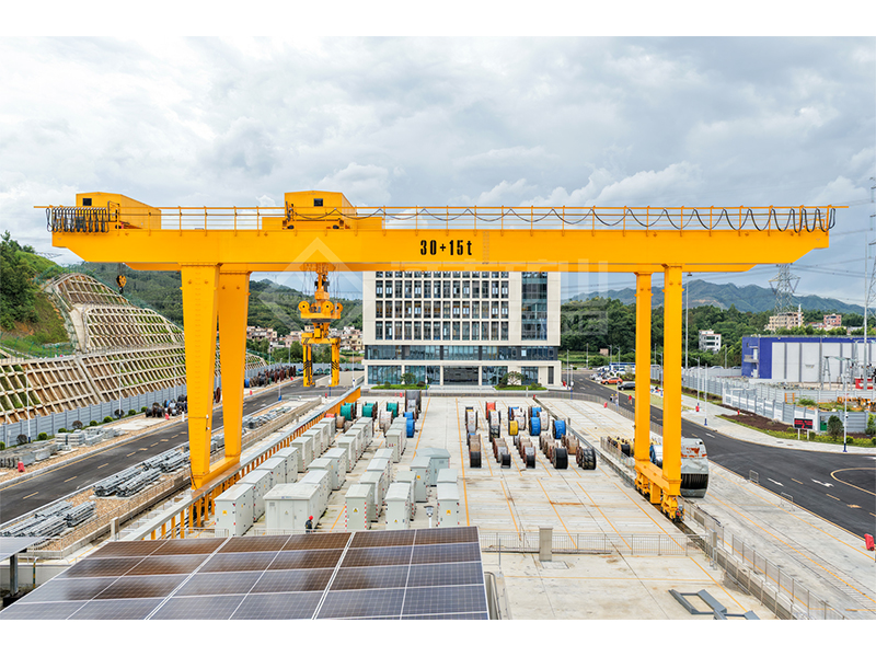
Crane configurations and handling technology
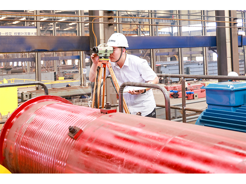
Factory inspections, acceptance and test programmes

Company developments, people and community programmes
Handle aircraft components and large assemblies across a wide production hall. LXD uses a single-girder bridge carried on three or more suspended runways, with coordinated travel drives selected for the working area and lifting cycle.
Share the complete load, total working width and required hook travel. A hall plan or workshop photo helps show the available support layout and lifting positions.
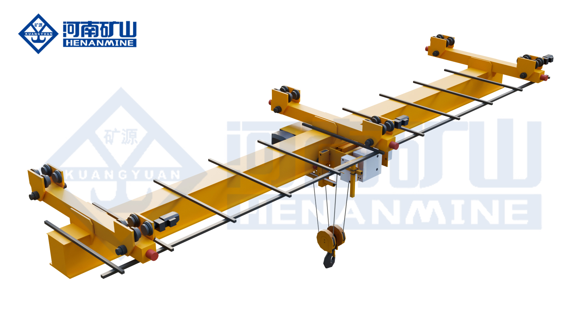
Tell us the overall area the hook must reach. Individual runway spacing is selected separately from the total working width.
Multiple overhead runways support one bridge across a wide working area. Their spacing follows the building and selected crane layout.
Overhead handling leaves the floor available for assembly fixtures, aircraft components, access equipment and material staging.
Coordinated travel drives move the bridge along its multiple suspended runways. Select the motion package for the load, route and frequency of use.

Move aircraft sections, tooling and production equipment between defined positions. Select hook coverage around the assembly stations and access required for the workpiece.
Lift components above aircraft servicing positions while preserving floor space for access stands and tooling. Include the removal path and required upper hook position when planning the working area.
Transfer bulky machinery and fabricated assemblies across a broad work area. Match the load rating, hook travel and motion speeds to the production process and operating shifts.
The 10–60 m figure describes total working width; spacing between suspension runways is set by the selected layout.
Use these series ranges for initial comparison. Capacity, total working width, runway spacing, hook travel and duty form one selected arrangement; range endpoints are not an automatic orderable combination.
| Rated capacity | 1–20 t; custom loads available |
|---|---|
| Total working width | 10–60 m; layout-specific design |
| Lifting height | 6–18 m; custom hook travel available |
| Working class | A3–A6; selected to duty |
| Hoisting speed | 2–12 m/min; speed-control options available |
| Crane travel speed | 15–30 m/min |
| Hoist trolley travel | Configured to span, positioning and handling cycle |
| Suspension supports | 3 or more; quantity to layout |
| Support spacing | Matched to the building grid |
| Travel drive | Coordinated three-in-one drive units |
| Hoist type | Custom electric hoist |
| Control | Ground pendant / wireless remote / cabin |
| Power supply | 380 V, 50 Hz, 3-phase; export supply options |
| Protection | IP54; IP65 option |
| Operating temperature | −25°C to +50°C; matched to environment |
| Bridge structure | Single girder across multiple suspended runways |
| Typical application | Aircraft manufacture, hangars and wide assembly halls |
The installed arrangement shows several suspended runway tracks serving one bridge, with the production area accessible beneath it.
Build the crane package around the positions the load must reach. The working width, suspended runway layout, electric hoist and coordinated travel system are selected together.
Define the required hook coverage from your pickup, transfer and set-down positions. Include the available runway length and obstacles within the hall.
Select the lifting mechanism and working duty from the complete suspended load, lifts per hour and operating shifts. The listed A3–A6 range is matched to the chosen crane configuration.
The bridge uses three or more suspension positions. Their number and spacing are chosen for the working width, crane loads and available building supports.
Match lifting and travel speeds to the production route and placement task. Choose pendant, wireless or cabin control for the operator’s position and view of the load.
Compare a complete wide-hall crane offer, with the bridge equipment, runway scope, delivery and site services identified before ordering.
Request one LXD crane or a package for several working areas. List the load and coverage needed for each crane so every configuration is identified in the offer.
The offer identifies the bridge, electric hoist, coordinated travel drives, controls and power feed. Ask for suspended runways, hangers, packing, freight and installation services to be shown separately.
State the destination and required standards. The offer identifies the arrangement and electrical drawings, operating and maintenance documents, inspection records and applicable conformity documents for the selected equipment.
Production lead time and planned dispatch are confirmed for the chosen LXD arrangement. Schedule freight, runway preparation and site installation separately around your hall programme.
Include the installation location and site schedule in your enquiry. The quotation defines any installation guidance, commissioning assistance or site support, with the agreed responsibilities and costs.
Confirm the warranty period, start date and coverage in the offer. Ask for the recommended spare-parts package and service arrangements for the electric hoist and coordinated travel equipment.
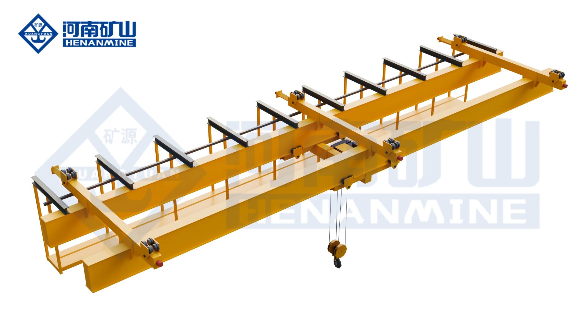
A double-girder electric-hoist bridge carried at multiple suspension points. Choose the complete bridge, hoist and support layout together for broad workshop coverage.
Compare this arrangement ↗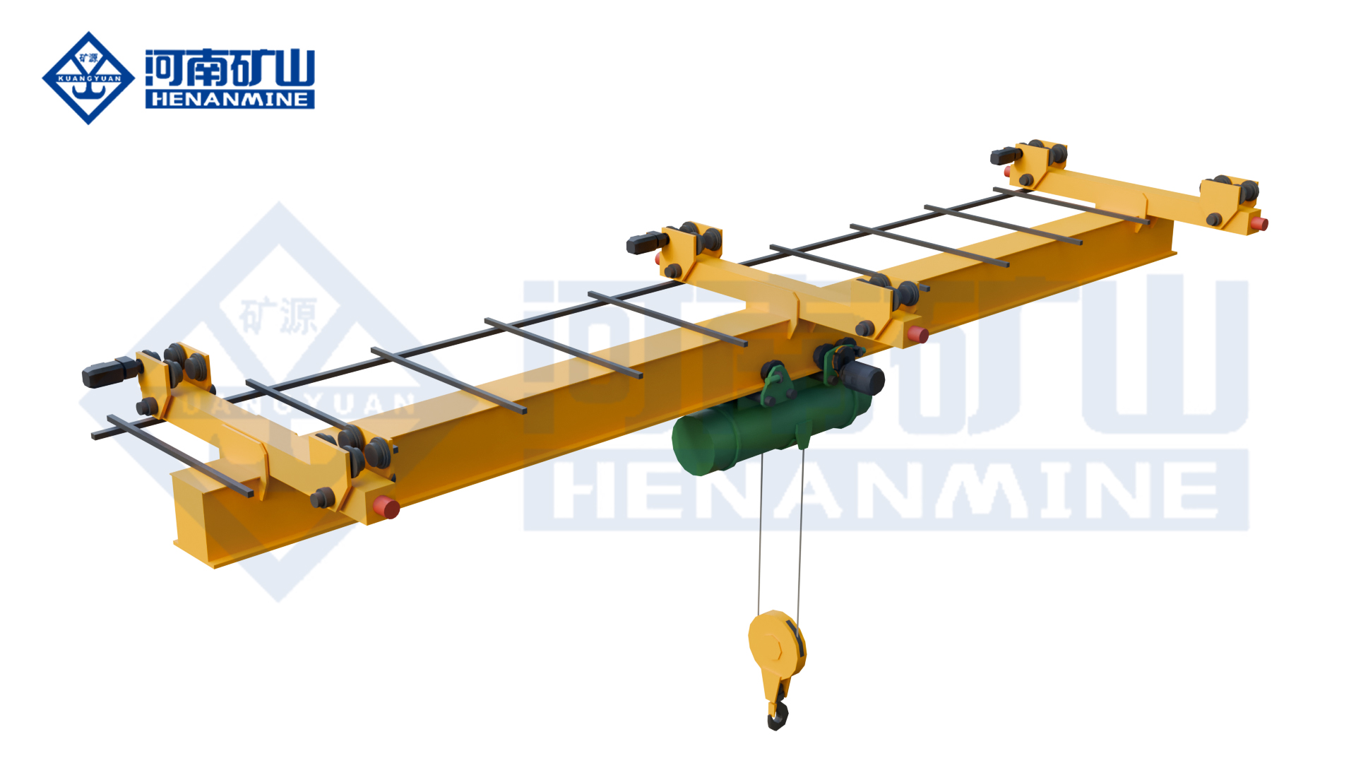
Protected multi-point suspended lifting for wide classified workshops. Match the hoist and travel package to the area classification.
Compare this arrangement ↗
Underhung single-girder lifting for components and equipment within one workshop bay.
Compare this arrangement ↗Understand working width, support spacing and the complete supply package before choosing your wide-hall crane.
Consider LXD when your required hook coverage extends across a wide hall with several overhead support lines. Its multi-runway arrangement can serve aircraft manufacturing, hangars and large assembly areas; the layout is selected for the load and building.
No. It describes the total working width of the crane arrangement. Individual runway spacing and bridge overhangs are defined separately in the crane layout.
These are series ranges rather than a standard 20 t by 60 m package. The offer confirms a matched capacity, total working width, hook travel, support arrangement and duty for your application.
Series options include 6–18 m lifting height, 2–12 m/min lifting speed and 15–30 m/min crane travel. Hoist cross travel, controls and power supply are configured for the selected handling cycle.
The offer identifies the bridge and lifting equipment, travel drives, electrical package, packing and any runway supply. Installation guidance, commissioning assistance and recommended spares are included where agreed in the quoted scope.
State your destination, required standards and target installation date. The offer lists the applicable conformity documents, production lead time, delivery basis and warranty period and coverage for the chosen crane.
Existing supports may be suitable, but their locations, connections and allowable loads need to match the crane arrangement. Start with the building grid and any available support information. The final proposal identifies the runway interfaces and crane reactions for the selected design.
Give the heaviest component weight together with the weight of lifting beams, slings or other attachments. Also describe the usual loads, lifting frequency, working shifts and placement task so the hoist and crane duty can be selected for the actual operation.
Send the complete load, total working area and required hook travel, plus your project location. Include a hall plan or support-grid sketch if available so the crane can be configured around your lifting positions.
info@cranehenanmine.com