
Skip to content
Henan mine crane co., ltd. Get a project quote
MBES / Electric-hoist lifting configurations

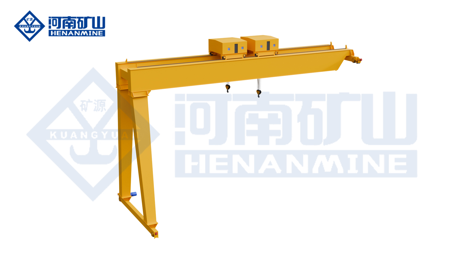
MBES New-Design Double-Girder Electric Hoist Semi-Gantry Crane

MBES combines a new-design double-girder bridge and top-running electric-hoist trolley with a semi-gantry support layout. One side follows an elevated runway; the other runs on a ground rail. Compare its compact envelope, direct-connected travel drives and pendant or remote operation with workshop clearances and operator visibility.

Structure
New-design double-girder semi-gantry
Trolley
Top-running electric-hoist trolley
Runway
One elevated runway and one ground rail
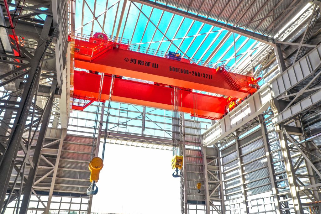
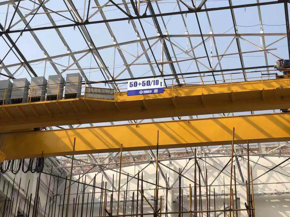
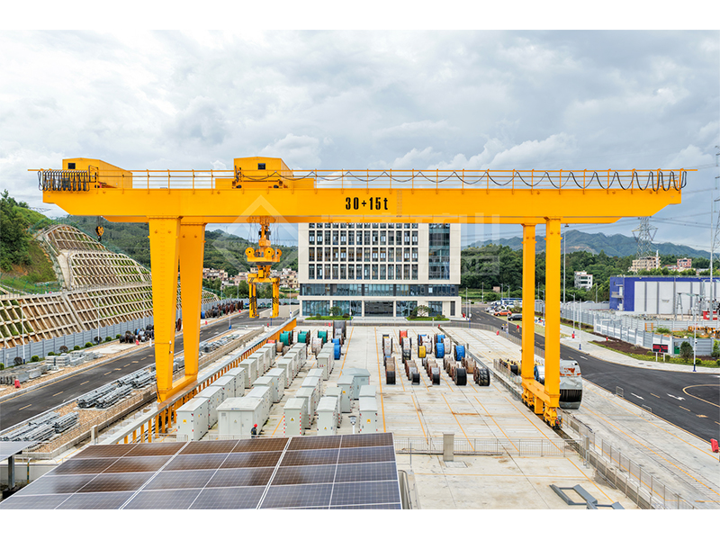
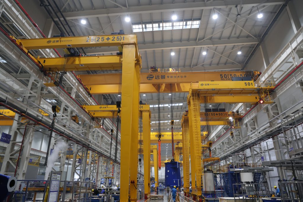
Factory-listed double-girder electric-hoist semi-gantry cranes in a workshop
Double-girder semi-gantry arrangement in a workshop — series photograph.Equipment application photograph
01 / APPLICATIONS

Where the MBES
fits the work.

01

Equipment and component assembly

Move assemblies, fixtures and equipment sections between preparation and fitting positions. The double-girder trolley layout can be assessed around the required hook position and the clearances available above the workpiece.

02

Workshop-to-storage handling

Connect production support positions with adjacent storage along one runway route. The semi-gantry layout serves the strip between the elevated supporting side and the ground-side travel corridor used by the leg.

03

Constrained production support areas

Handle tooling and rigged components where building columns, services and nearby equipment limit the installation envelope. The compact crane arrangement is useful only when the complete bridge, trolley and travel path fit.

02 / TECHNICAL SPECIFICATIONS

MBES specifications
and equipment configuration.

Compare the lifting mechanism, control functions and site interfaces for the selected crane.

Select the top-running electric-hoist package with both runway levels, hook clearance and supporting reactions. The A3–A5 range requires a class selected for the actual operating cycle.

MBES technical specifications and configuration
ModelMBESRated lifting capacitySelected for the complete suspended load, including rigging
SpanRail-centre span selected for the working areaLifting heightHook travel and headroom selected for pickup / set-down levels
Girder arrangementDouble girderRunway/support layoutSemi-gantry; one elevated runway and one ground rail
Lifting mechanismElectric hoistHoist/trolley arrangementTop-running electric-hoist trolley
Lifting attachmentHook / grab / electromagnetic lifting configurationsWorking classA3–A5
Lifting speedLifting and positioning speeds matched to the selected electric hoistTrolley travel speedCross-travel speed and stopping control selected for the load route
Crane travel speedLong-travel speed selected for the runway and operating cycleTravel drive / motion controlThree-in-one direct-connected crane and trolley travel drives
Operating controlsPendant / wireless remote optionsCantilever arrangementWith or without cantilever
Electrical supplySite voltage, phases, frequency and power feed matched in the electrical packageElectrical protectionCabinet, motor and connector protection selected for the environment
Runway rail profileRail section matched to wheel geometry, reactions and supporting structureMotor ratingsLifting, trolley and crane-travel motor ratings specified in the equipment schedule
Operating patternIntermittent, repeated loading/unloading and material handlingSite layoutOverall height, leg clearance and hook approach shown in the crane drawing
03 / EQUIPMENT VIEWS

See the MBES arrangement.

Review the original equipment views alongside the selected crane drawing.

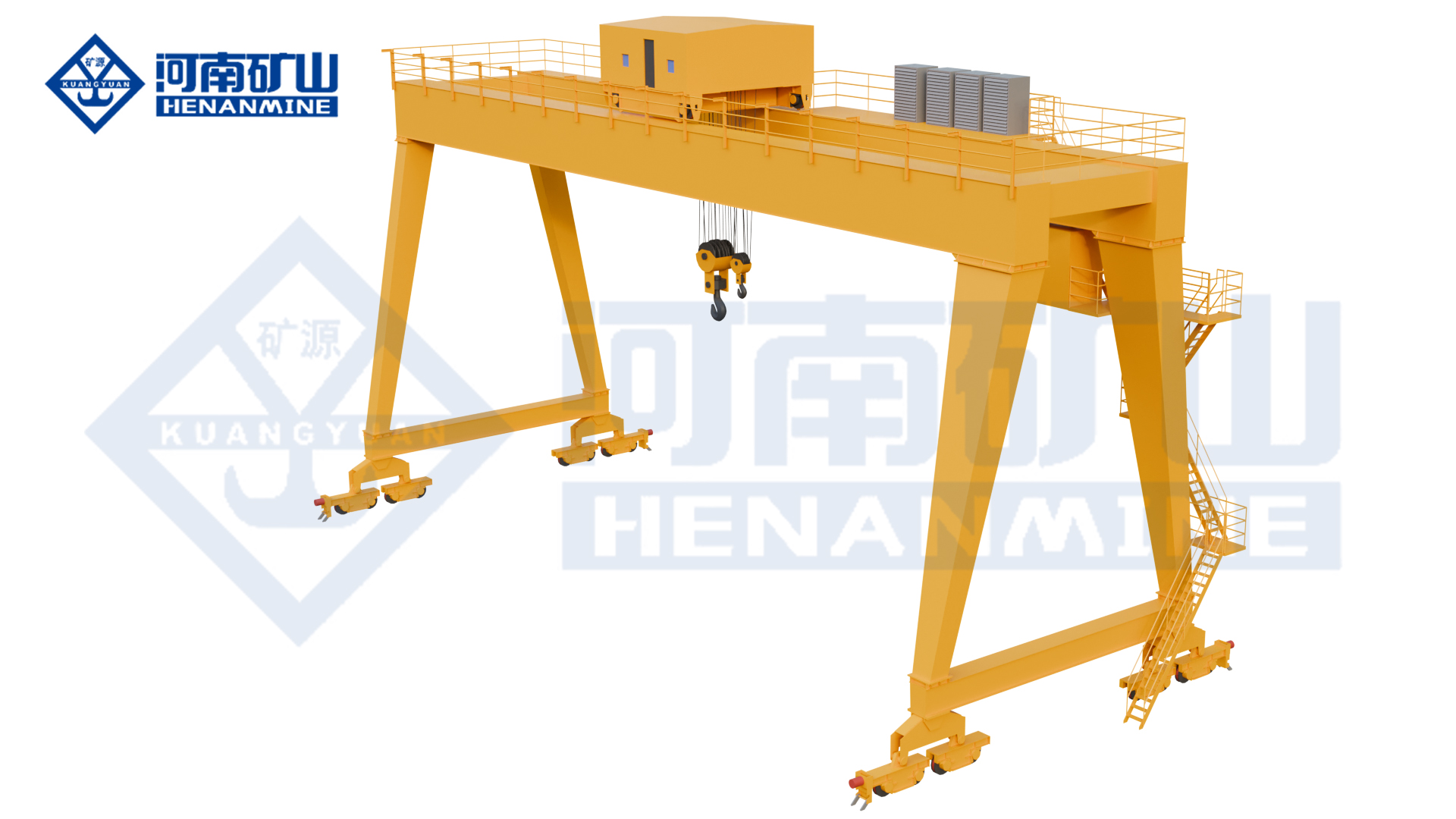
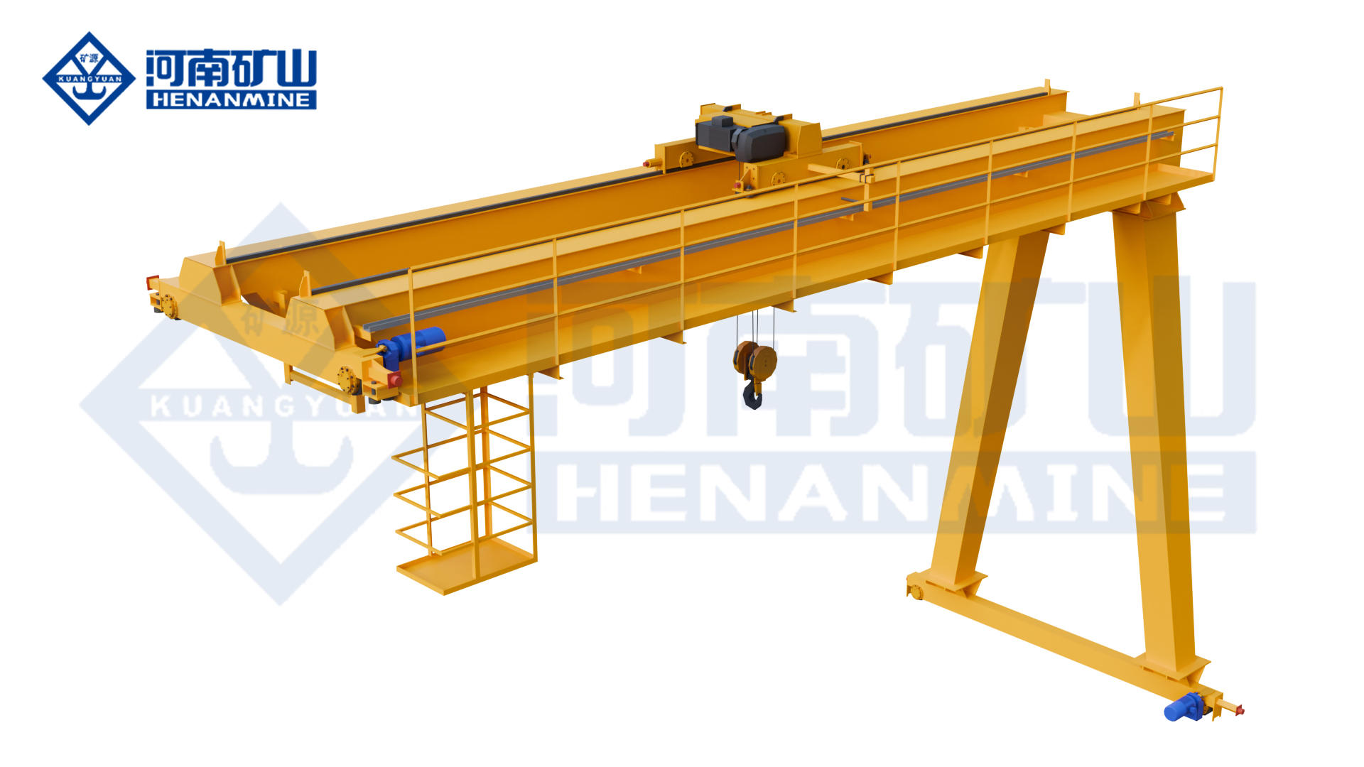
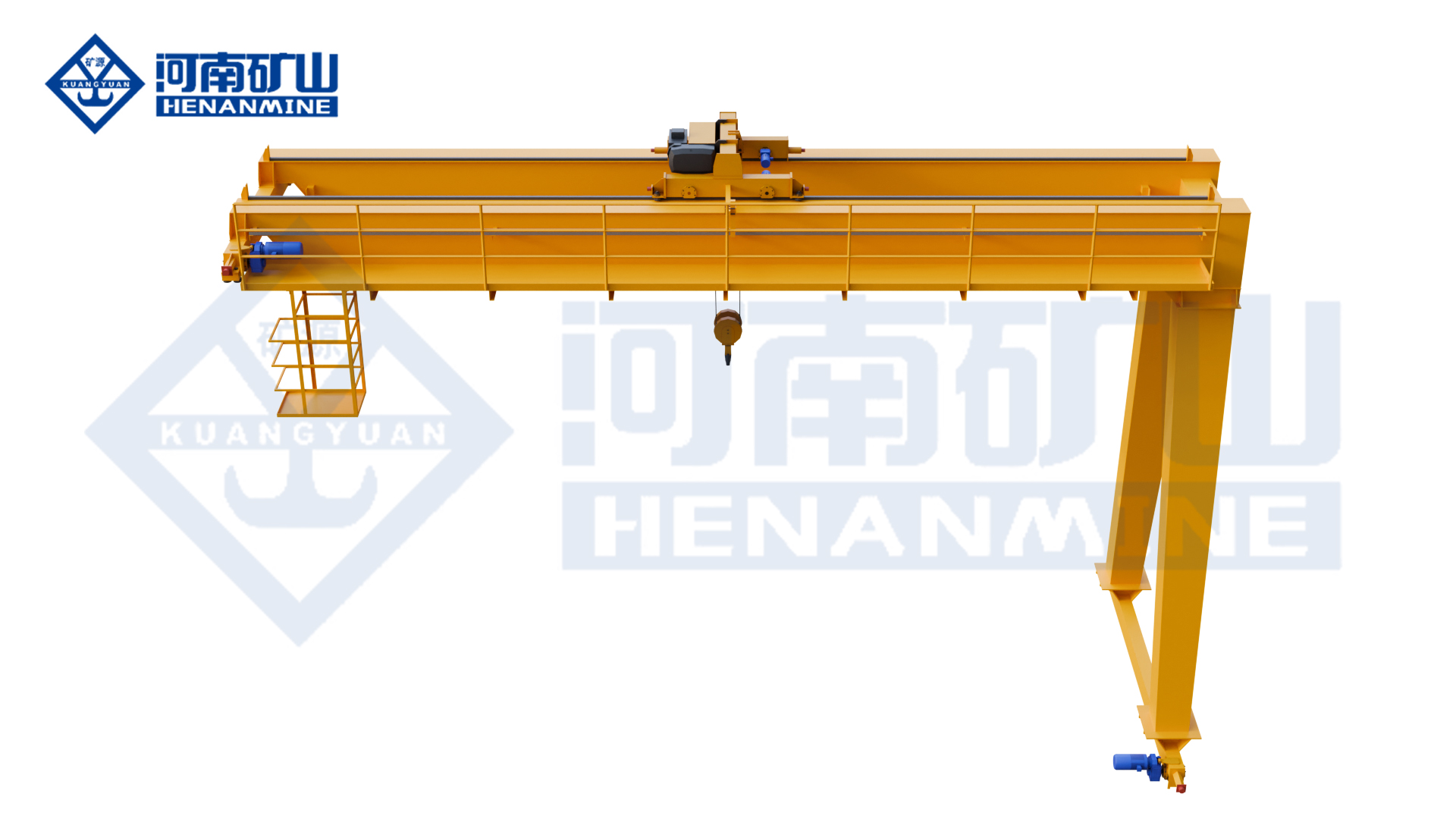
Manufacturer rendering: Three-quarter view of the new-design double-girder semi-gantry
Three-quarter view of the new-design double-girder semi-gantry — manufacturer rendering.
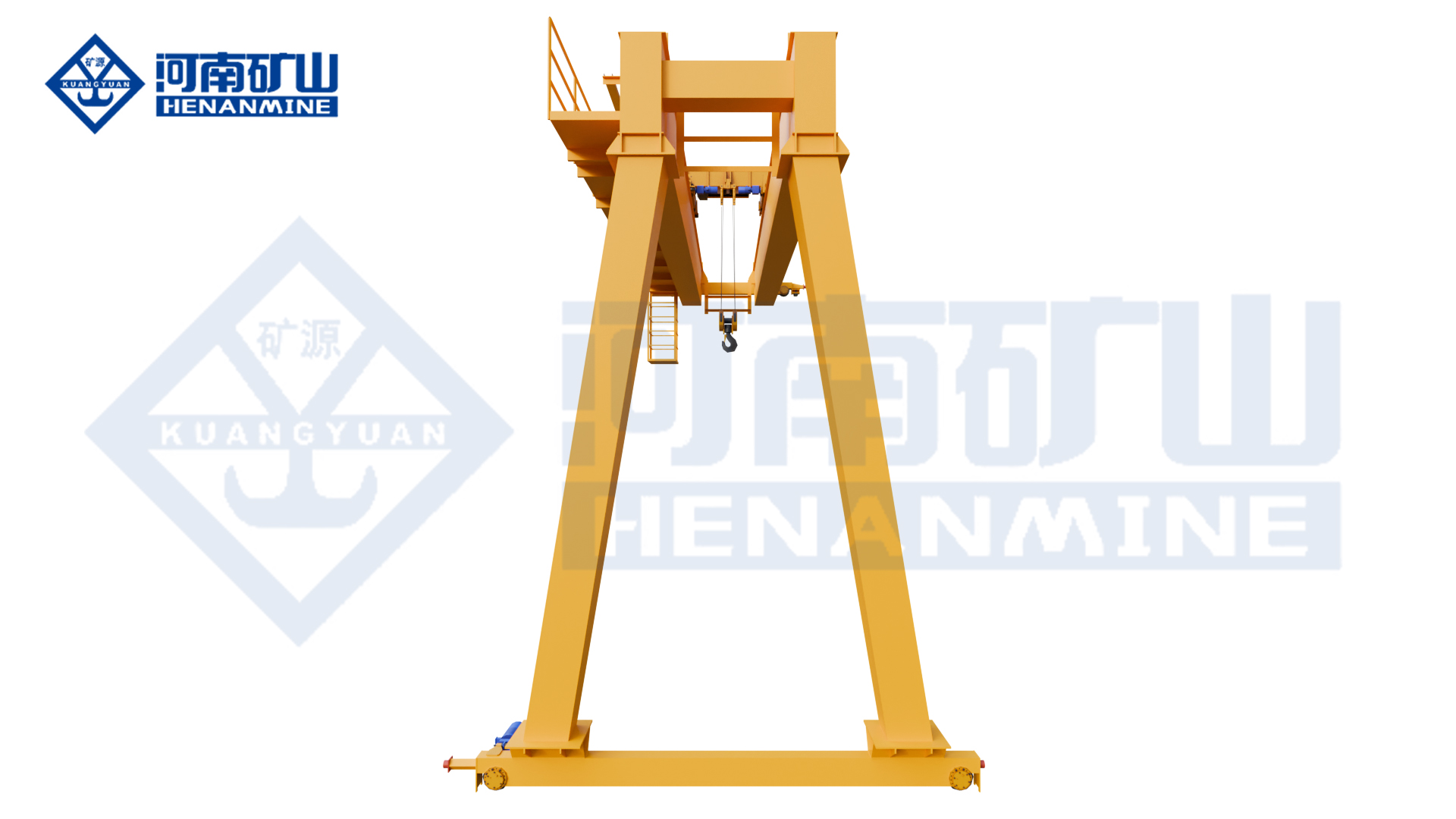
Manufacturer rendering: Front view of the new-design double-girder semi-gantry
Front view of the new-design double-girder semi-gantry — manufacturer rendering.
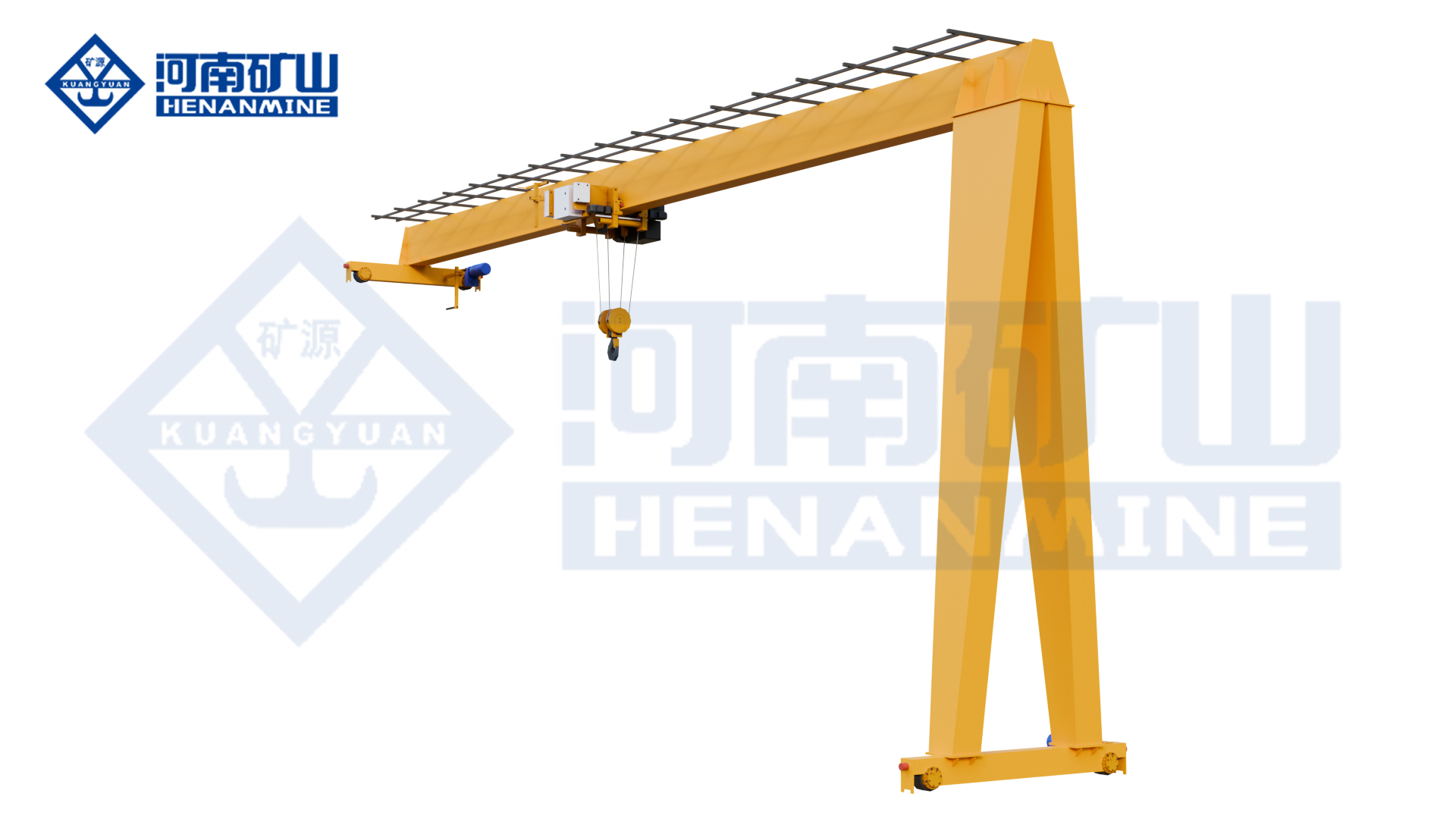
Manufacturer rendering: End view showing the double-girder semi-gantry arrangement
End view showing the double-girder semi-gantry arrangement — manufacturer rendering.
04 / CONFIGURATION

Choose the MBES equipment and site interfaces.

01 / OPTION

Trolley, load and duty

Select the top-running electric-hoist trolley, hook or grab/electromagnetic attachment for complete suspended mass, hook travel and placement. Match A3–A5 to load spectrum, repeated operation and attachment-specific mechanism and electrical requirements.

02 / OPTION

Bridge and support envelope

Compare overall bridge and trolley height with useful hook position and approaches. One end uses an elevated runway, the other a ground rail; both supports must suit selected vertical and horizontal reactions. Compact construction does not make overall height equal hook travel.

03 / OPTION

Coverage, drives and controls

Define any cantilever pickup point and allowed load. Crane and trolley use direct-connected three-in-one drives; pendant and wireless remote control support the operator-led sequence. Specify attachment connections, electrical functions and equipment protection for the environment.

04 / OPTION

Floor route and service access

Show both rail levels, pickup and landing positions, vehicle and pedestrian routes and stopped-crane positions. Keep the ground-side travelling-leg corridor and maintenance access to the trolley and drives clear; assess surrounding structure throughout the load route.

05 / PURCHASING & DELIVERY

Confirm the complete MBES supply scope.

ORDER

Order quantity

Enquire for one complete crane or your project quantity. Start with the load, approximate rail-centre span, useful lifting height and destination. Unknown dimensions can remain open; runway levels, support information and the final equipment arrangement can be developed with the proposal.

QUOTATION

Equipment and quotation scope

The offer should identify the selected hoist, trolley, drives, attachment and controls, then state the scope for elevated runway equipment, ground rails and foundations, power feed, packing, freight, installation and commissioning. Price, delivery schedule and service terms are confirmed for the chosen package.

DOCUMENTS

Drawings and equipment documents

The equipment drawing should resolve overall height, upper hook position, approaches and both runway reactions for the proposed MBES arrangement.

ACCEPTANCE

Standards and acceptance

Agree destination standards and model-specific equipment documents with inspection and acceptance tests appropriate to the selected hoist and attachment.

DELIVERY

Delivery and installation

Plan bridge and trolley delivery around access to the existing workshop and the sequence for preparing both supporting runways.

SUPPORT

Warranty and spare parts

Confirm installation responsibilities, commissioning support and delivery dates in the order, together with warranty terms, maintenance instructions and spare-parts support.

CONTINUE YOUR COMPARISON

Compare related
gantry arrangements.

All 5 semi-gantry models ↗
07 / QUESTIONS BEFORE ORDERING

Choose the MBES
with the job in view.

Compare the handling task, selected lifting equipment and supply scope before ordering.

What distinguishes MBES from MB₁?

Both are double-girder electric-hoist semi-gantries. MBES is the new-design arrangement, with a focus on compact overall layout, three-in-one travel drives and pendant or remote operation.

Does the compact design guarantee a fit under a low roof?

The highest required hook position, bridge depth and top-running trolley all use part of the available building height. Rigging and the workpiece also need clearance, so the complete layout determines suitability.

Can MBES use the same specification as the single-girder KSMB?

The two models have different bridge and hoist arrangements. KSMB uses a single girder with a suspended hoist, while MBES uses a double-girder trolley arrangement.

Can MBES handle both rigged loads and loose material?

Hook and grab configurations address those different tasks, with electromagnetic lifting also available for compatible material. A mixed handling requirement changes attachment mass, electrical functions and the load spectrum.

When does a cantilever add useful coverage?

A cantilever is useful when a pickup or landing point sits beyond the supporting side of the main working strip. Its practical reach depends on hook approach, leg clearance and nearby structures.

Which operator controls are available for MBES?

Pendant and wireless remote arrangements support operator-led handling along the working strip. Select the observation position around pickup and landing points, nearby activity and the ground-side leg's travel route.

Can the crane use an existing building-side support?

An existing support can be considered after its beam, connections and foundations are checked against the selected crane reactions and duty. Its location and rail profile alone do not establish compatibility.

Does new-design mean faster lifting or a higher duty class?

The new-design label identifies the arrangement. Actual lifting speeds, travel performance and working duty come from the selected MBES hoist and drive package, assessed for the complete load and handling cycle.

08 / YOUR MBES GANTRY PROJECT

Get a quotation
for your MBES crane.

Tell us what you lift, the approximate span, the required lifting height and your destination. If a dimension is unknown, describe the task and leave that field open.

  • An arrangement matched to the lifting task
  • A clear equipment and service scope
  • Delivery and support terms in the offer

info@cranehenanmine.com

PRODUCT SELECTEDMBES New-Design Double-Girder Electric Hoist Semi-Gantry Crane

Not sure about a dimension? Leave it blank. A site sketch is helpful when available.

MBES gantry craneDiscuss your lifting task
Request a quote ↗
MBES equipment gallery
Enlarged MBES crane image

↑