
Power-plant coal-mill maintenance
Lift and move equipment for coal-mill servicing using the dedicated suspended route. Select pickup height and service position around the actual mill and removable components.
Bridge cranes for workshops and production lines.
Explore Overhead Cranes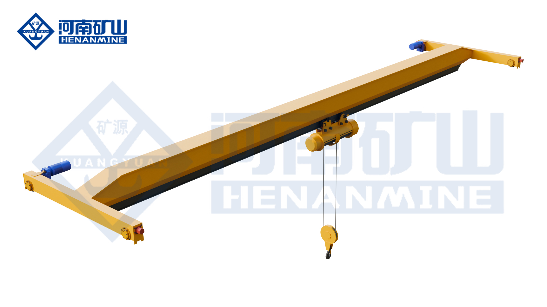
Ground-supported lifting for yards and construction.
Explore Gantry Cranes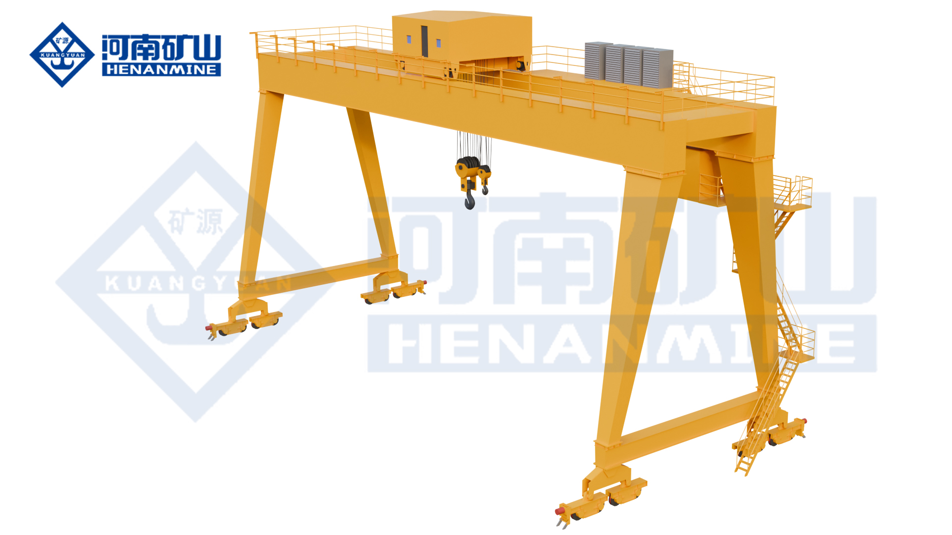
Wire rope and chain hoists for lifting points and cranes.
Explore Electric Hoists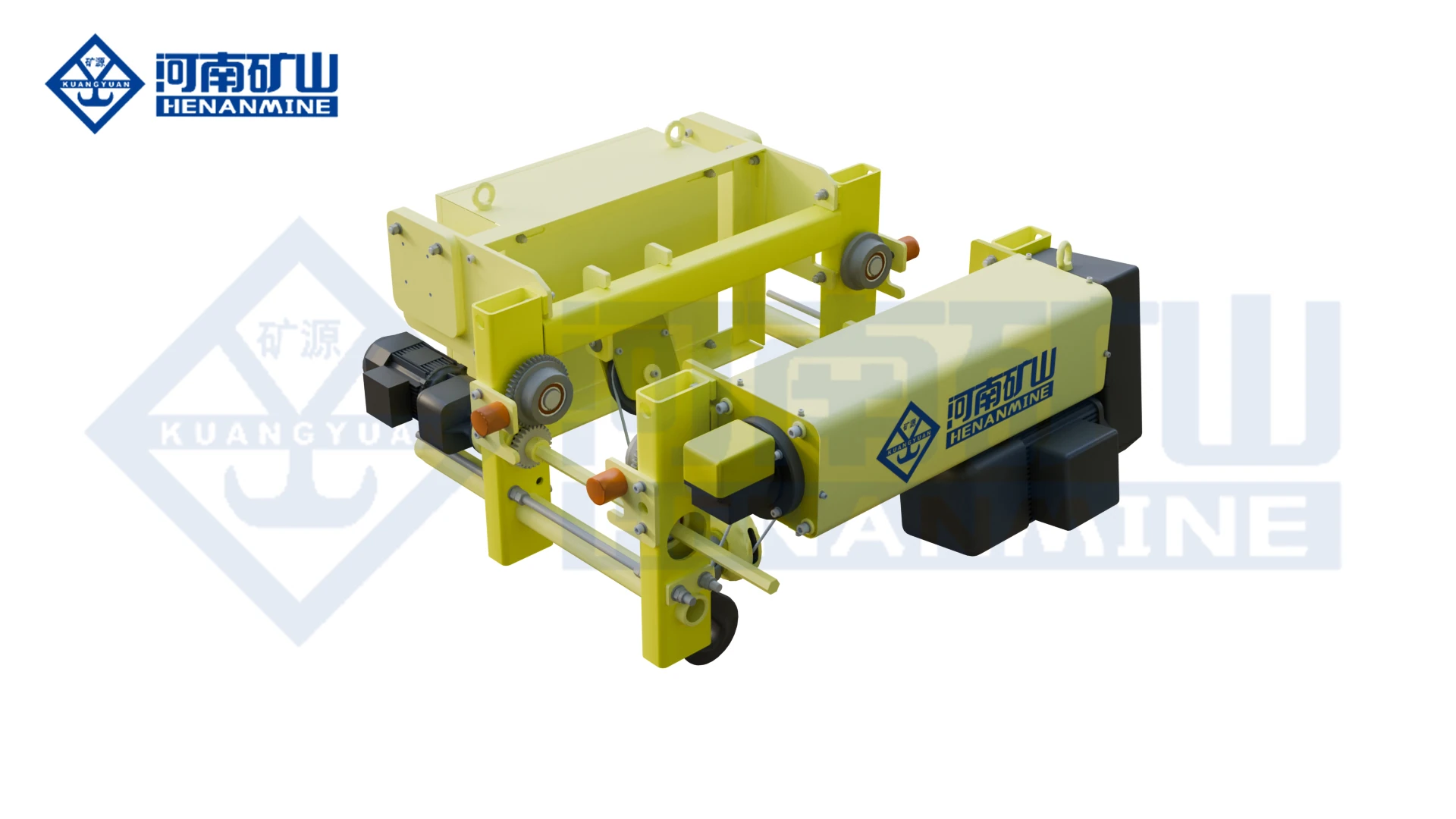
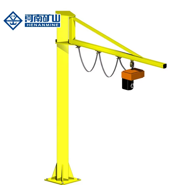
Wire rope lifting and pulling with a powered drum.
Explore Electric Winches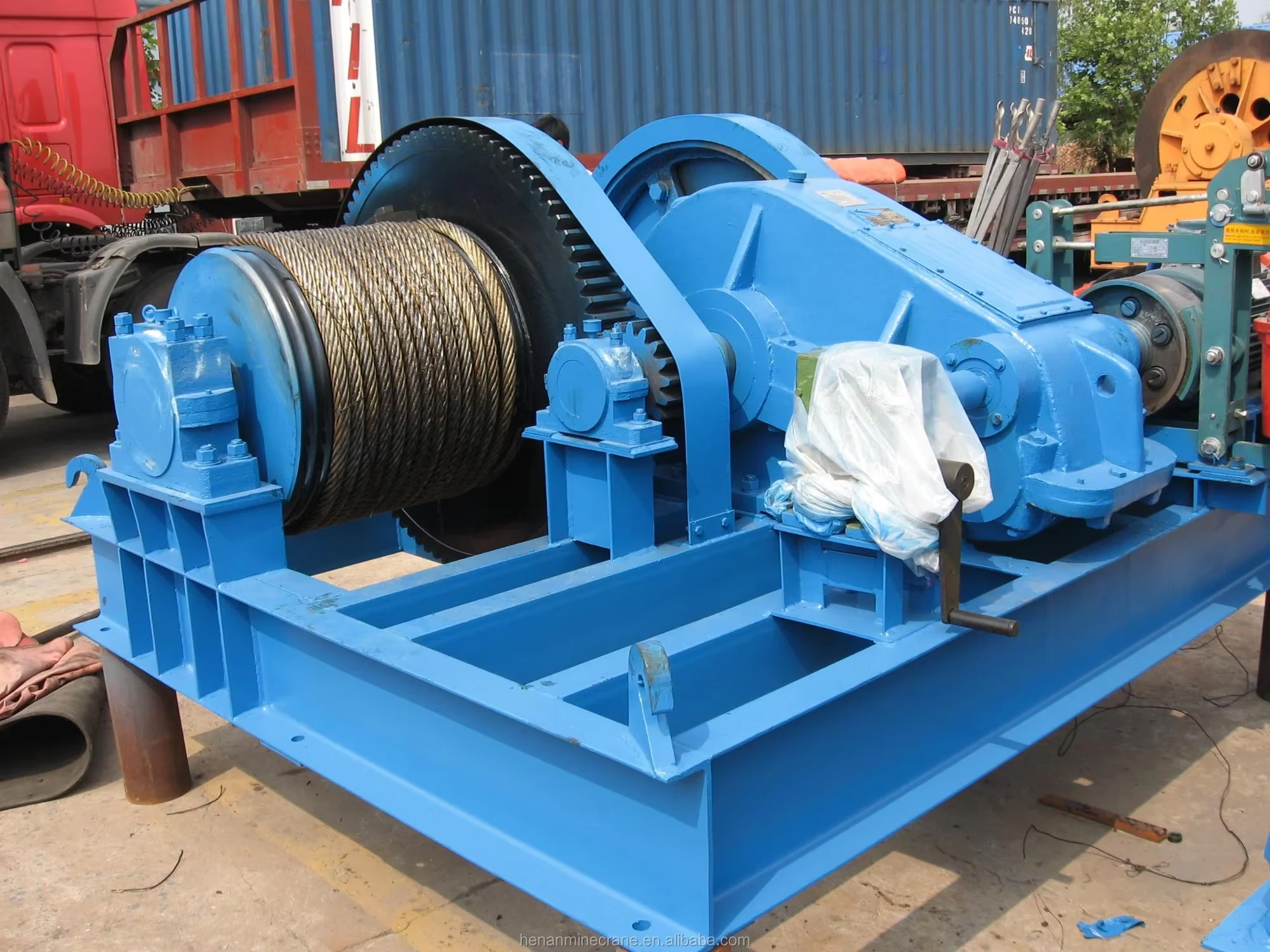
Grab buckets, magnets and hooks for your load.
Explore Lifting Attachments & Grabs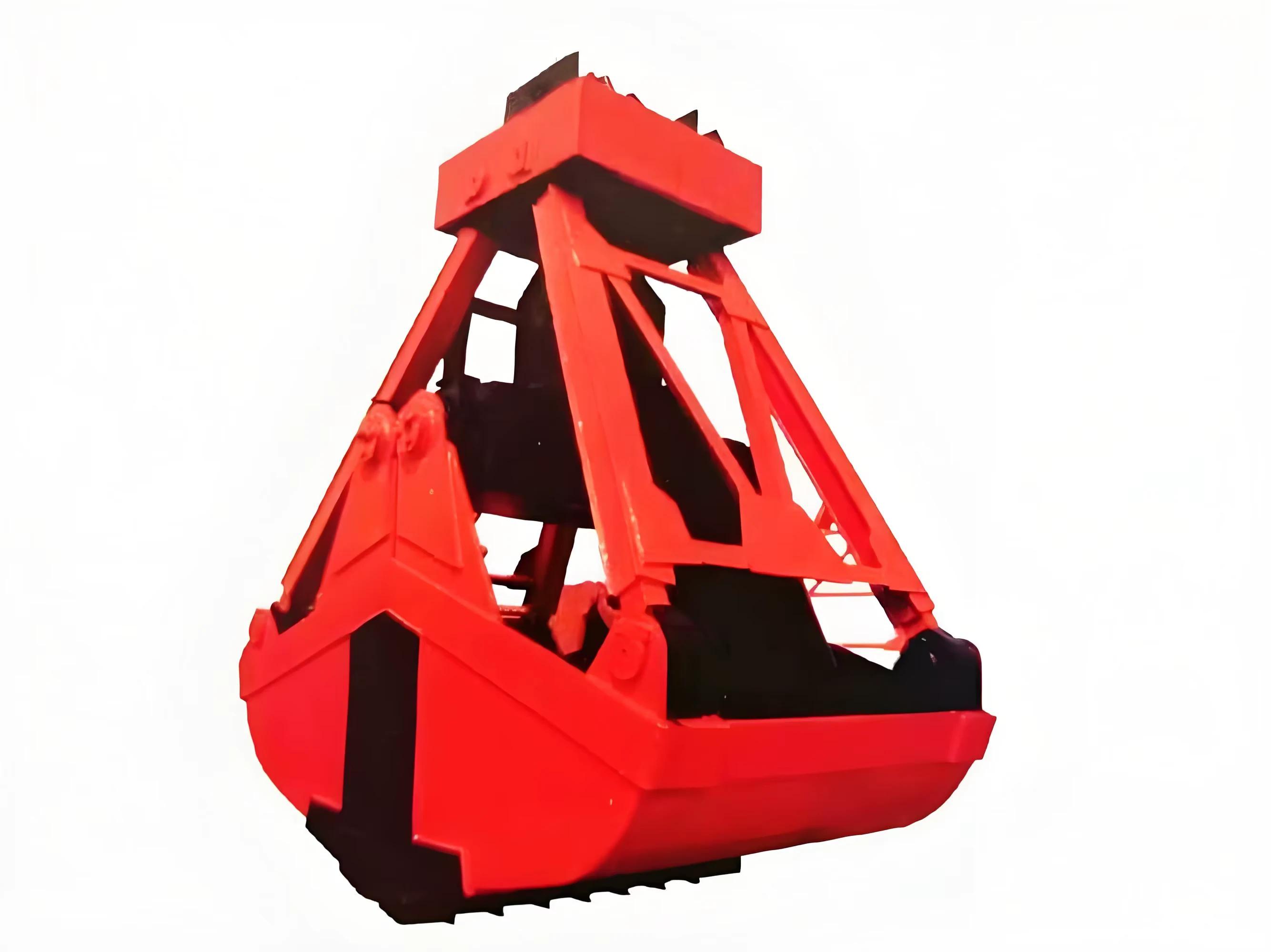
Mobile handling for containers, precast and yard loads.
Explore Rubber-Tired Gantry Cranes & Straddle Carriers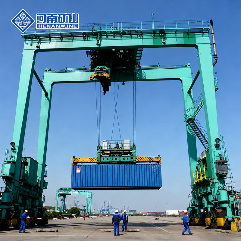
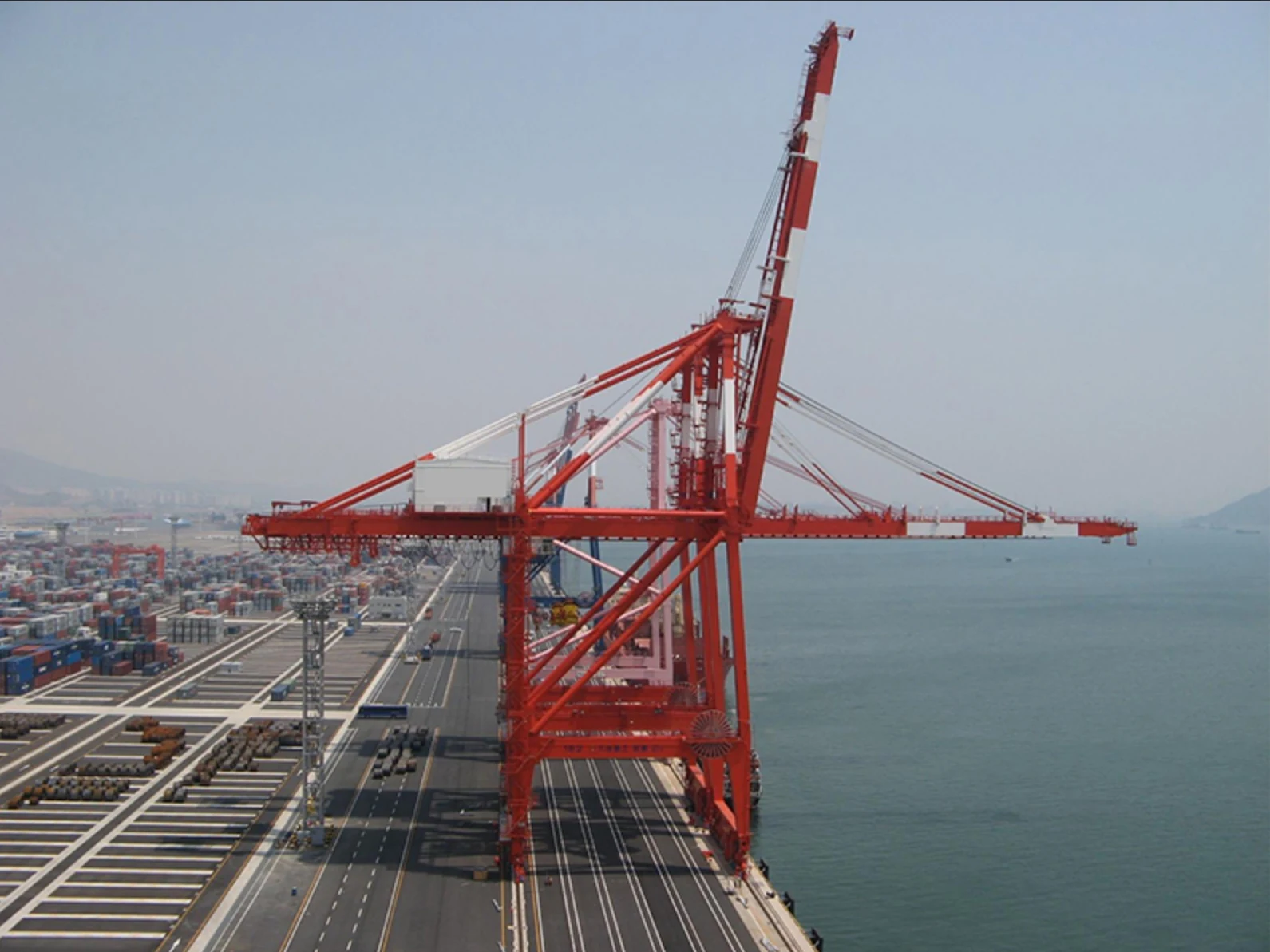
Lift and move vessels through boatyards and marinas.
Explore Marine Travel Lifts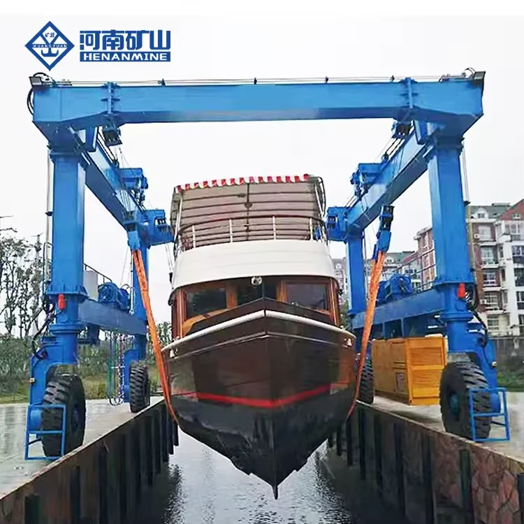
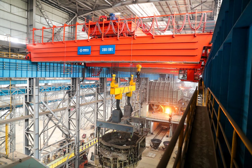
Ladle, slab, scrap and coil handling across steel production.
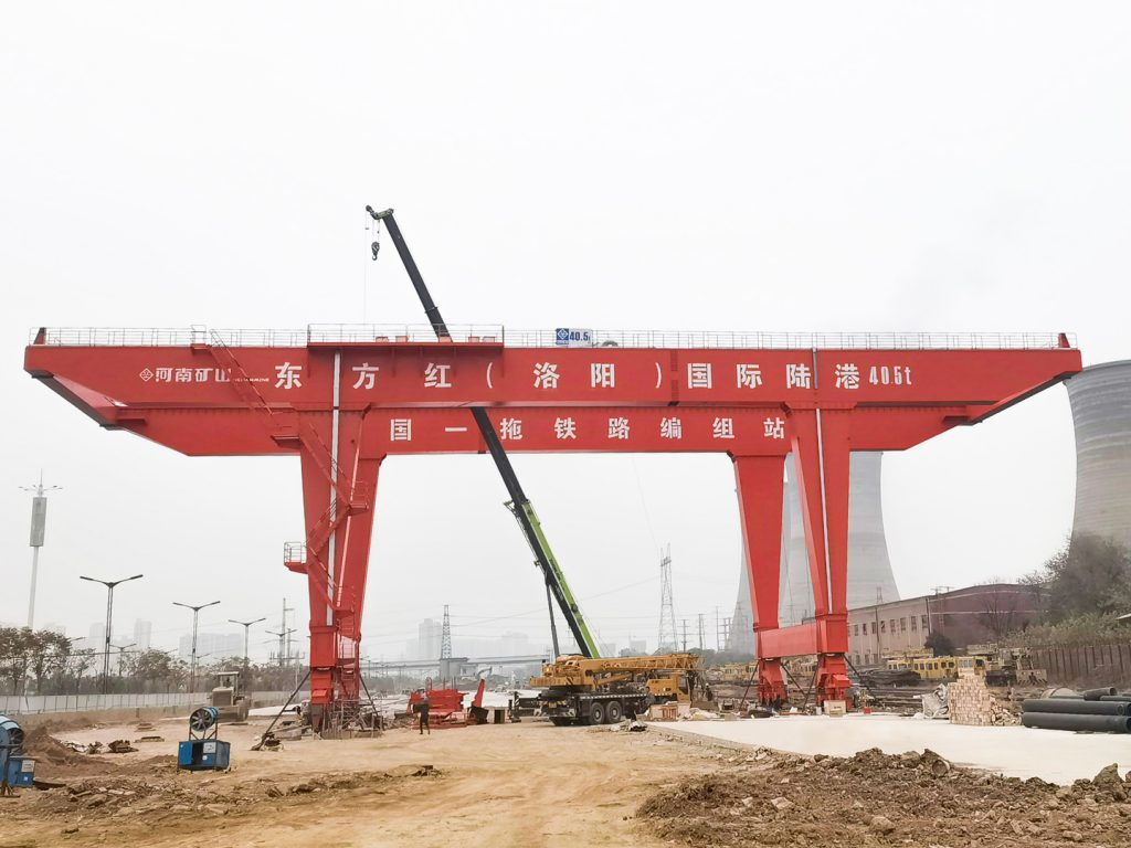
Container stacking and cargo transfers across terminals and rail.
Turbine installation, powerhouse maintenance and wind equipment assembly.
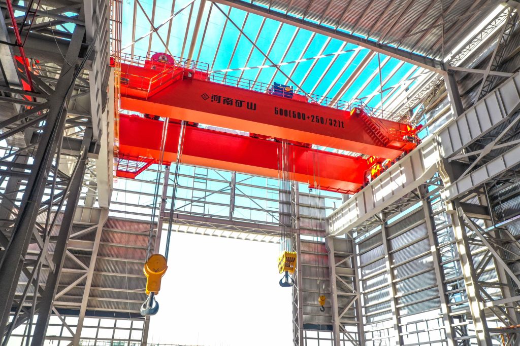
Controlled component transfer and positioning for precision assembly.
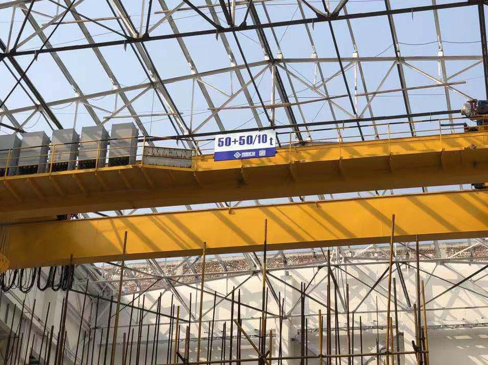
Heavy fabrication, production lifting and factory crane automation.
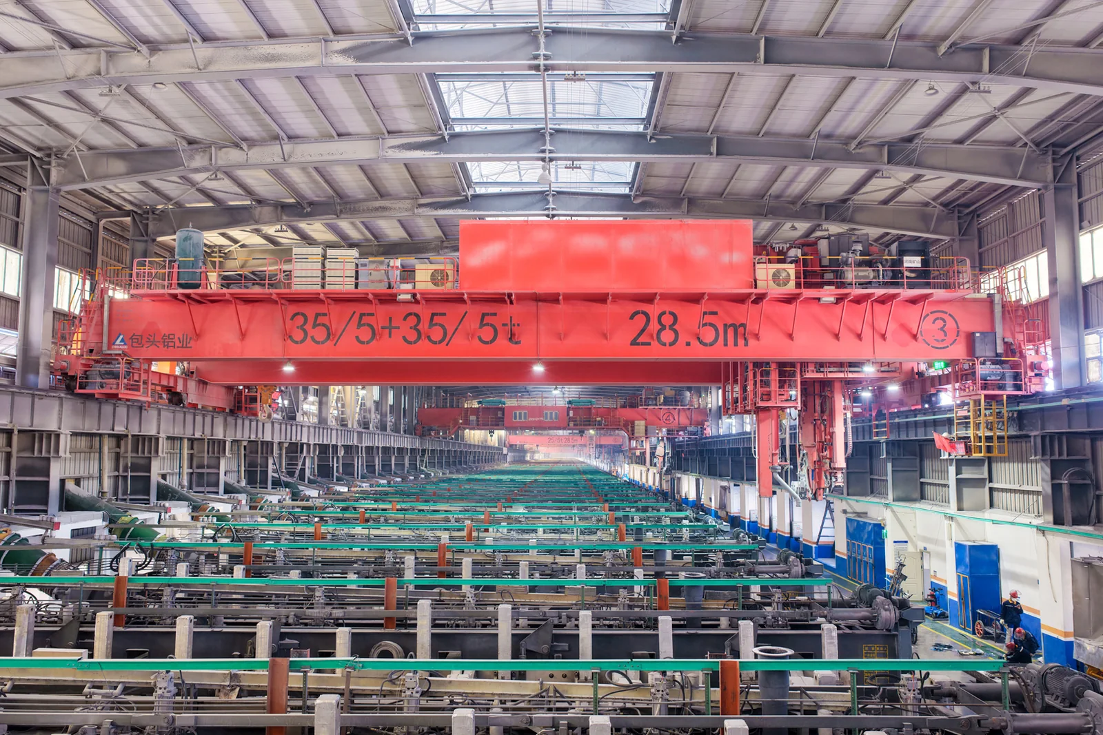
Process lifting for smelters, carbon blocks and anode materials.
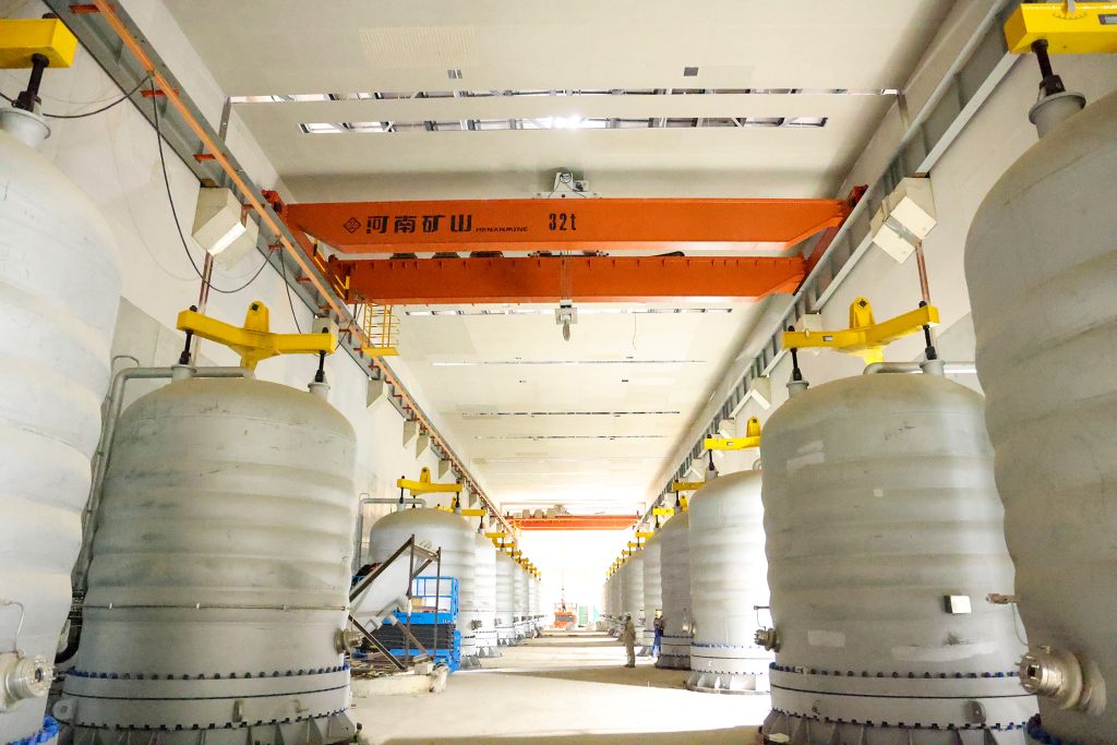
Clean lifting and classified protection for sensitive process areas.
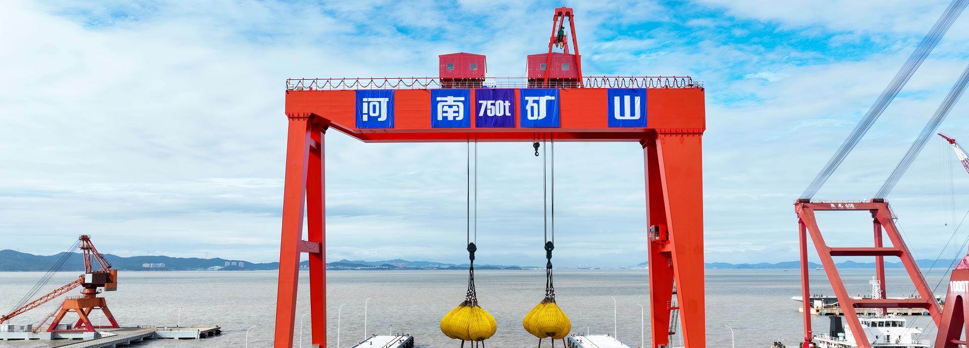
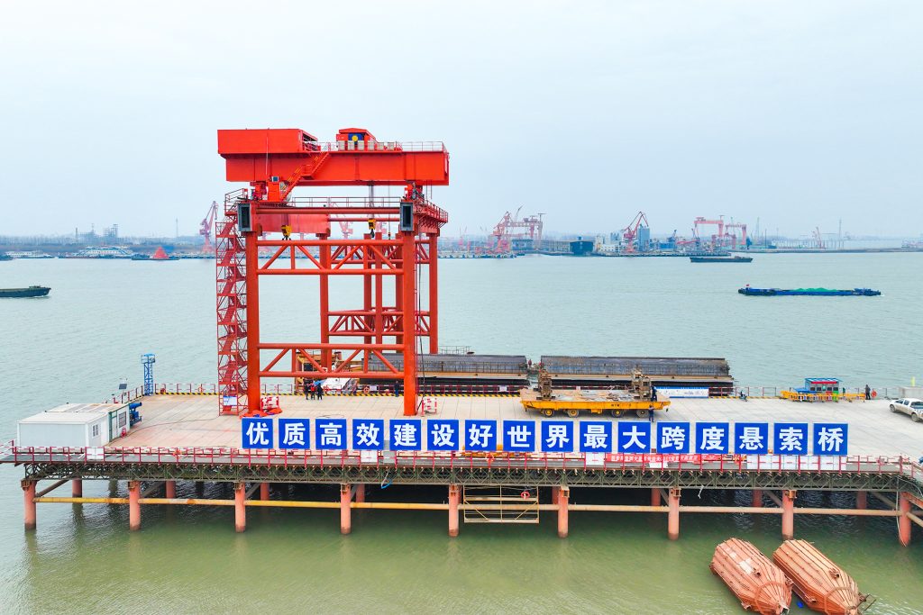
Bridge fabrication, metro construction and ship block assembly.
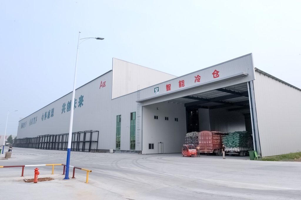
Automated storage and retrieval for plates, cables and bins.
Follow project dispatches, crane engineering and factory acceptance.
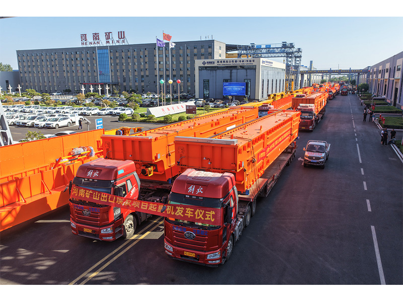
Dispatch, installation and equipment in service
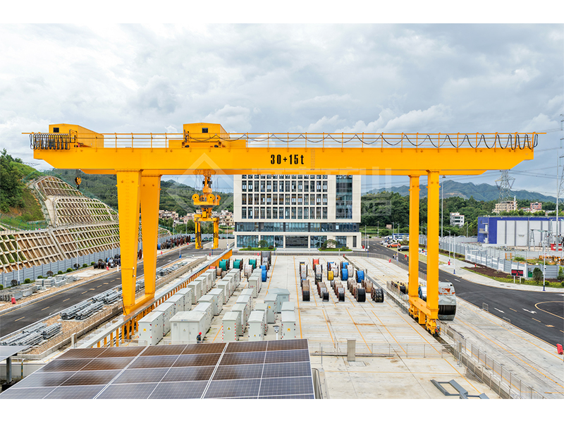
Crane configurations and handling technology
Factory inspections, acceptance and test programmes

Company developments, people and community programmes
Lift equipment from its operating position and move it along a connected overhead maintenance route. KSX combines an electric-hoist trolley, suspended bridge sections and a rail-transfer device. The 12.5 t reference arrangement for coal-mill maintenance links powered and manual bridge travel under a unified control system.
Share the equipment weight and the route from removal to the service position. A maintenance-area plan helps us choose the bridge sections and transfer arrangement.

Start with the heaviest maintenance item, pickup height and destination. A route sketch helps identify which sections need powered travel.
The hoist trolley passes between aligned handling sections through the specified transfer connection, serving pickup and maintenance positions within one planned route.
The 12.5 t arrangement combines an electrically travelled bridge with a manually travelled bridge. Select the travel method for the location, working frequency and maintenance procedure.
The trolley, bridges and transfer device form one coordinated package. Controls and the transfer sequence are defined around the connected rail layout.
Lift and move equipment for coal-mill servicing using the dedicated suspended route. Select pickup height and service position around the actual mill and removable components.
Connect lifting positions with maintenance or laydown locations. Include load dimensions, lifting fixtures and the required positioning when defining the route.
Use linked crane sections where equipment needs to pass between separated working positions. The transfer geometry is designed as part of the system rather than added to an unrelated crane.
The listed 12.5 t arrangement is A3 maintenance equipment for −25 to +40°C. State any classified-area or process-load requirement so an appropriate package can be considered.
Compare the available options for your lifting task. Capacity, span, lift height and speed are matched in the selected configuration.
| Model | KSX |
|---|---|
| Reference system rating | 12.5 t for the linked handling arrangement |
| System composition | Electric-hoist trolley, powered-travel suspended bridge, manual-travel suspended bridge and rail-transfer device |
| Crane working duty | A3 for the listed powered and manual bridge components |
| Hoist-trolley mechanism duty | M3 |
| Travel-mechanism duty | M3 for the listed components |
| Hoist-trolley span / lifting-height value | 1.3 m / 8 m |
| Powered bridge span / lifting-height value | 3.65 m / 3.50 m |
| Manual bridge span / lifting-height value | 3.70 m / 3.90 m |
| Hoist-trolley lifting / travel speed | 4.66 / 10 m/min |
| Powered bridge travel | 20 m/min |
| Manual bridge travel | Manual; no powered travel-speed rating |
| Hoist motor power | 13 kW for the listed hoist trolley |
| Travel motor power | Hoist trolley: 4 × 0.4 kW; powered bridge: 4 × 0.8 kW |
| Wheel diameter | 154 mm for the listed component arrangement |
| Controls | Unified electrical system and button control |
| Reference ambient temperature | −25 to +40°C |
| Reference humidity / process limits | Not selected for corrosive-gas areas or relative humidity above 85%; hazardous or molten loads require a different package |
| Power supply | Destination voltage/frequency specified with the electric hoist and powered travel equipment |
| Component in the 12.5 t set | Rated load | Span | Component lifting-height value | Duty | Lift / travel speed |
|---|---|---|---|---|---|
| Electric-hoist trolley | 12.5 t | 1.3 m | 8 m | M3 | 4.66 / 10 m/min |
| Powered-travel double-girder suspended bridge | 12.5 t | 3.65 m | 3.50 m | A3; travel M3 | Travel 20 m/min |
| Manual-travel double-girder suspended bridge | 12.5 t | 3.70 m | 3.90 m | A3; travel M3 | Manual bridge travel |
These are three components of one linked 12.5 t arrangement, not three separate loads to add together. Their lifting-height values are not additive; the complete route’s usable hook positions are confirmed on the arrangement drawing.
| Component | Hoist motor | Travel motors | Wheel diameter |
|---|---|---|---|
| Electric-hoist trolley | 13 kW | 4 × 0.4 kW | 154 mm |
| Powered-travel bridge | Lifting by the system hoist trolley | 4 × 0.8 kW | 154 mm |
| Manual-travel bridge | Lifting by the system hoist trolley | Manual bridge travel | 154 mm |
The manual-travel description applies to bridge movement. The shared hoist trolley retains its electric lifting system. Final wheel reactions and transfer-connection loads are supplied for the ordered layout.
Compare the hoist trolley, bridge sections and connection positions as one handling layout. The order identifies which sections are powered, which are manually travelled and where transfer is permitted.

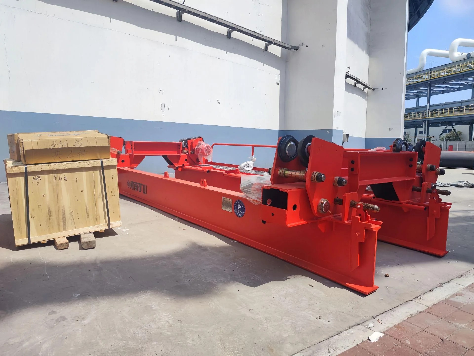
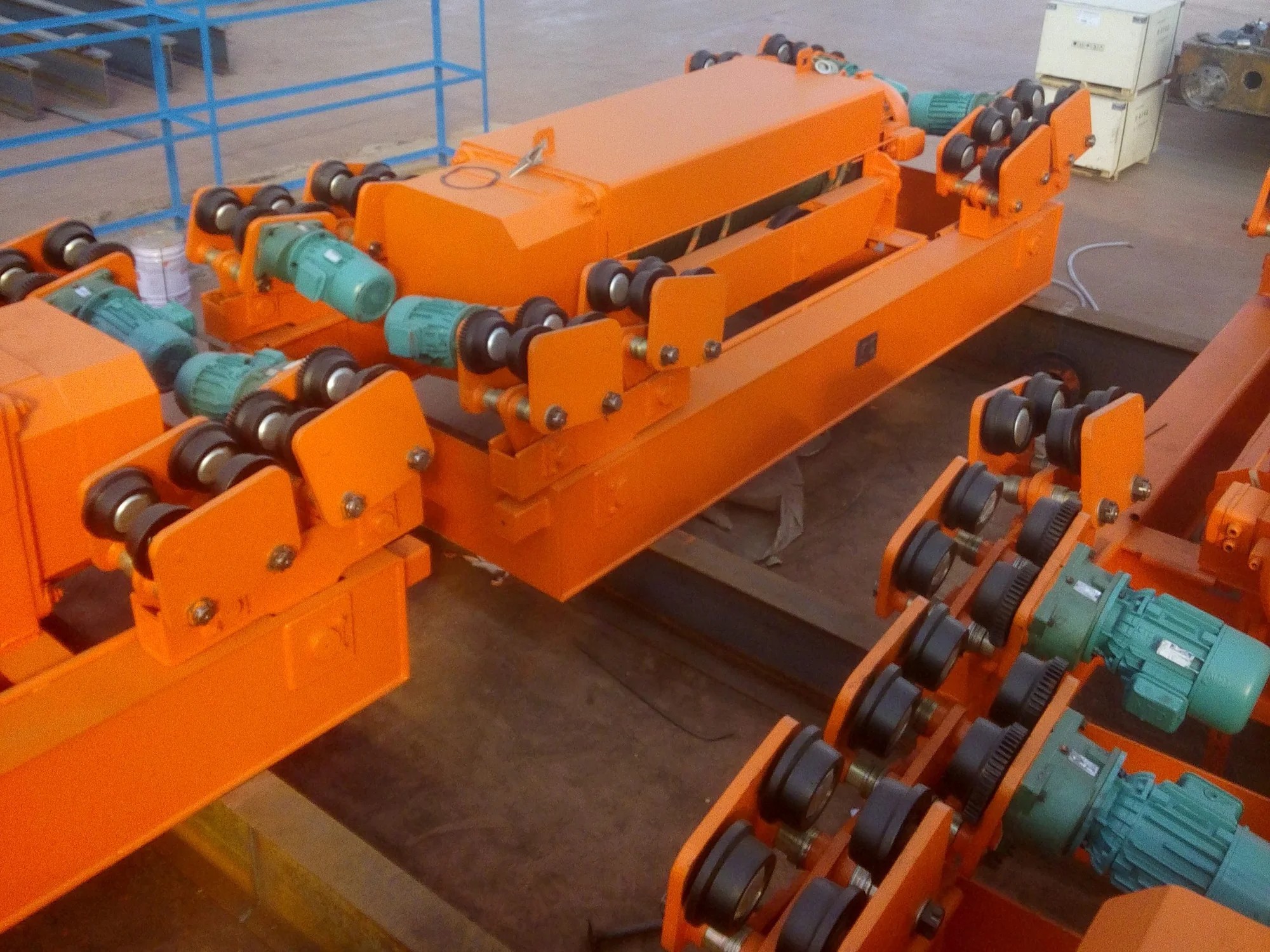
Follow the equipment from pickup to the service area and back. The proposal matches the trolley, bridge sections and transfer connection to the load and route.
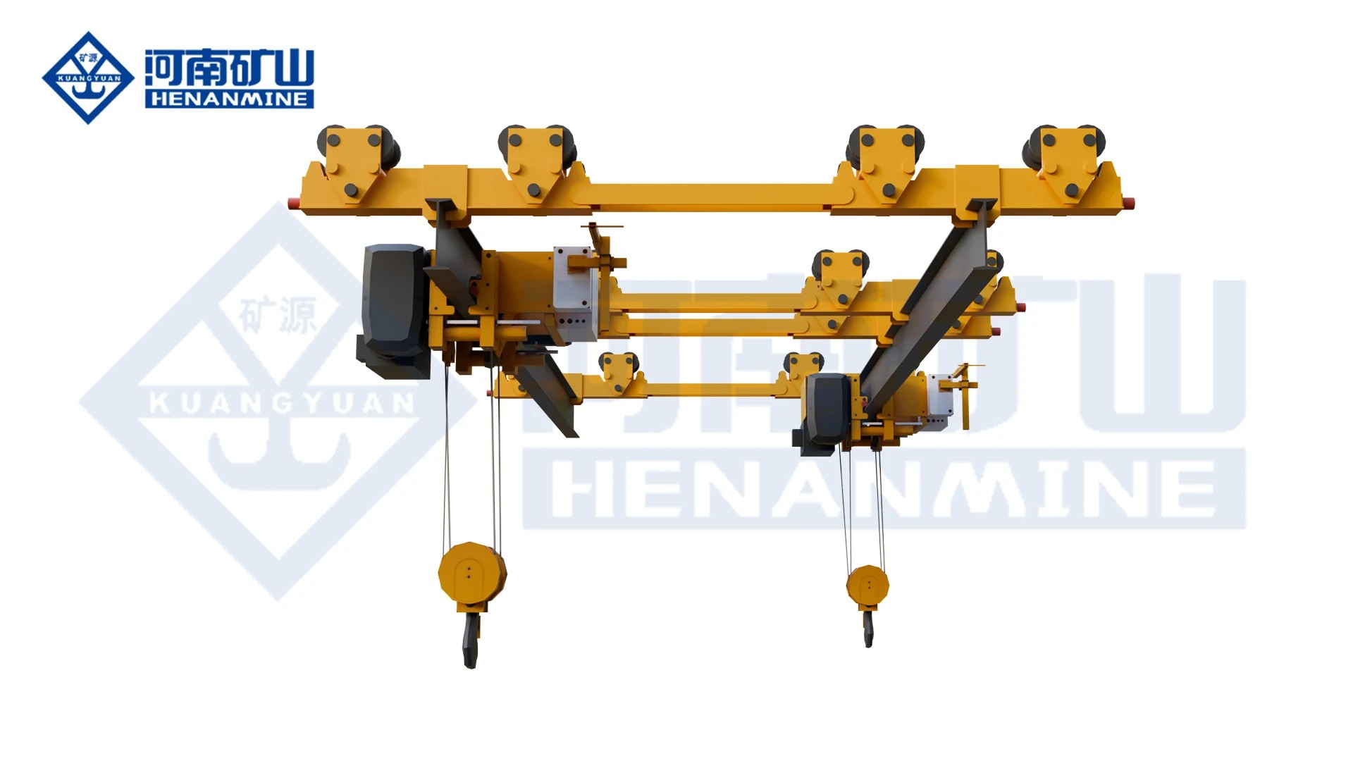
List the equipment, fixture and largest suspended dimensions. Mark removal, transfer, laydown and reinstallation positions on the maintenance-area plan.
Select the travel arrangement for each section. The illustrated set has both types; manual bridge travel does not mean that the electric hoist is unpowered.
Agree alignment, connection/locking checks, trolley transfer and the permitted movement of the connected sections. Include the control indications and recovery procedure.
Keep the 12.5 t component data together. State required hook travel and operating hours, and identify any temperature, humidity or process exposure outside the listed conditions.
Compare a complete maintenance route, including the transfer connections and controls.
Enquire for one KSX system or several service routes. The offer identifies the electric-hoist trolley, powered and manual bridge sections, and transfer devices included for each route.
Request an itemised offer for the trolley, each bridge section, rail-transfer devices and unified controls. Fixed or connecting rails, power feeds, supports, freight and installation services are listed explicitly.
Agree the route drawing, component ratings and dimensions, transfer and locking sequence, support reactions, wiring information and manuals. Include the inspection and loaded-transfer test records required for handover.
The quotation confirms engineering, production and dispatch dates for the selected route. Plan the arrival of bridge sections, transfer devices and connecting rails around the installation and maintenance shutdown window.
Define rail alignment, transfer-device installation and electrical connections in the site scope. Commissioning includes the agreed connection checks, loaded trolley transfers, permitted bridge movements and maintenance-team handover.
Confirm warranty duration, start date and coverage for the hoist, travel assemblies, transfer devices and controls. Agree service contacts and recommended connection, drive and control spares for maintenance planning.
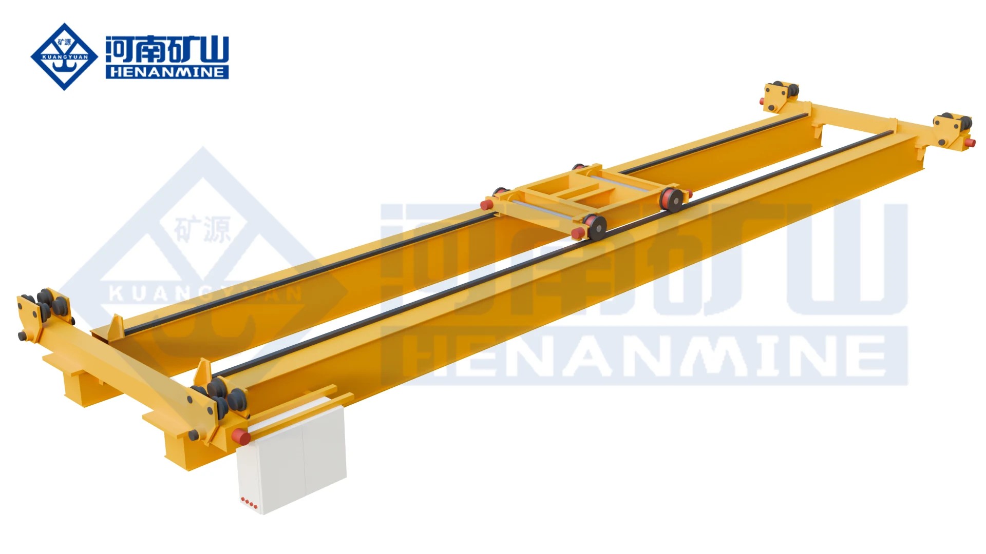
Cover a defined production area with a double-girder underhung crane matched to the load and duty.
Compare this arrangement ↗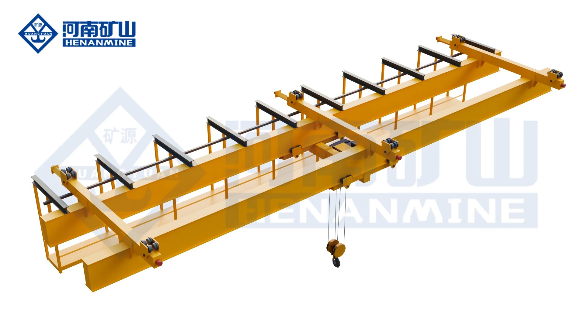
Cover wide workshop areas with a multi-point suspended double-girder electric-hoist bridge.
Compare this arrangement ↗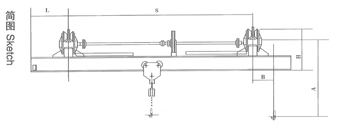
Handle occasional lifts and short transfers with a hand-operated suspension crane.
Compare this arrangement ↗Find the arrangement, equipment options and order information that suit your application.
The system provides a route for the hoist trolley to pass between compatible, aligned handling sections. The arrangement drawing defines the connected rails and transfer operation; it is not a whole bridge changing from one unrelated runway to another.
No. The listed components form one linked 12.5 t handling arrangement. The permitted suspended load stays within the system and individual component ratings throughout the route.
They describe different components: 1.3 m for the hoist trolley, 3.65 m for the powered bridge and 3.70 m for the manual bridge. They are not alternative widths of one interchangeable crane.
No. Manual refers to the bridge’s travel arrangement. The system uses an electric-hoist trolley, listed with 4.66 m/min lifting and 10 m/min trolley travel.
The illustrated hoist trolley lists 8 m lift, with separate component lifting-height values for the bridge sections. Usable hook positions along the complete route are confirmed on the arrangement drawing; the three values are not added together.
Transfer follows the specified alignment and connection/locking sequence. Permitted trolley transfer and bridge movements are defined with the connection and controls, then checked during commissioning.
No. The listed KSX arrangement is not an explosion-proof package. State any classified-area requirement separately when planning the maintenance installation.
The listed maintenance configuration is not selected for molten metal, toxic, flammable or explosive loads. Those duties require an appropriately designed and specified lifting package.
A system can be reviewed for a similar maintenance or transfer requirement. Send the route, maximum load, lifting levels and control needs so a definite component and connection arrangement can be quoted.
Send the equipment weight/dimensions, pickup and service positions, rail layout and desired powered/manual sections. Include hook travel, working frequency, site power and installation responsibilities.
Yes. Single-system enquiries are welcome. Tell us the lifting task and site location; the quotation confirms the ordered quantity and the complete crane, runway-interface and service scope.
The written quotation confirms production and dispatch dates for the selected configuration, together with warranty duration, start date, coverage and the after-sales contact. Packing, freight and site commissioning are identified separately so you can plan the complete delivery.
Tell us the equipment weight, pickup and service positions, required lift and project location. Add a route sketch and your preferred powered or manual travel sections if known. We will help develop a matched handling system and quotation.
info@cranehenanmine.com