What distinguishes MDE from MDG?
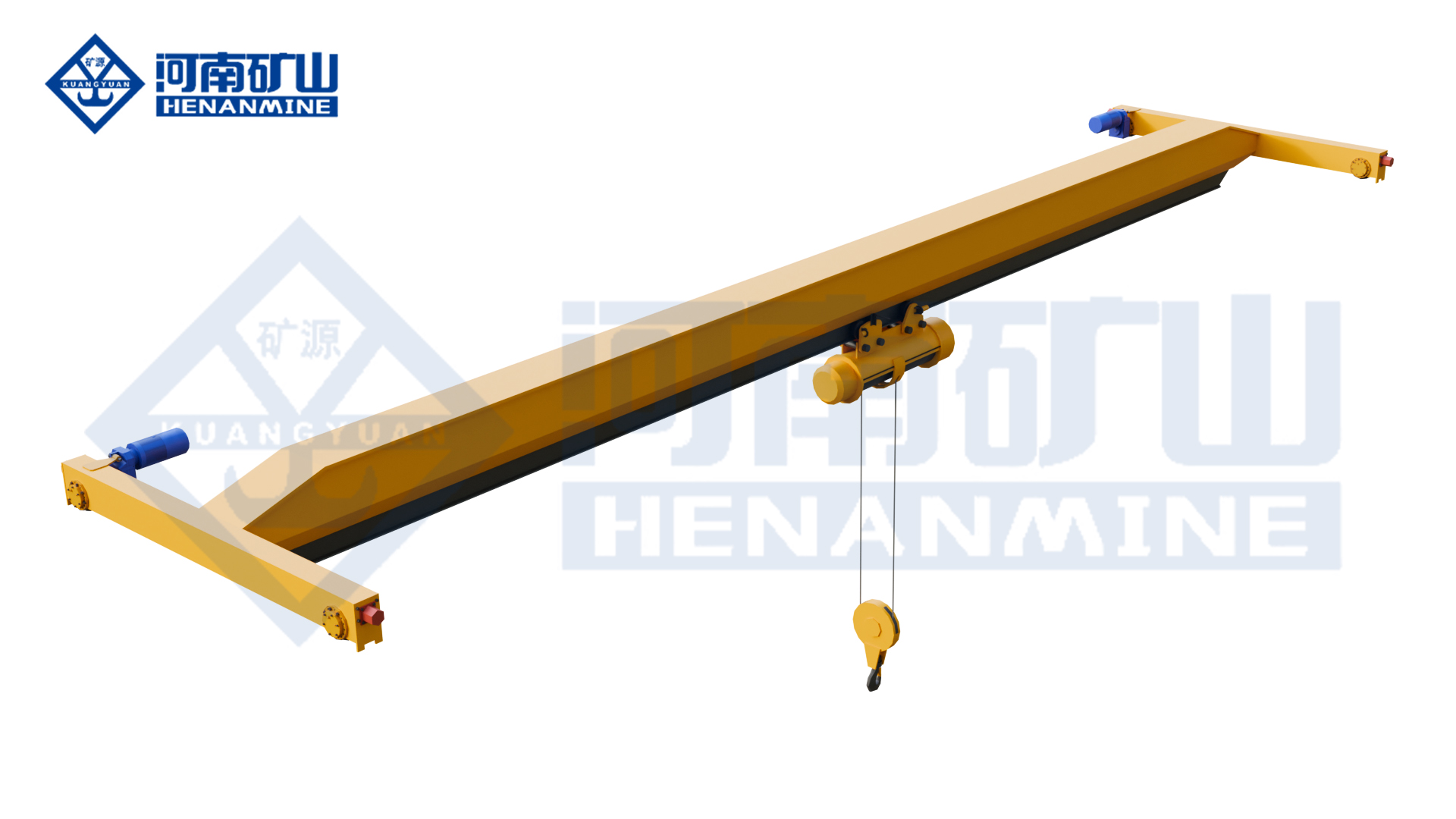
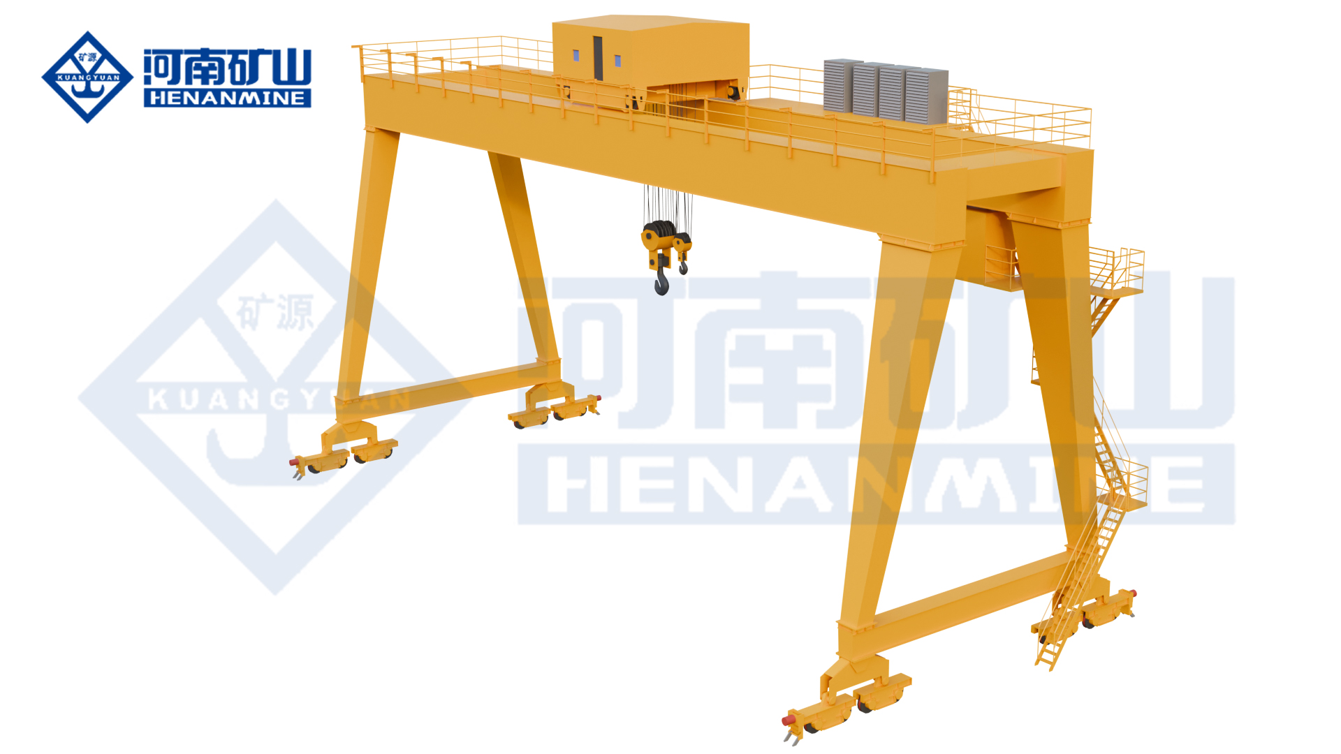
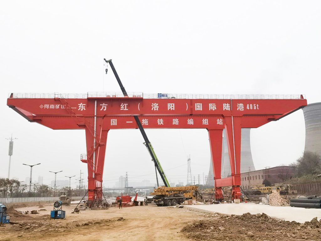
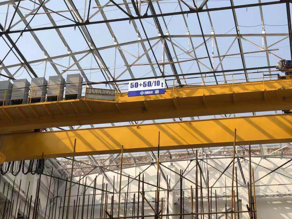
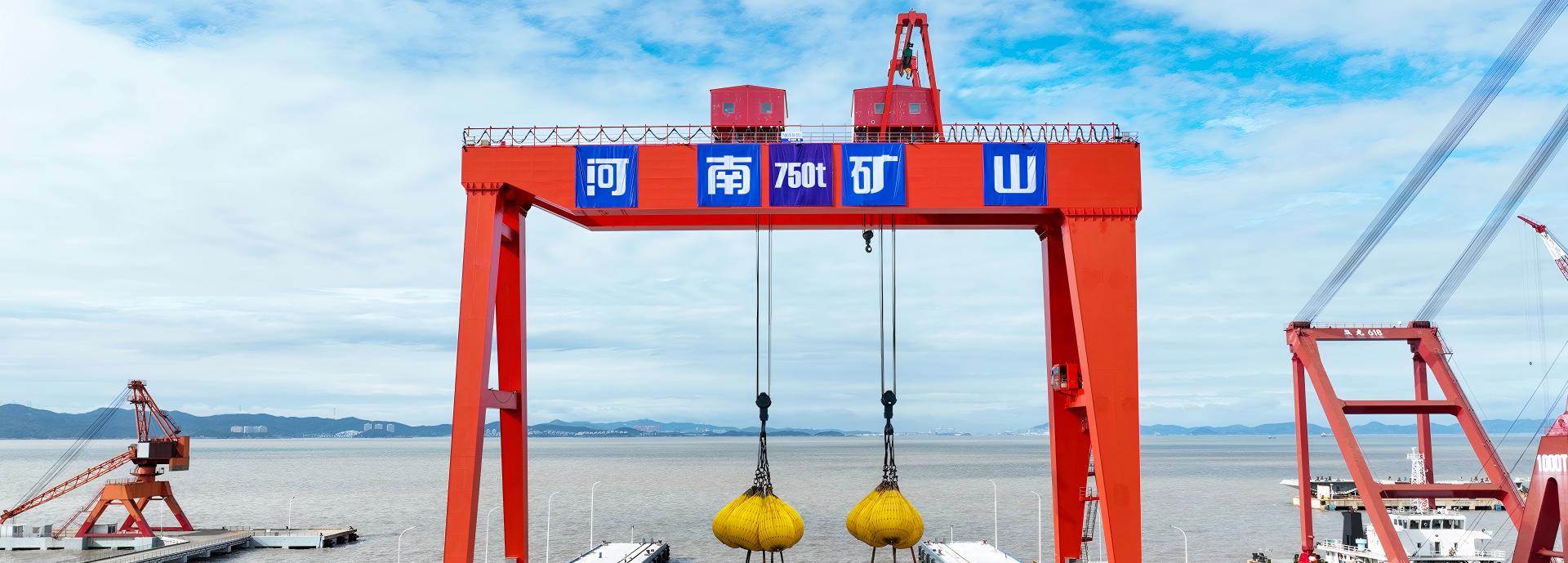
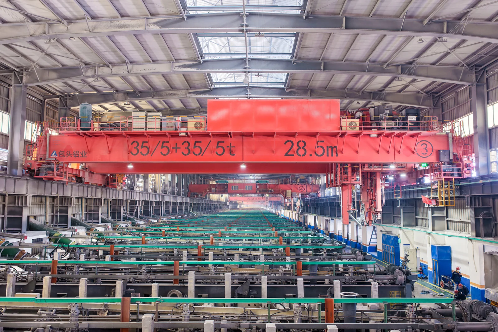
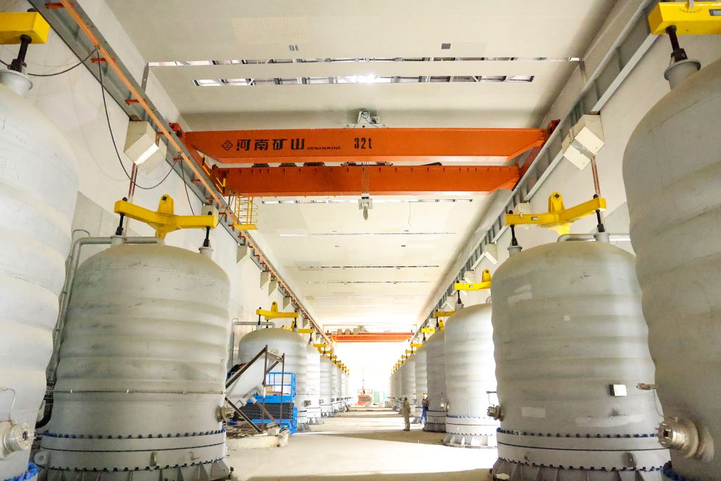
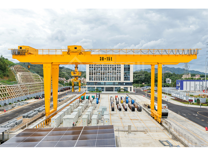
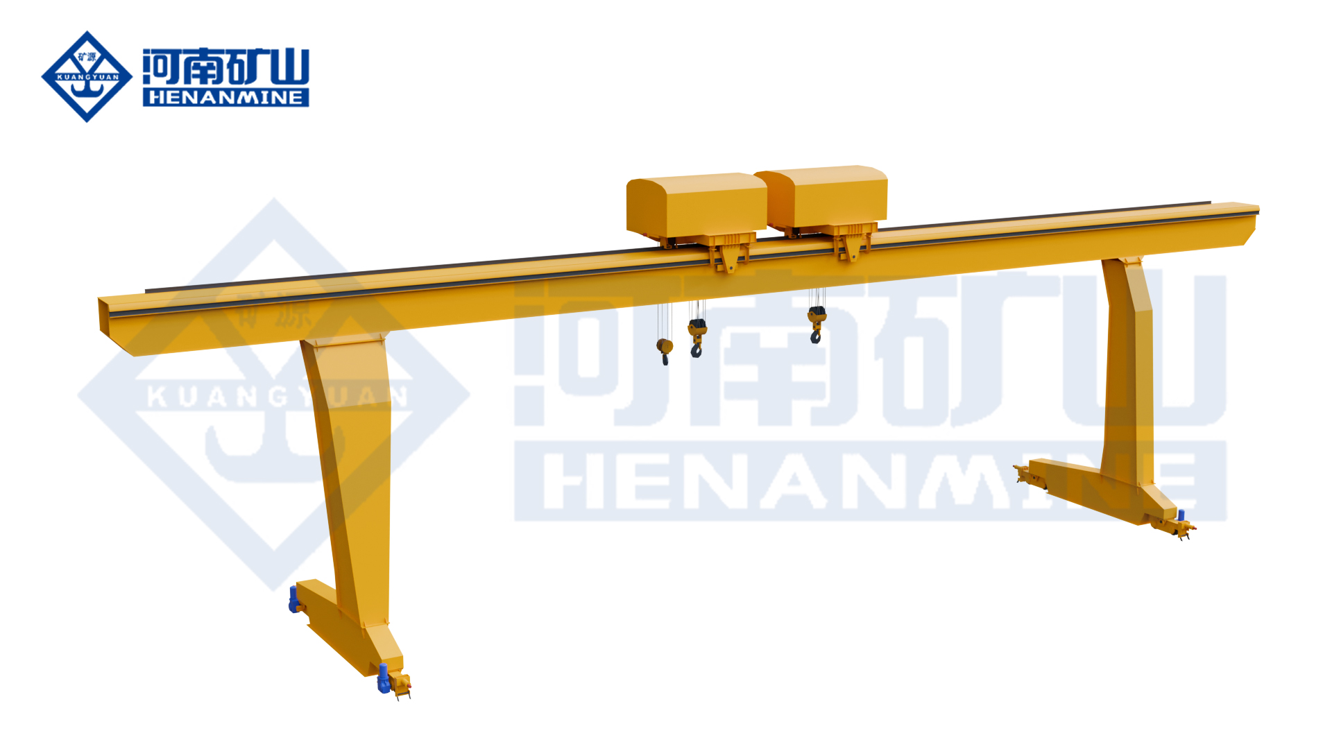
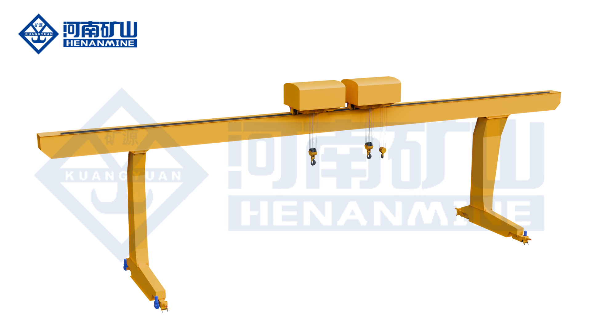
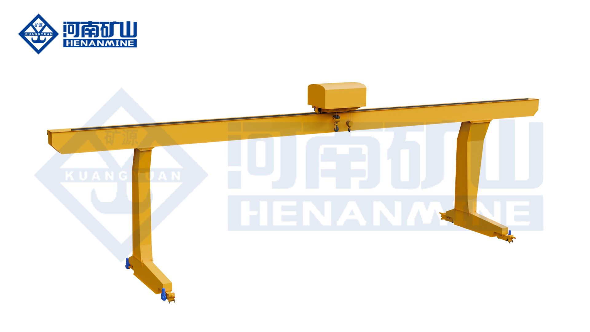
MDE is the double-trolley development of the MDG L-type single-girder arrangement. It has two winch-lifting trolleys, while the MDG arrangement here has one. The additional lifting position brings trolley spacing, load distribution and operating modes into the selection.
Can I add the two trolley ratings to calculate capacity?
No. Each trolley has a selected rating, and the permitted load carried together is specified for the complete arrangement. Load distribution, lifting-point spacing and operating mode must match that condition throughout the intended move. The equipment and control schedules should identify those limits alongside each individual rating.
Does the 5–50 t range describe each trolley?
It describes the MDE model selection range. It is not a per-trolley rating or a shared-load schedule. The selected offer identifies each trolley rating and any permitted shared-load condition, together with the chosen span and mechanisms.
What lifting-point information is useful?
Provide the component dimensions, lifting-point positions and known load at each point, including the lifting accessories. Identify pickup and landing positions and any change in separation needed during the sequence. A simple sketch is useful while the detailed arrangement is being developed.
Are independent and joint trolley movements included as standard?
Describe the movements your handling sequence needs and agree them in the selected control package. The offer should identify the permitted independent or coordinated functions, the applicable loads and the operator's authority in each mode, so the equipment matches the actual task.
Can a long component turn through the L-shaped legs?
A planned turn must be checked against the selected opening and both hook positions. Include the component, lifting connections, rigging and nearby vehicles or stacks through the entire sequence. Define the turning method and any separate equipment needed, then agree the permitted crane movements. Two trolleys provide lifting positions; they do not by themselves specify automatic load rotation.
How are the runways and foundations selected?
Use the selected geometry, wheel arrangement and reactions for the two ground-level runways and foundations. Relevant lifting positions and permitted two-trolley load conditions belong in that interface. Coordinate rail centres, travel length, loading and parking positions, wind conditions, traffic and the incoming power-feed route with the site and installation scope.
Can I request a proposal before all load-sharing details are available?
Yes. Start with the overall load, approximate span, useful lifting height and destination, leaving unknown items open. Describe the component or provide an optional sketch. The proposal can then develop lifting-point spacing, individual and shared loads and the operating functions needed before the equipment arrangement is finalised.
Is rail-centre span the space available for my component?
Span is the horizontal distance between runway rail centre lines. Usable passage also depends on the L-leg geometry, mechanism envelopes, hook approaches and the component's height and orientation. Compare the full workpiece and both lifting connections with the dimensioned opening and useful hook coverage.
What should the two-trolley supply and acceptance scope include?
Identify both winch packages, hook equipment, travel drives, selected control functions and power-feed equipment, with individual ratings and shared-load conditions stated clearly. Agree the required documents, factory tests and site checks for those ordered functions. The offer should also allocate rails, foundations, site connections, assembly and commissioning, with warranty and support terms for the included equipment and services.