
Trolley ratings and attachments
Specify each lifting point, hook, attachment and complete load. Agree shared-load limits separately from individual ratings; include any grab or electromagnet power and control connections as an explicit package.
Bridge cranes for workshops and production lines.
Explore Overhead Cranes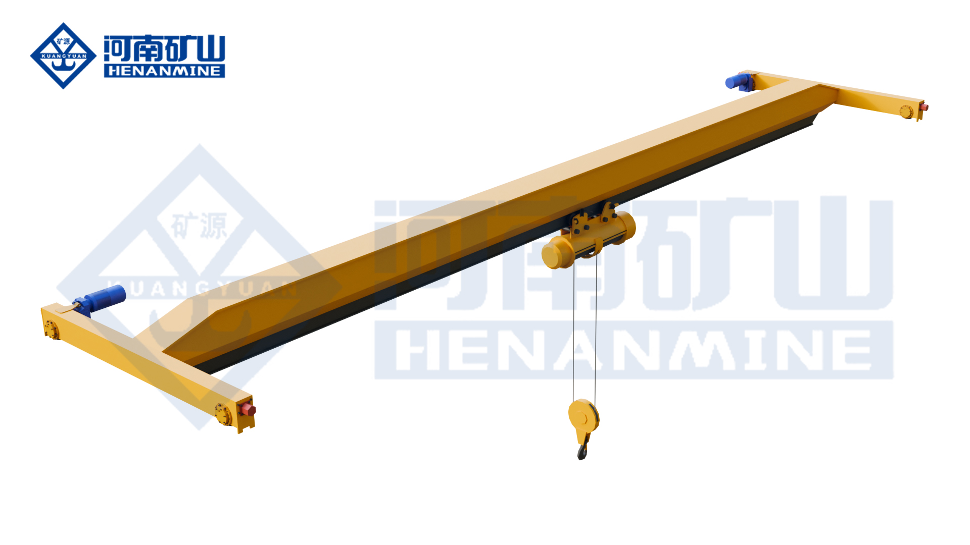
Ground-supported lifting for yards and construction.
Explore Gantry Cranes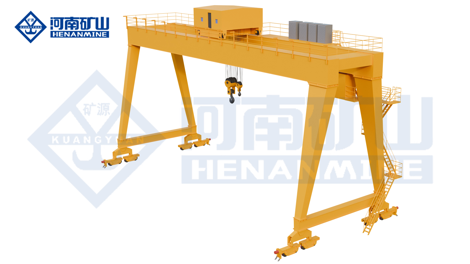
Wire rope and chain hoists for lifting points and cranes.
Explore Electric Hoists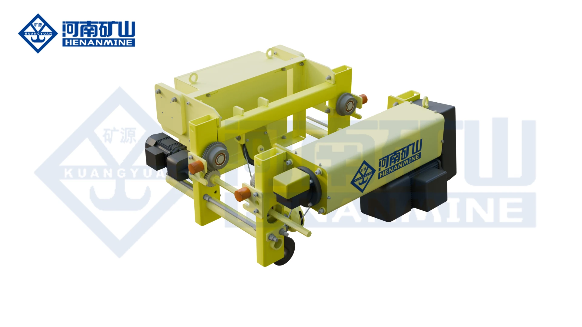
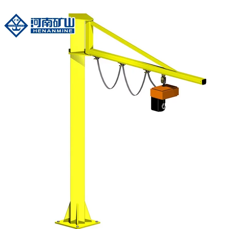
Wire rope lifting and pulling with a powered drum.
Explore Electric Winches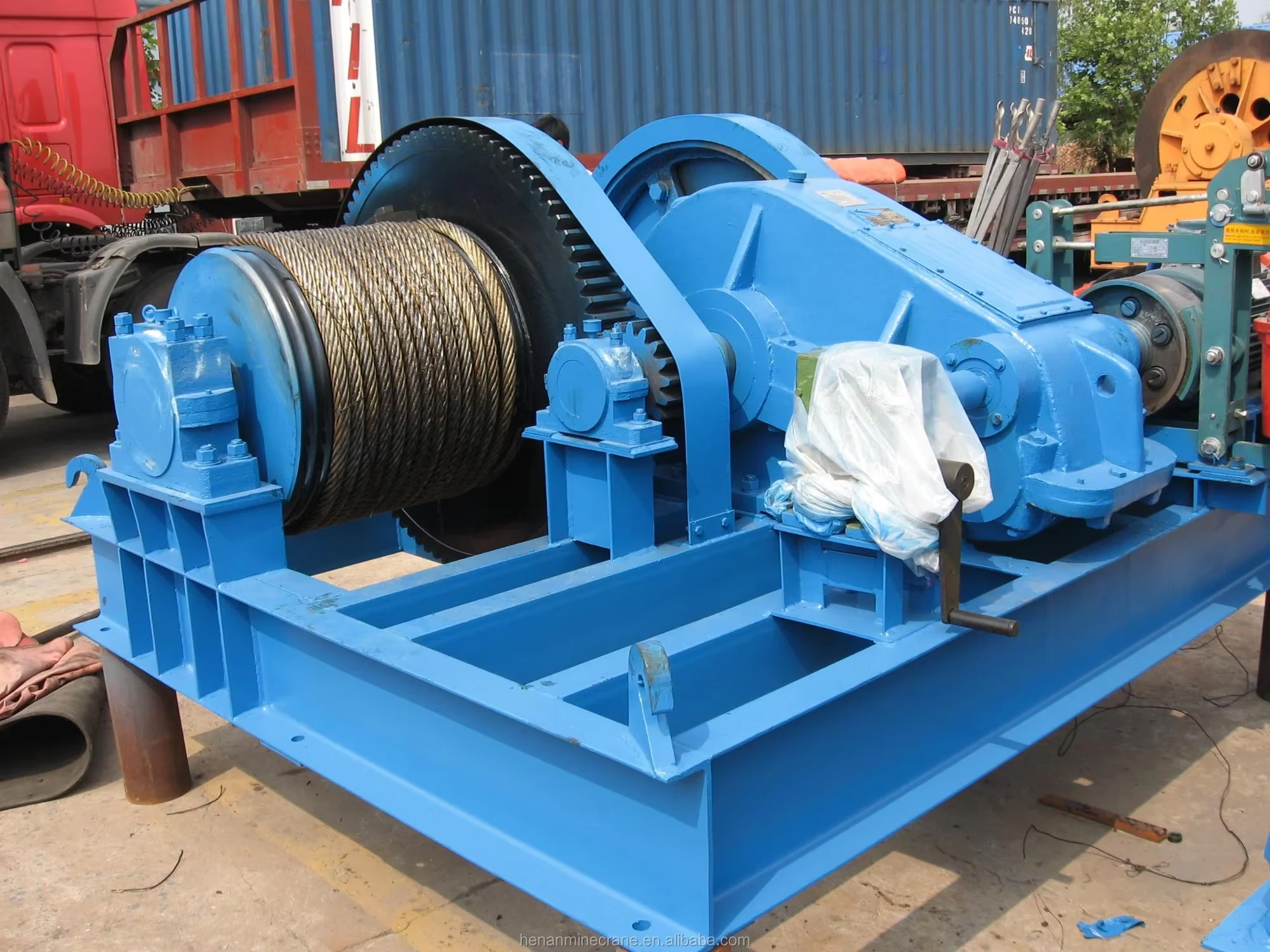
Grab buckets, magnets and hooks for your load.
Explore Lifting Attachments & Grabs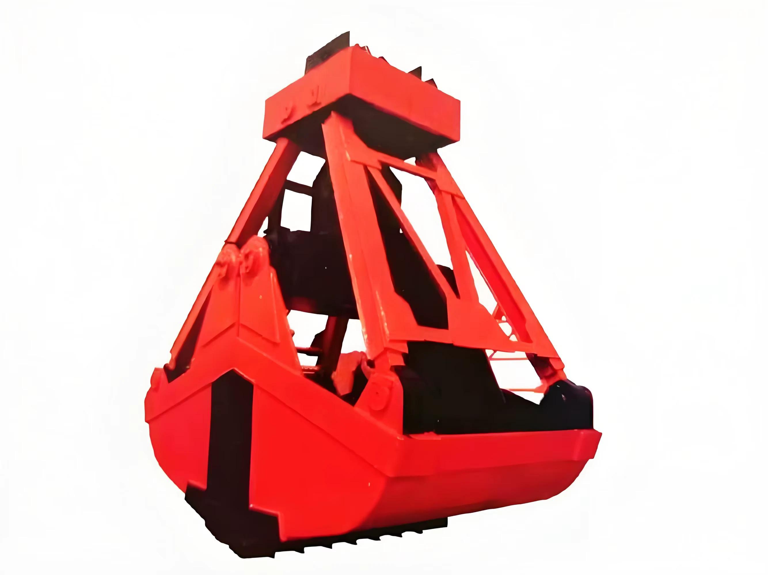
Mobile handling for containers, precast and yard loads.
Explore Rubber-Tired Gantry Cranes & Straddle Carriers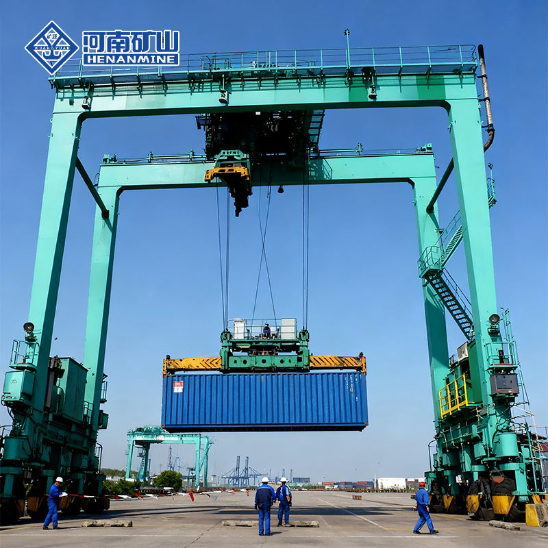
Lift and move vessels through boatyards and marinas.
Explore Marine Travel Lifts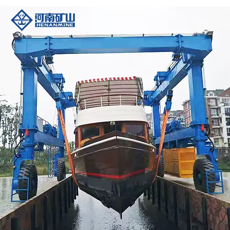
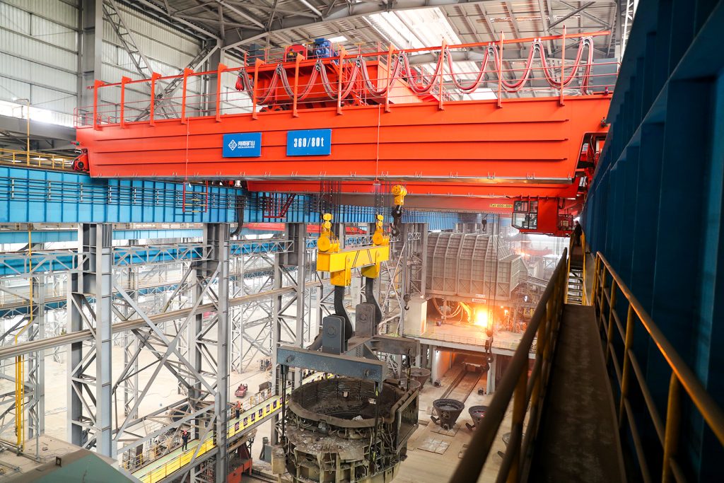
Ladle, slab, scrap and coil handling across steel production.
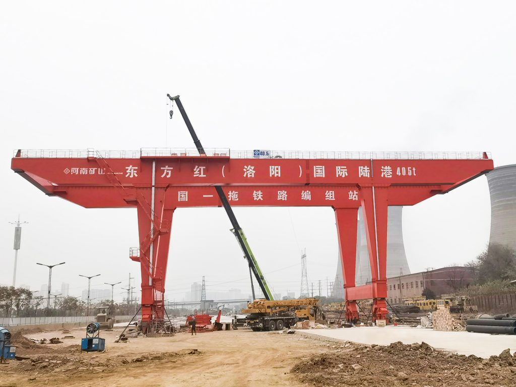
Container stacking and cargo transfers across terminals and rail.
Turbine installation, powerhouse maintenance and wind equipment assembly.
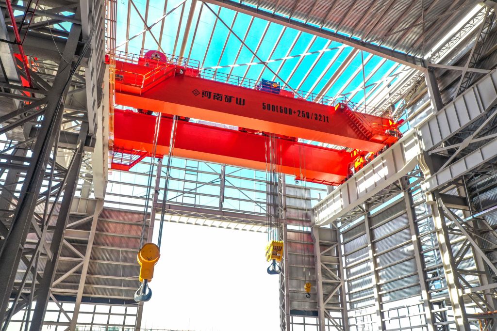
Controlled component transfer and positioning for precision assembly.
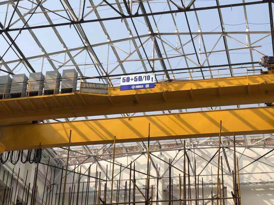
Heavy fabrication, production lifting and factory crane automation.
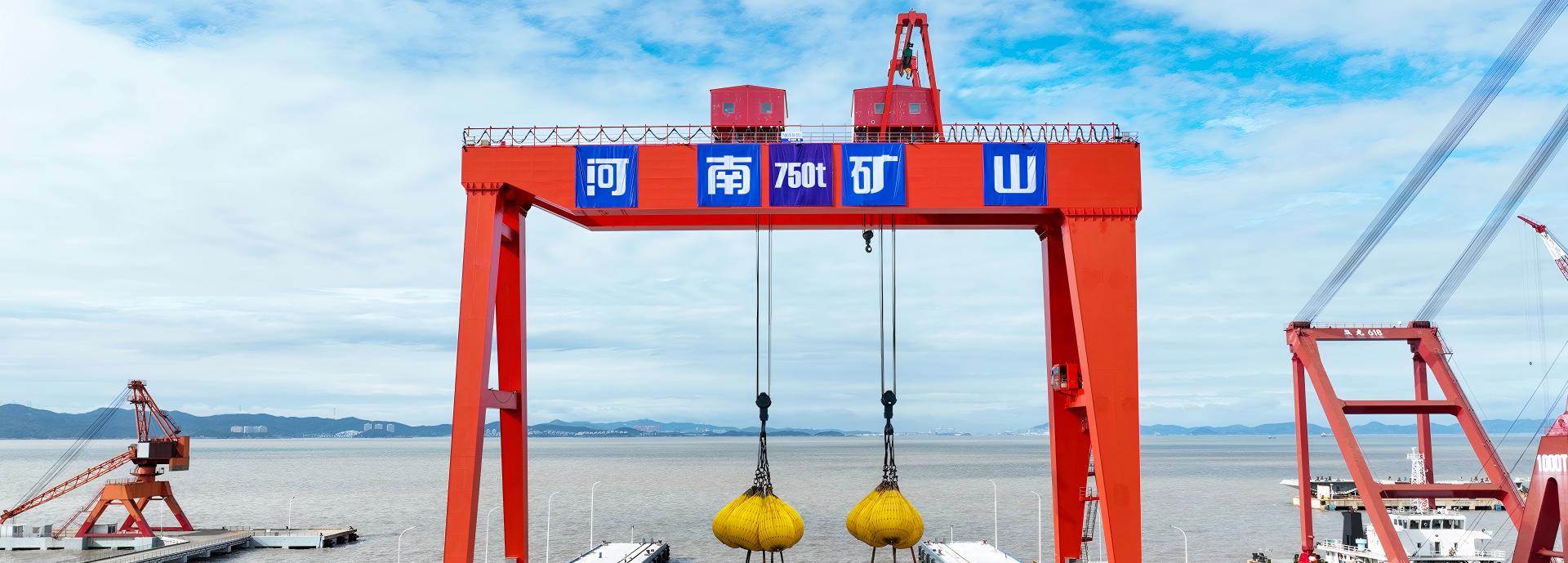
Process lifting for smelters, carbon blocks and anode materials.
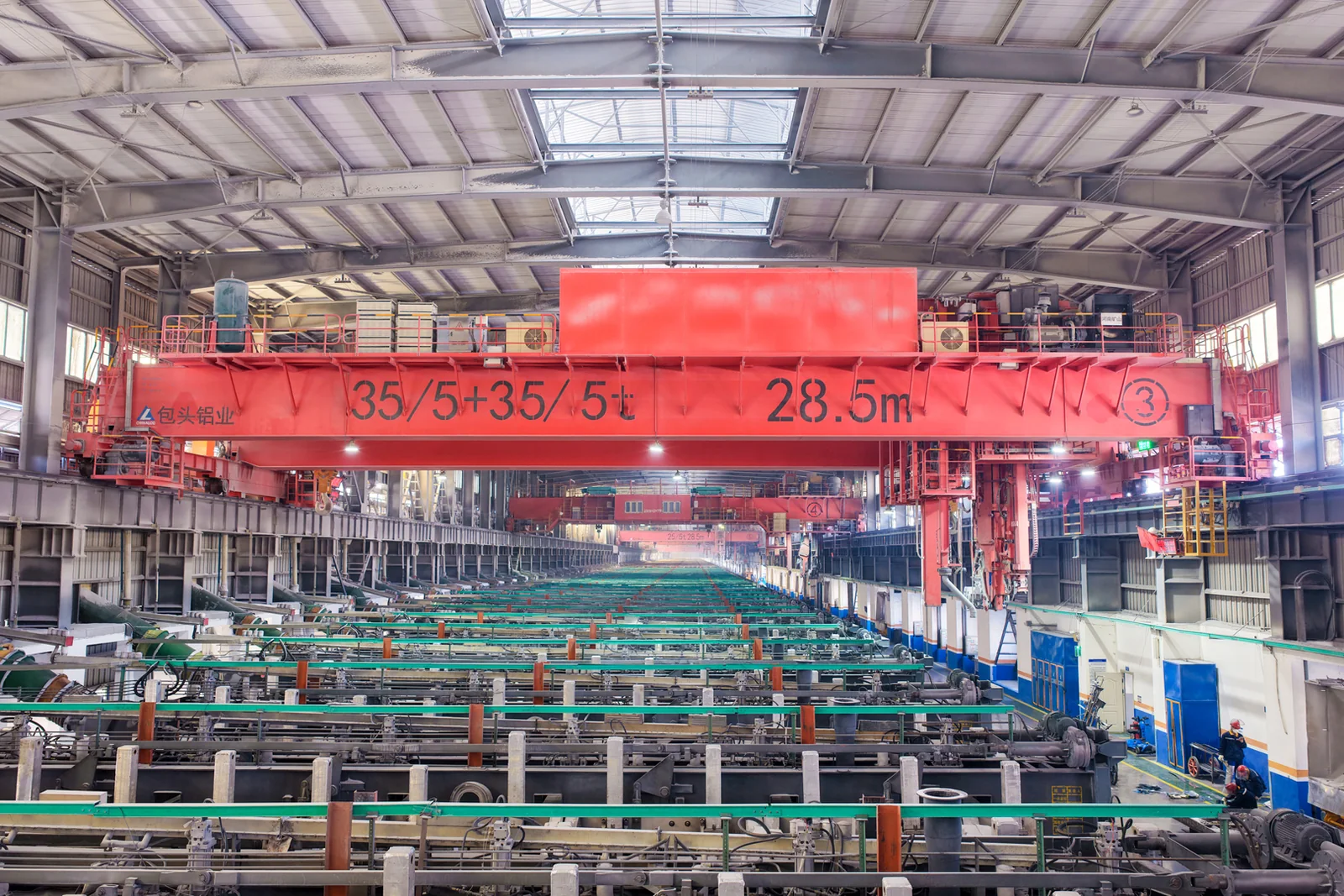
Clean lifting and classified protection for sensitive process areas.
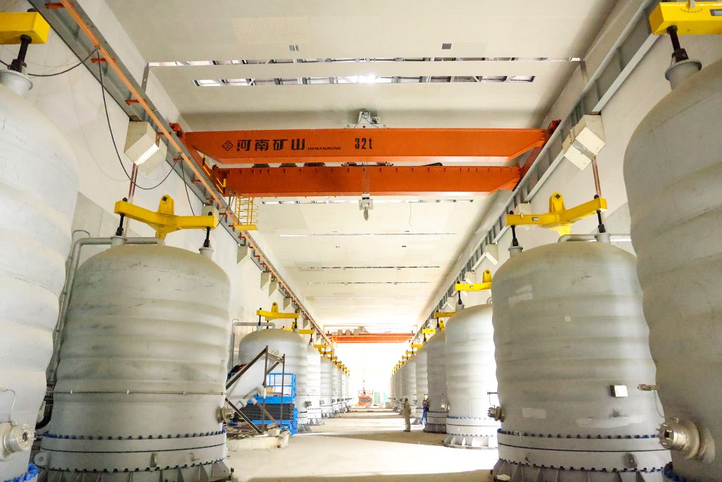
Bridge fabrication, metro construction and ship block assembly.
Automated storage and retrieval for plates, cables and bins.
Follow project dispatches, crane engineering and factory acceptance.
Dispatch, installation and equipment in service
Crane configurations and handling technology
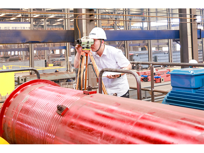
Factory inspections, acceptance and test programmes

Company developments, people and community programmes
MGBE combines two lifting trolleys with a semi-gantry layout beside an elevated runway. Select variable-frequency motion and communication functions for the actual process. Agree trolley loads, spacing and permitted modes, then coordinate both support levels and any linked-crane interfaces within the defined equipment scope.
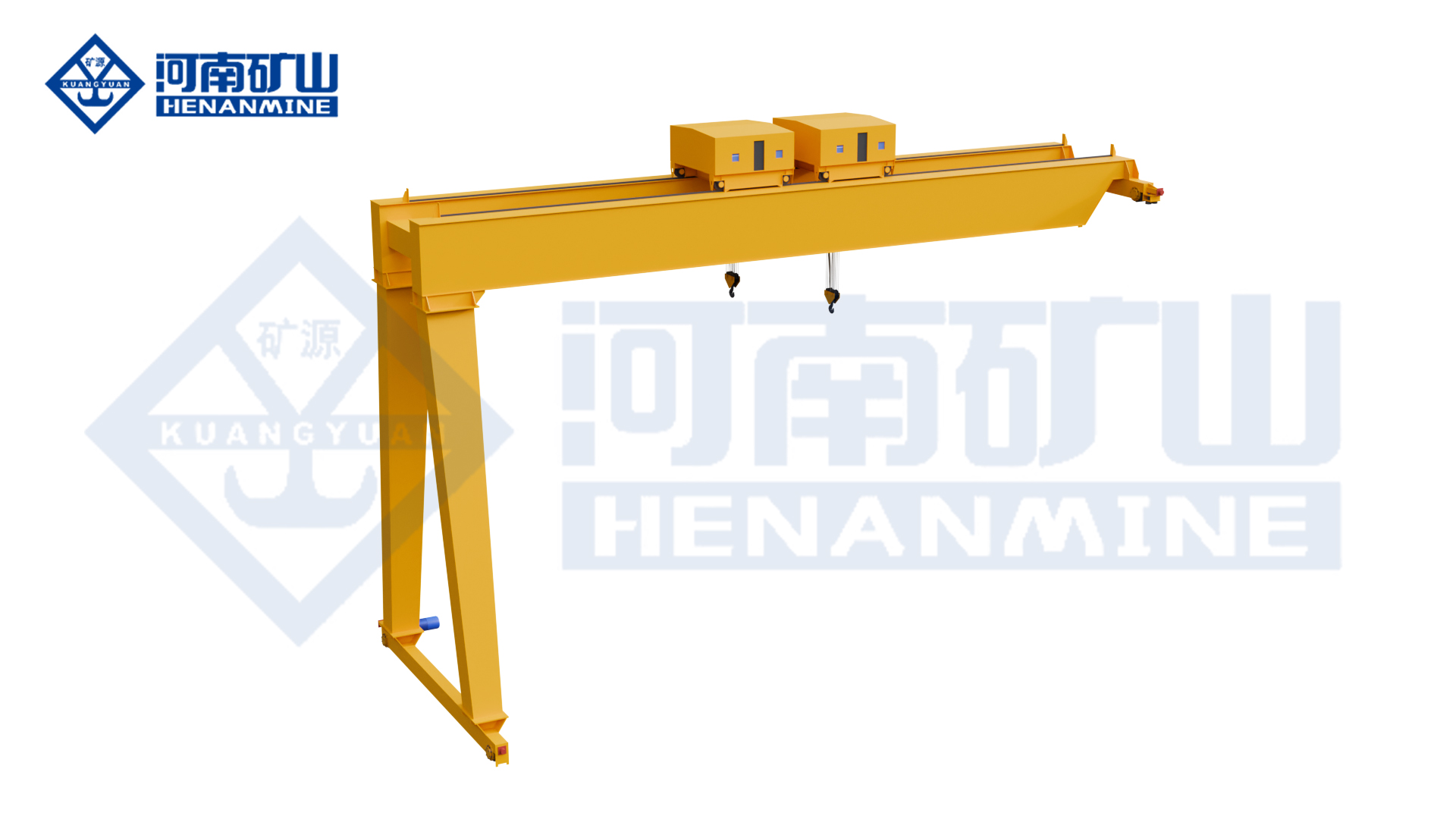
Two lifting positions may suit a long component moving through a wall-side assembly area. The proposed trolley separation and shared-load conditions need to follow the component's actual lifting points.
A specified communication package can connect cranes working within an agreed area. Define the required sequence and control authority so each crane's role is clear within the shared process.
Hook, grab or electromagnetic arrangements are selected for the material and process. Each lifting mode brings its own attachment mass, power requirements and operating conditions into the semi-gantry proposal.
Compare the lifting mechanism, control functions and site interfaces for the selected crane.
Trolley ratings, permitted shared loads and control functions are selected for the project. A3–A8 is a family range; communication choices define the integration scope.
| Model | MGBE | Crane arrangement | Double-trolley semi-gantry |
|---|---|---|---|
| Trolley arrangement | Two lifting trolleys | Working-class range | A3–A8; select the class for the operating cycle |
| Drive control | Variable-frequency motion control | Communication choices | 5G or industrial Ethernet communication for crane information synchronisation |
| Coordinated system | Multi-crane linked operation within a specified shared working area | Available attachments | Hook, grab or electromagnetic arrangements selected for the process |
| Rated lifting capacity | Specify trolley ratings and the permitted shared lifting load | Span | Rail-centre span selected for the floor-side and elevated-side runways |
| Lifting height | Working hook levels selected with both runway elevations | Lifting-point spacing | Trolley separation selected for the load geometry |
| Permitted operating modes | Trolley and multi-crane independent / joint functions specified in the control scope | Communication integration | Network coverage, interfaces and system responsibilities agreed for the site |
| Elevated-runway support | Building-side or independent support reactions supplied for the selected layout | Floor-side runway | Rail interface, wheel loads and clear travel route coordinated |
| Motion speeds | Lifting and travel speeds selected for the coordinated process | Operator controls | Operator positions, visibility and control authority agreed for linked operation |
| Electrical supply | Crane and attachment supply and power-feed routes specified | Cantilever coverage | Any required outside-span coverage confirmed in the selected arrangement |
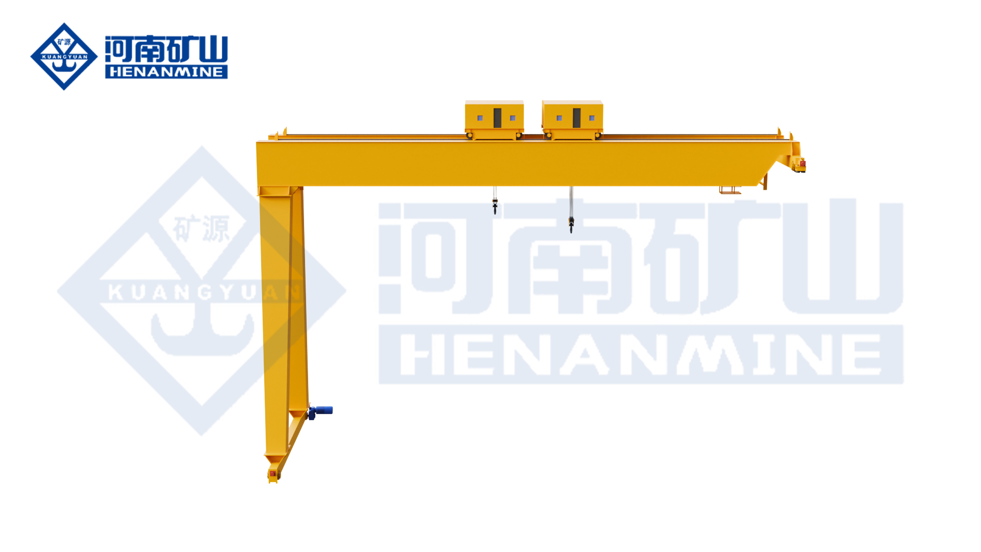
Review the original equipment views alongside the selected crane drawing.

Specify each lifting point, hook, attachment and complete load. Agree shared-load limits separately from individual ratings; include any grab or electromagnet power and control connections as an explicit package.
Check useful trolley separation, approaches and lifting-point positions. Show floor rail, elevated rail and working hook levels; use selected vertical and horizontal reactions for the building-side support and ground foundation. Keep floor crossings and the travelling-leg corridor clear.
Variable-frequency motion and selected 5G or industrial Ethernet can support information synchronisation. Distinguish two-trolley coordination from multi-crane integration; agree independent/joint movements, permitted sequence, operator authority, network coverage and responsibility for integration.
Choose observation positions for both lifting points and any cooperating crane. Coordinate the two runway routes, supply and power feed, electrical interfaces and access for inspection and service with the complete bay layout.
Enquire for one crane or your project quantity. Share load, rail-centre span, useful lift and destination; develop unknown dimensions, runway levels and support information with the proposal.
Distinguish trolley equipment, attachments, controls, communication devices and integration services. Confirm quantity, price and manufacturing schedule for the defined package.
Agree project requirements, arrangement, lifting/electrical schedules, reactions and operating documents. Include communication interfaces and operating-mode descriptions where supplied.
Define factory tests, site checks and acceptance records for individual lifting and agreed joint functions. Review control responsibilities; an unspecified network does not establish a verified handling system.
Coordinate transport, unloading and installation with floor-rail and elevated-runway readiness. Allocate site-network work, assembly, power connection and commissioning before delivery.
Provide maintenance instructions, spares and control-equipment support. Define warranty and after-sales responsibilities across crane and integration boundaries, including the correct contact for each system part.

Hook handling beside a suitable elevated runway in workshops and restricted bays
Electric-hoist handling beside a suitable elevated runway
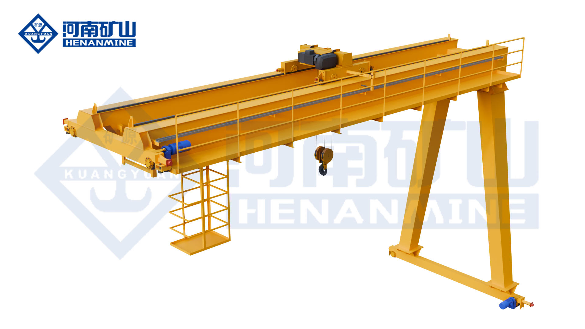
Top-running electric-hoist handling in a semi-gantry working bay
Compare the handling task, selected lifting equipment and supply scope before ordering.
It is a double-trolley semi-gantry. The layout uses a ground-running side and an opposite elevated runway, so both support levels and their reactions must be coordinated with the site.
The operating modes are selected for the task. State whether the trolleys work independently or support a shared load, and agree the permissible ratings and coordination functions for that operation.
They are different parts of the control scope. A project may need functions within one crane, information exchange between cranes, or both; the written description should identify what is supplied.
5G or industrial Ethernet communication can be selected for the required coordination functions. Choose the appropriate interface for the site; a new network is not necessary for every application.
Attachment arrangements are selected for the handling process. Confirm the attachment, its mass, power interface and mode-specific limits instead of treating every lifting device as included in a hook package.
A shared-load rating is not established by adding individual trolley capacities. The structure, load distribution and selected operating mode determine the permissible combined lifting condition in the proposal.
Provide the elevated runway position, floor-rail route, rail levels and available support information. The selected crane reactions allow the support designer to review the building-side and floor-side interfaces.
It should identify the crane equipment, permitted operating modes, communication hardware, integration work and acceptance scope. Installation, training, spares, warranty and support responsibilities should follow those same boundaries.
Tell us what you lift, the approximate span, the required lifting height and your destination. If a dimension is unknown, describe the task and leave that field open.