Steelmaking ladle transfer
Carry filled or empty ladles between defined production positions. Check the carrier-to-ladle fit, route clearance and station lifting levels alongside the gross suspended load.
Bridge cranes for workshops and production lines.
Explore Overhead Cranes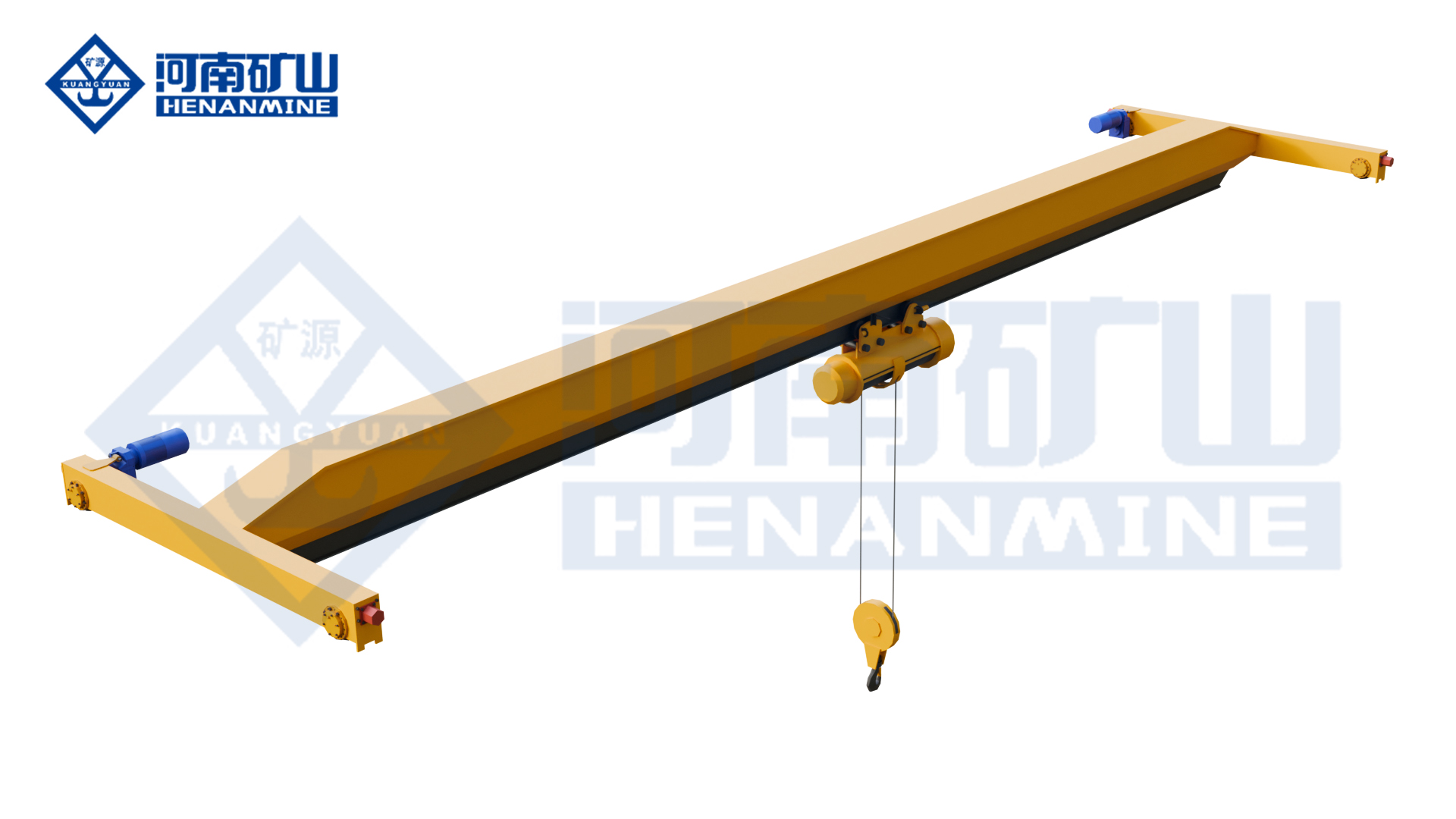
Ground-supported lifting for yards and construction.
Explore Gantry Cranes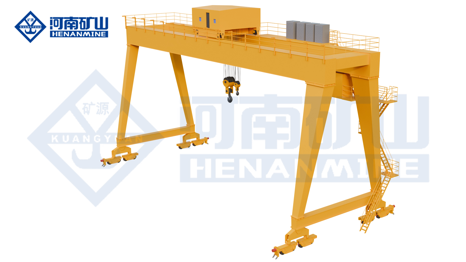
Wire rope and chain hoists for lifting points and cranes.
Explore Electric Hoists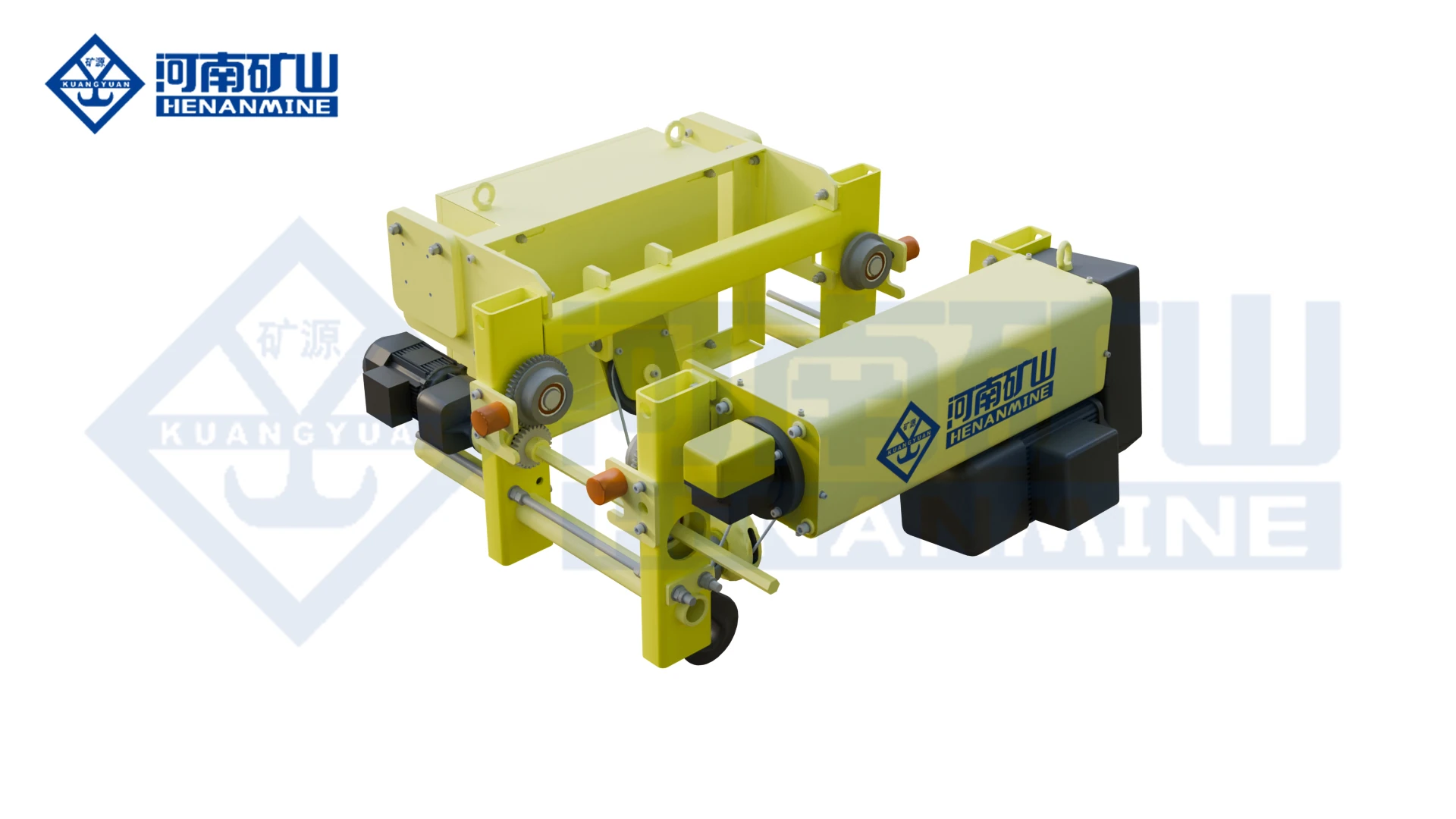
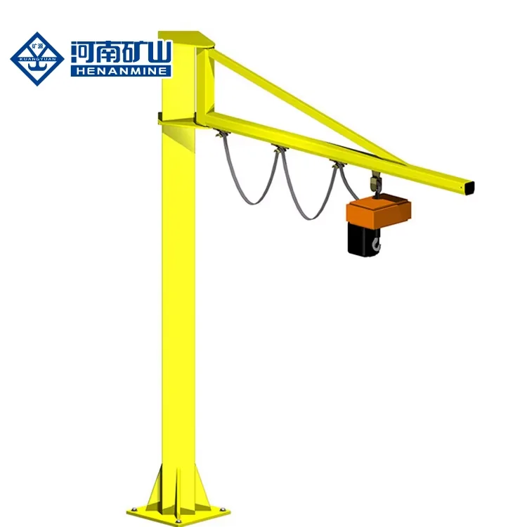
Wire rope lifting and pulling with a powered drum.
Explore Electric Winches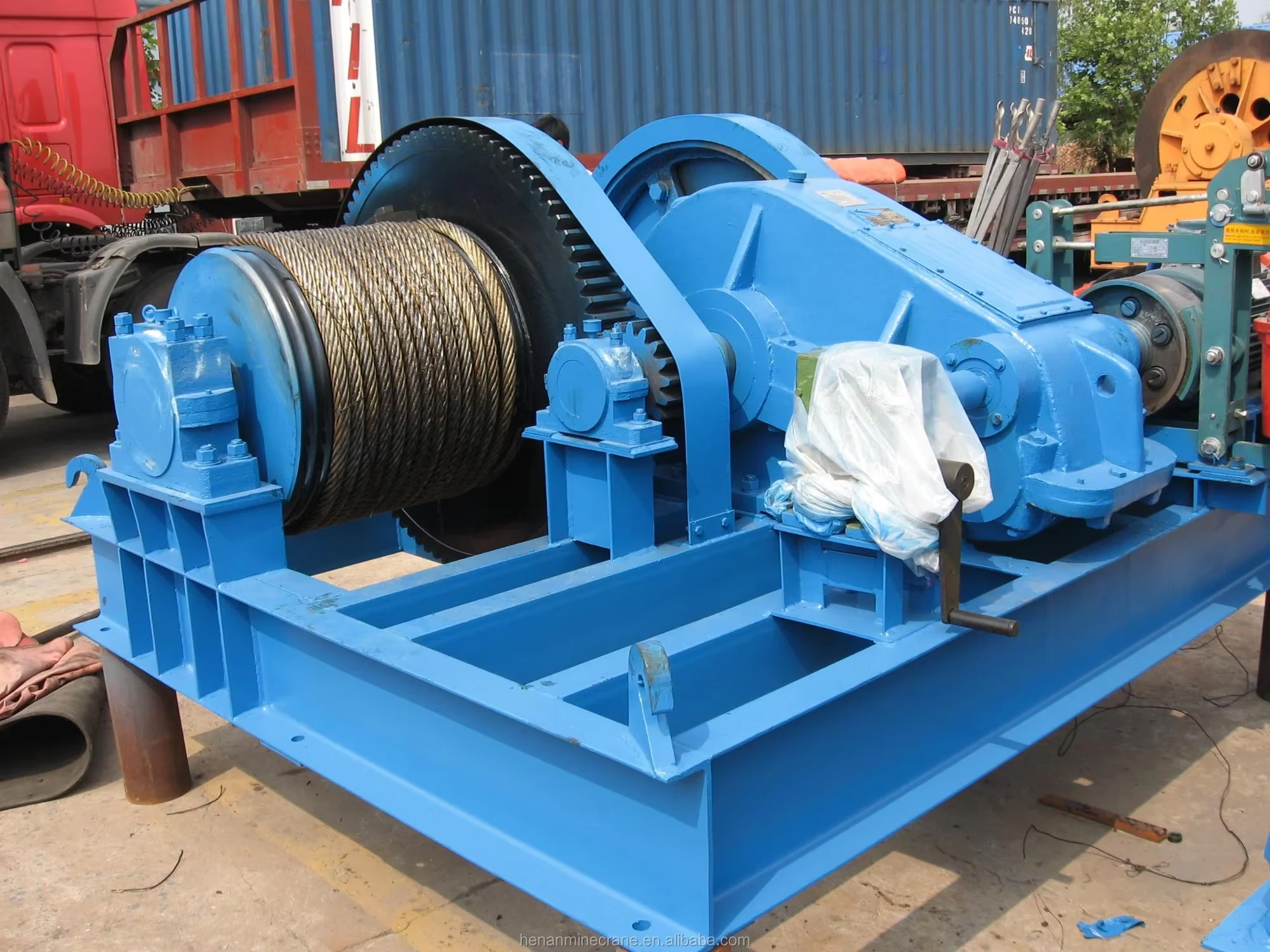
Grab buckets, magnets and hooks for your load.
Explore Lifting Attachments & Grabs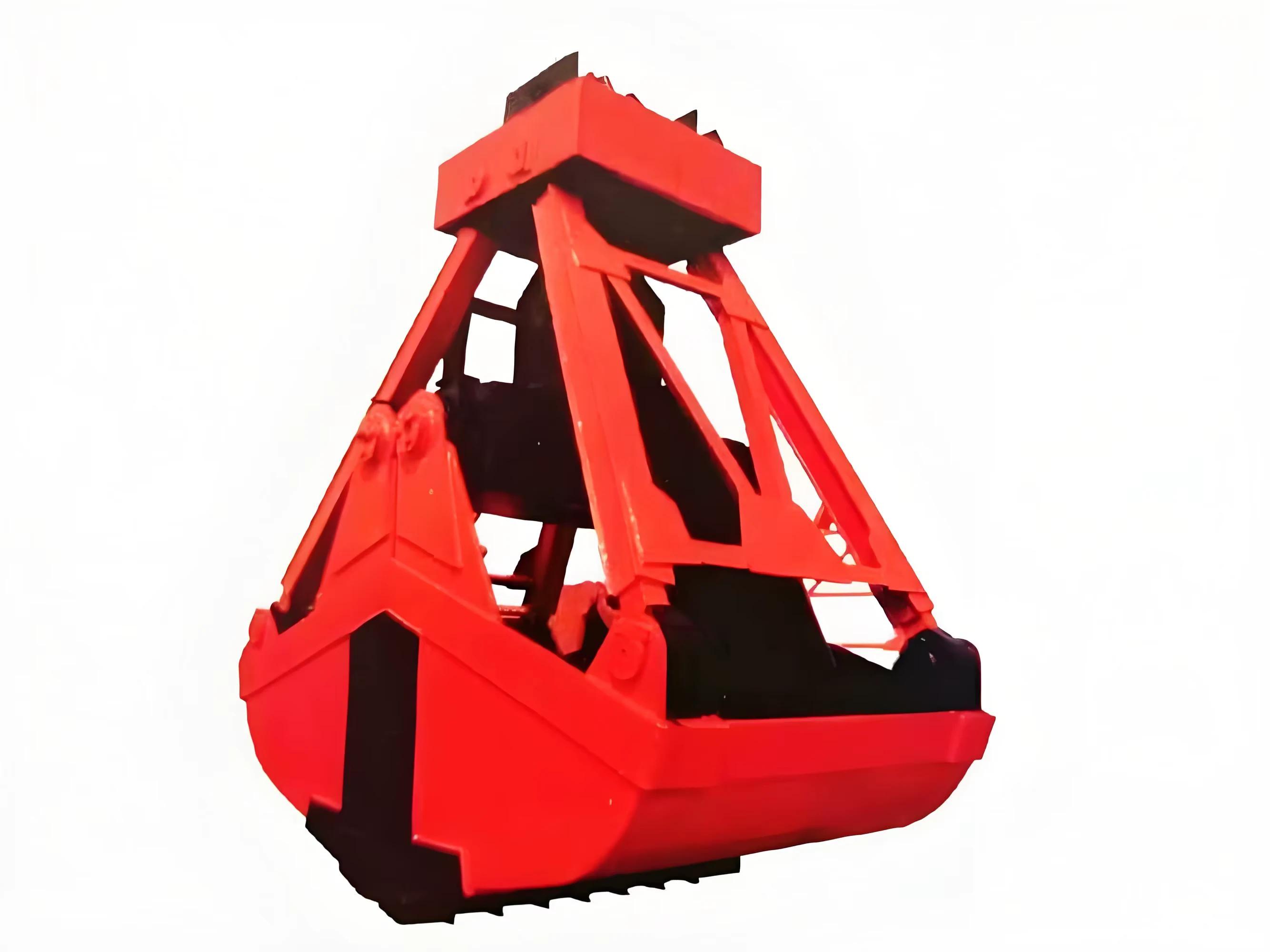
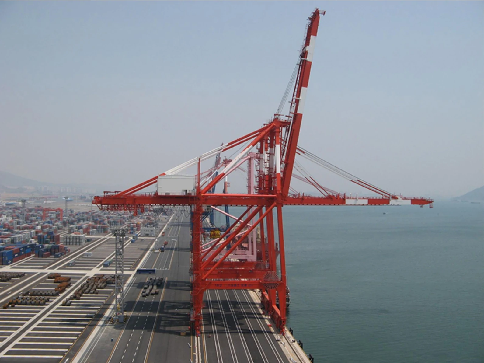
Mobile handling for containers, precast and yard loads.
Explore Rubber-Tired Gantry Cranes & Straddle Carriers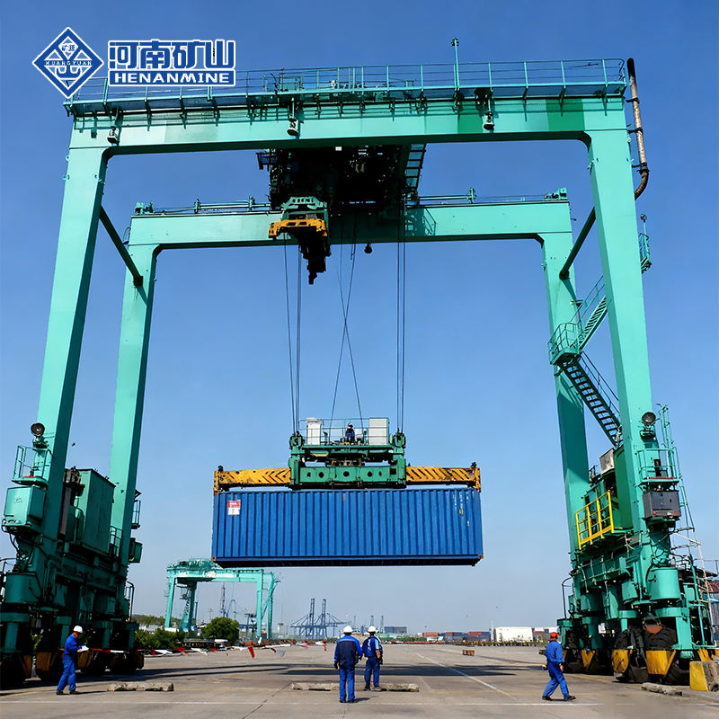
Lift and move vessels through boatyards and marinas.
Explore Marine Travel Lifts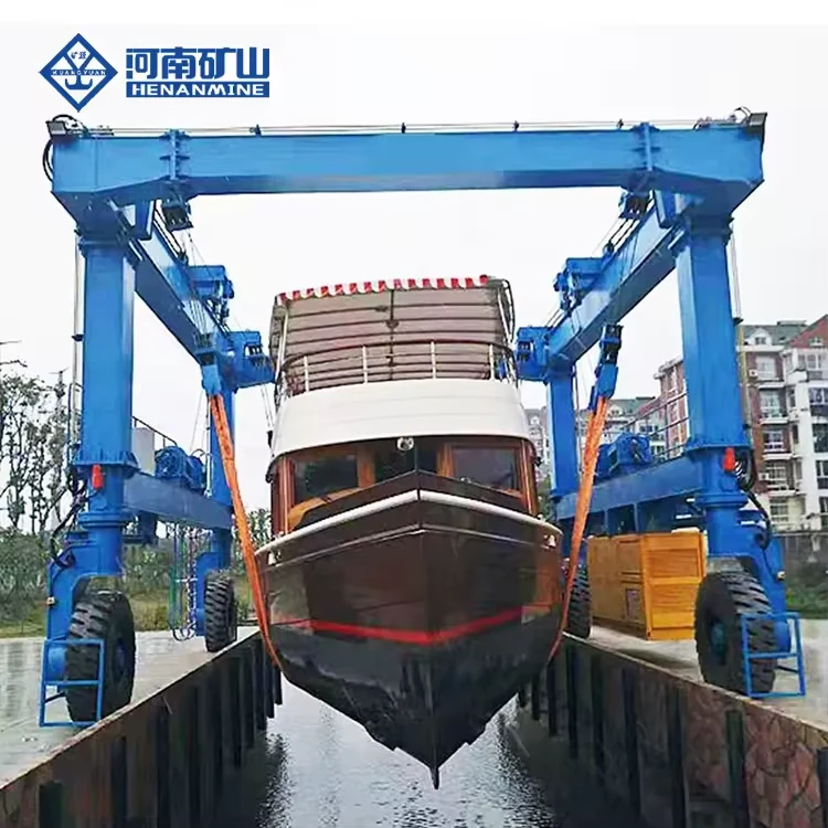
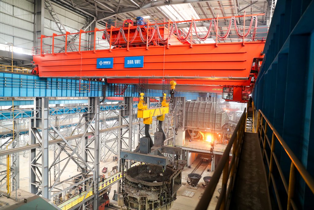
Ladle, slab, scrap and coil handling across steel production.
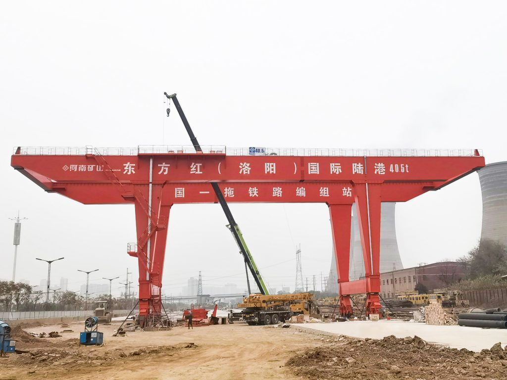
Container stacking and cargo transfers across terminals and rail.
Turbine installation, powerhouse maintenance and wind equipment assembly.
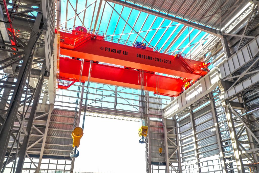
Controlled component transfer and positioning for precision assembly.
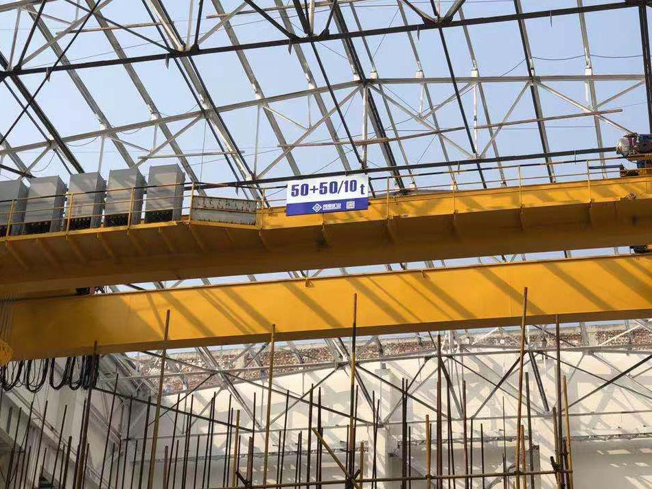
Heavy fabrication, production lifting and factory crane automation.
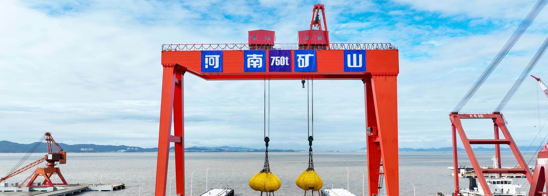
Process lifting for smelters, carbon blocks and anode materials.
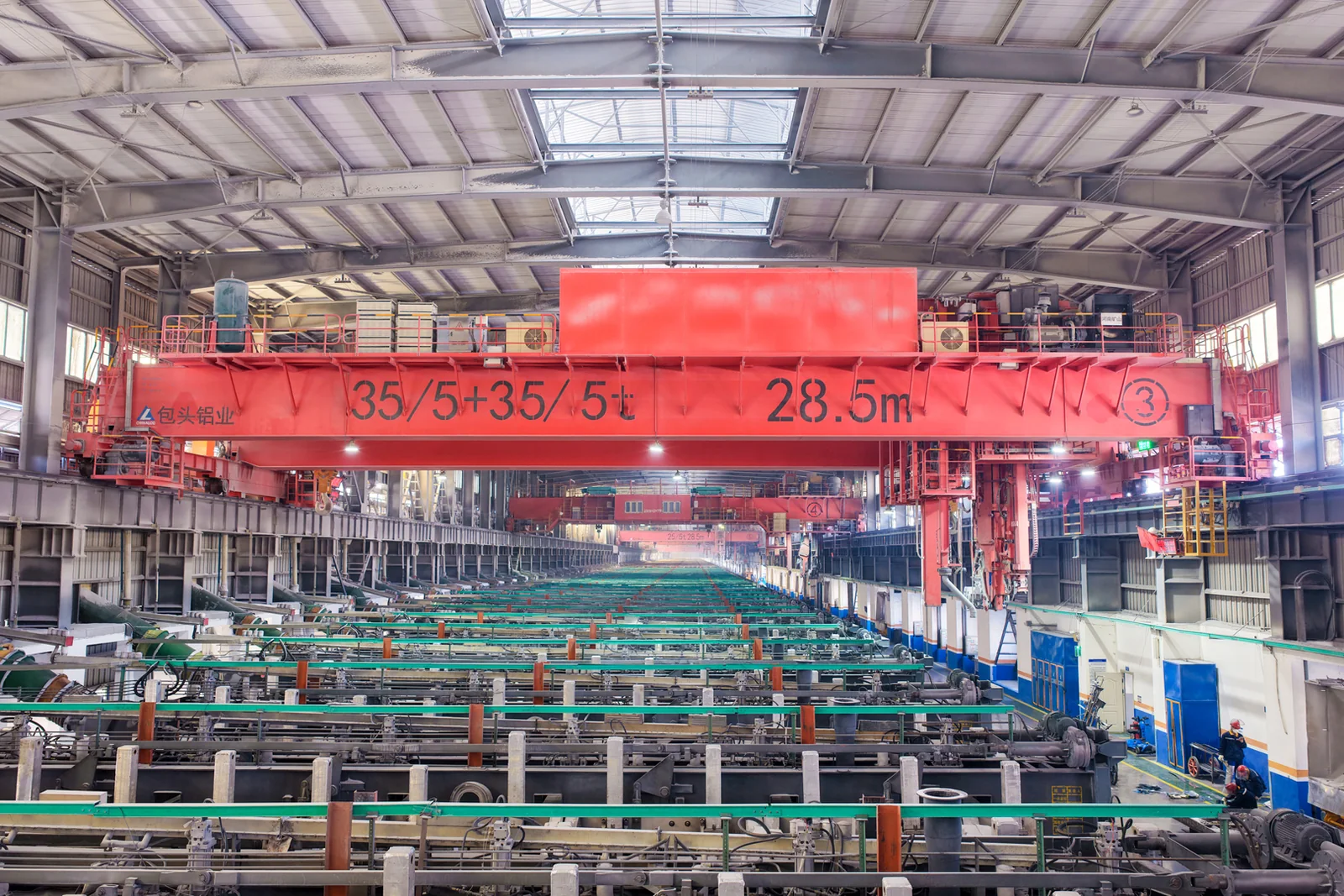
Clean lifting and classified protection for sensitive process areas.
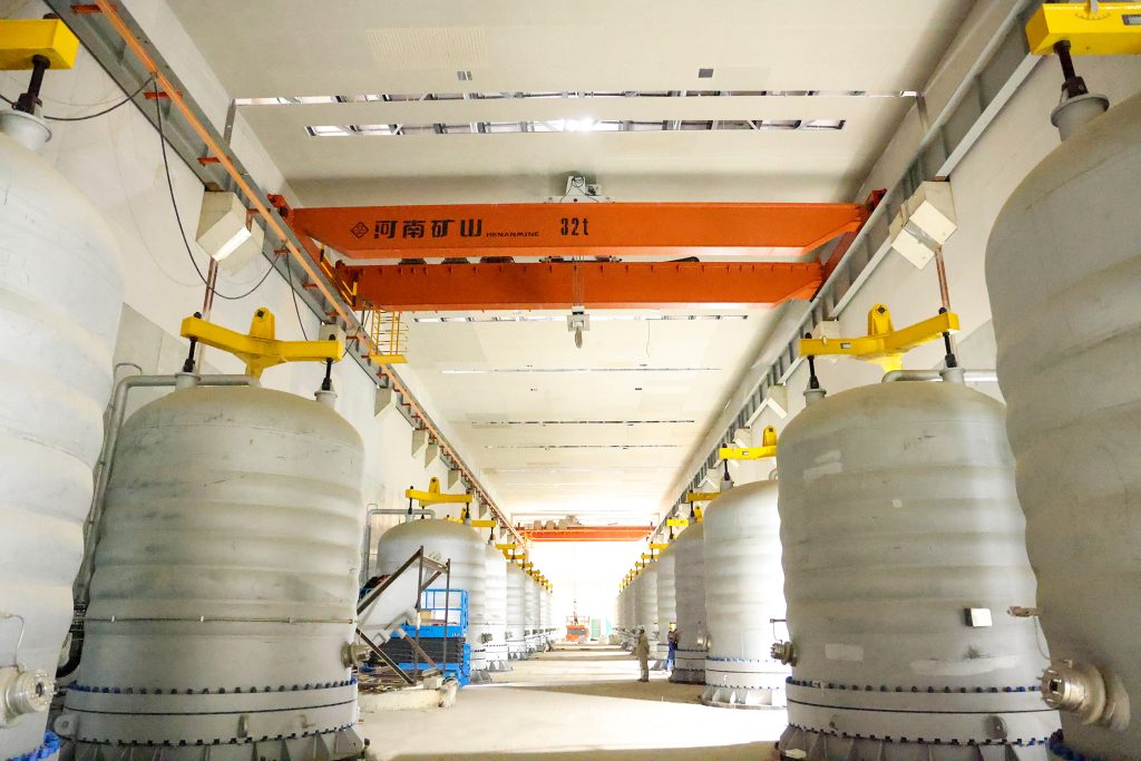
Bridge fabrication, metro construction and ship block assembly.
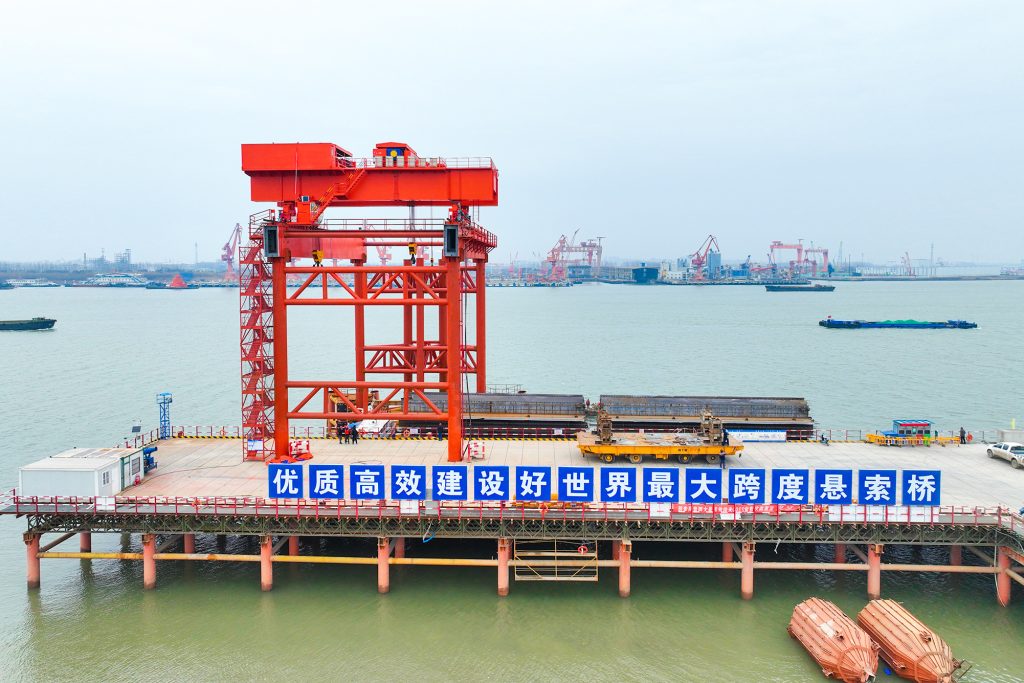
Automated storage and retrieval for plates, cables and bins.
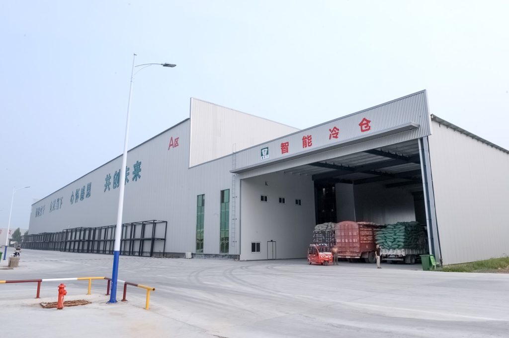
Follow project dispatches, crane engineering and factory acceptance.
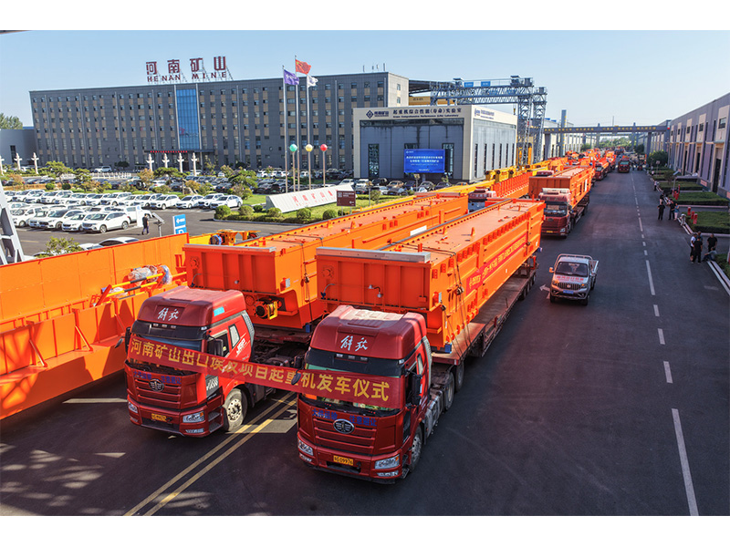
Dispatch, installation and equipment in service
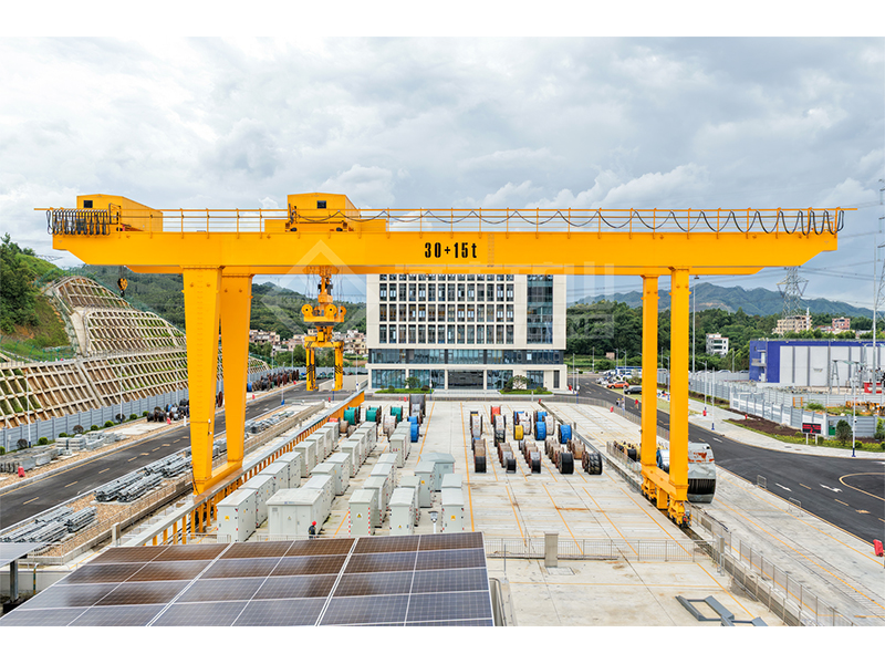
Crane configurations and handling technology
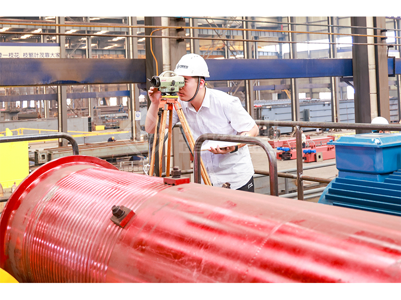
Factory inspections, acceptance and test programmes

Company developments, people and community programmes
Transfer filled ladles with a double-girder casting crane and separately rated auxiliary hook, configured for your pouring sequence.

Start with the information you already have. A load drawing and workshop sketch help us recommend a configuration.
Specify pickup spacing, connection dimensions, carrier mass and ladle balance together. These establish how the main lifting system connects to the vessel and how much complete suspended load the crane must carry.
Select the main and auxiliary lifting functions around their actual tasks. The reference package combines regulated hoisting with variable-frequency travel; the offer states the speeds and permitted movements needed at each station.
The matched configurations show load, span, lift and wheel load together. Use the ordered arrangement and load schedule to coordinate the carrier envelope, rail interface and supporting structure.

Carry filled or empty ladles between defined production positions. Check the carrier-to-ladle fit, route clearance and station lifting levels alongside the gross suspended load.
Position the ladle over the receiving point and specify the auxiliary hook's part in the pouring operation. The carrier geometry, tipping connection and permitted movement are selected as one handling arrangement.
Match the crane to charging or casting positions that require a compatible ladle carrier and auxiliary lifting function. State the approach clearances, process heat and repeat cycle the crane will encounter.
The main carrier and auxiliary hook have separate load limits. Their ratings are not additive, and any coordinated pouring movement is defined for the selected ladle and lifting geometry.
Compare the available options for your lifting task. Capacity, span, lift height and speed are matched in the selected configuration.
| Model | YZ double girder casting overhead crane |
|---|---|
| Reference main / auxiliary ratings | 100/32, 125/32, 140/40, 160/50 and 200/50 t; other project ratings can be specified |
| Reference rail-centre spans | 19, 22 and 25 m; available combinations shown below |
| Reference main lifting heights | 18–25 m, according to combination |
| Reference auxiliary lifting heights | 20–27 m, according to combination |
| Working class | A7 reference arrangement; duty matched to actual molten-metal cycle |
| Bridge / trolley form | Double girder bridge with main and auxiliary lifting functions on the selected trolley arrangement |
| Main load-handling device | Gantry-type ladle carrier matched to the ladle lifting interfaces |
| Auxiliary load-handling device | Hook for the specified auxiliary or ladle-tipping duty |
| Hoist control | Stator-voltage speed regulation in the reference package; selected speeds stated in the offer |
| Travel control | Variable-frequency speed control; selected trolley and bridge speeds stated in the offer |
| Upper hoist protection | Dual upper overtravel protection; final device arrangement specified in the safety schedule |
| Controls | PLC / HMI and master controller with zero-position return and locking |
| Thermal protection | Main/end-girder and selected component heat protection for the specified exposure |
| Reference maximum wheel load | 404–665 kN; combination and wheel arrangement dependent |
| Reference crane runway rail | QU120 for the listed combinations |
| Reference power supply | 380 V / 50 Hz / 3-phase AC; destination supply defined in the offer |
| Minimum order | 1 complete crane or a project batch |
| Main / aux load (t) | Span (m) | Max main lift (m) | Max aux lift (m) | Max wheel load (kN) | Crane rail |
|---|---|---|---|---|---|
| 100/32 | 19 | 18 | 20 | 520 | QU120 |
| 100/32 | 22 | 20 | 22 | 530 | QU120 |
| 100/32 | 25 | 25 | 27 | 545 | QU120 |
| 125/32 | 19 | 24 | 26 | 580 | QU120 |
| 125/32 | 22 | 20 | 22 | 595 | QU120 |
| 140/40 | 19 | 23 | 25 | 640 | QU120 |
| 140/40 | 22 | 23 | 25 | 650 | QU120 |
| 140/40 | 25 | 23 | 25 | 665 | QU120 |
| 160/50 | 19 | 24 | 26 | 404 | QU120 |
| 160/50 | 22 | 24 | 26 | 412 | QU120 |
| 160/50 | 25 | 24 | 26 | 420 | QU120 |
| 200/50 | 19 | 24 | 26 | 505 | QU120 |
| 200/50 | 22 | 24 | 26 | 515 | QU120 |
| 200/50 | 25 | 24 | 26 | 530 | QU120 |
A7 reference combinations with 380 V / 50 Hz / 3-phase AC. Main and auxiliary ratings are separate and not additive. Wheel loads depend on the wheel arrangement and load position; use the ordered layout for runway coordination. Hoist, trolley and bridge speed values and any modified dimensions are specified in the technical offer.
Compare the equipment views with your ladle drawing and process layout. The final general arrangement should identify carrier pickup spacing, hook positions, approach distances, service access and the dimensions required by the building team.
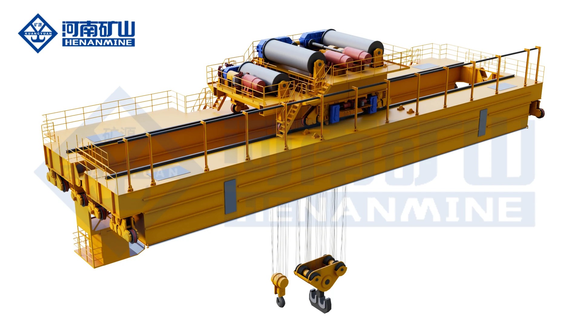

Compare the published paired load-and-span combinations as complete reference arrangements. Match the selected main and auxiliary heights, carrier geometry and wheel-load schedule to the station layout before releasing the crane for manufacture.
Include metal, ladle, carrier and all suspended accessories. Provide the ladle lifting interfaces, pickup spacing and centre of gravity so the carrier and main hoisting arrangement can be dimensioned together.
Identify whether the auxiliary hook assists pouring, handles an empty ladle or performs another defined task. Its load, connection, travel and relationship to the main carrier must cover that movement without treating the two ratings as extra combined capacity.
Supply pickup, transfer, pouring and set-down levels with the surrounding obstructions. Confirm both lifting heights and horizontal approaches on the ordered arrangement, rather than selecting lift height from a family-wide range.
The reference arrangement uses stator-voltage hoist speed regulation and variable-frequency travel. Give required loaded speeds, approach behavior and cycle time so the offer defines actual speeds, operator controls and any alternative drive package.
Describe radiant heat, ambient conditions and exposure time. Specify the brake, dual upper overtravel protection, monitoring and control functions in a safety schedule matched to the intended molten-metal operation.
The listed configurations use QU120 runway rail, with wheel loads that depend on the selected arrangement. Request the final wheel-load and rail drawing, maintenance access and destination electrical supply for building and installation coordination.
Request one itemized YZ scope covering the bridge, lifting arrangement, main ladle carrier, auxiliary hook, heat protection and controls. Include the required drawings, tests and site services so technical comparison and purchase approval use the same basis.
Identify the bridge, lifting mechanisms, lifting attachment, heat protection, controls and power feed. State the selected operating modes and equipment boundaries in the offer.
Request the arrangement, lifting-interface drawing, load-and-motion schedule, electrical information, safety-function description and agreed factory/site checks for the ordered crane.
List rails, runway steelwork, attachments, automation, weighing, spares, packing, freight, erection and commissioning as included, optional or excluded.
Agree drawing approval, manufacturing, testing and dispatch milestones for the selected configuration. Include access, shutdown windows and the destination in the delivery plan.
Define erection supervision, power and runway preparation, protection checks, attachment fit, trial operation and operator training, with responsibilities agreed before site work.
Record the warranty terms and commencement, service arrangements and recommended brake, rope, drive, control and attachment spares for the equipment supplied.
Agree load, lifting device, route, duty, thermal conditions and operating modes.
Coordinate hook coverage, attachment fit, runway reactions and site responsibilities.
Complete the agreed checks and records, then coordinate packing and shipment.
Confirm erection, commissioning, operator training and service arrangements.
Technical schedule · General arrangement · Attachment interface · Runway loads · Electrical information · Safety-function description · Agreed inspection records · Operation and maintenance manuals
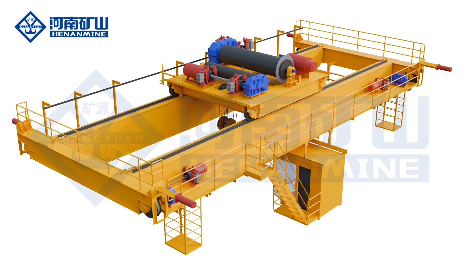
Move ladles through foundry and smelting bays with a metallurgical winch trolley and selected single-hook or main/auxiliary arrangement.
View this arrangement ↗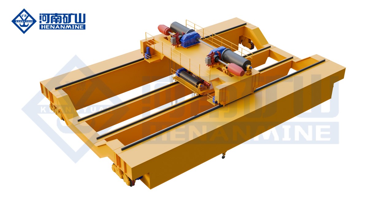
Give heavy ladle handling separate main and auxiliary lifting positions on a four-girder casting bridge. YZS uses independently travelling main and auxiliary trolleys, with their loads, spacing and permitted movements selected for the process. Compare nine A7 reference configurations, then coordinate the lifting attachments, hook envelope, runway reactions and safety controls as one engineered system.
View this arrangement ↗
Transfer filled ladles between foundry stations with a double-girder bridge and dedicated metallurgical electric hoist.
View this arrangement ↗Review the lifting task, configuration and quotation scope. We can help develop a crane proposal from the project information available.
YZ combines a double-girder bridge, gantry-type main ladle carrier and auxiliary hook for the specified ladle-transfer and casting task. The selected crane also needs the correct thermal, hoisting-safety and control package. State the complete molten-metal operation in the technical agreement.
Include the metal, empty ladle, carrier and every suspended attachment or accessory. A metal-production tonnage alone is not the crane's total suspended load. Supply the ladle interfaces and intended movements so the carrier and main rating can be checked together.
No. It identifies a 200 t main rating and a separate 50 t auxiliary rating. It does not authorize a 250 t combined lift. Loads, operating positions and any coordinated use of the main and auxiliary functions require their own agreed arrangement.
Provide the ladle drawing, pickup or trunnion spacing, connection dimensions, empty and filled weights and centre-of-gravity information. Include the required handling and pouring movement. The carrier drawing should show how these interfaces connect to the main lifting system.
A compatible pouring arrangement can be specified. Give the ladle tipping connection, required rotation or movement and receiving-station layout. The auxiliary load, hook reach and relation to the main carrier are defined for that sequence; a separate hook rating alone does not establish the pouring geometry.
The table lists 100/32, 125/32, 140/40, 160/50 and 200/50 t reference arrangements, with the span and main/auxiliary lift values paired in each row. The listed spans are 19, 22 or 25 m, depending on the arrangement. Other project ratings or dimensions need a confirmed technical schedule.
The wheel system and load distribution can differ between arrangements. Wheel load therefore cannot be scaled directly from nominal capacity. Use the final crane layout, wheel arrangement and load positions to coordinate the runway and supporting structure.
No universal speed is stated for the whole family. The reference package uses stator-voltage hoist regulation and variable-frequency travel; the technical offer specifies selected hoist, trolley and bridge speeds. Describe your loaded travel, final approach and cycle requirements when requesting a quotation.
YZ is the double-girder casting arrangement. YZS uses four girders with separate main and auxiliary trolleys. Compare the ladle interfaces, two lifting functions, required trolley positions, building clearances and runway reactions as complete systems. Shared nominal tonnage is only one part of that decision.
Confirm the complete suspended load, ladle carrier and auxiliary task, paired layout, heat and safety package, controls, wheel loads and acceptance tests. The written offer should also define equipment exclusions, destination documents, production milestones, installation support, warranty terms and spares. One complete crane or a project batch can be quoted.
Send your filled-ladle weight, ladle drawing and approximate runway span. Tell us whether the auxiliary hook will assist pouring or serve another task, and include a bay sketch if the station heights are still being developed.
info@cranehenanmine.com