Skip to content
CRANE MANUFACTURER SINCE 2002
info@hnksglobal.com+86 188 3620 7779Project enquiry ↗
Henan Mine Crane Request a quote
Complete Semi-Gantry Product Family

Semi-Gantry Cranes

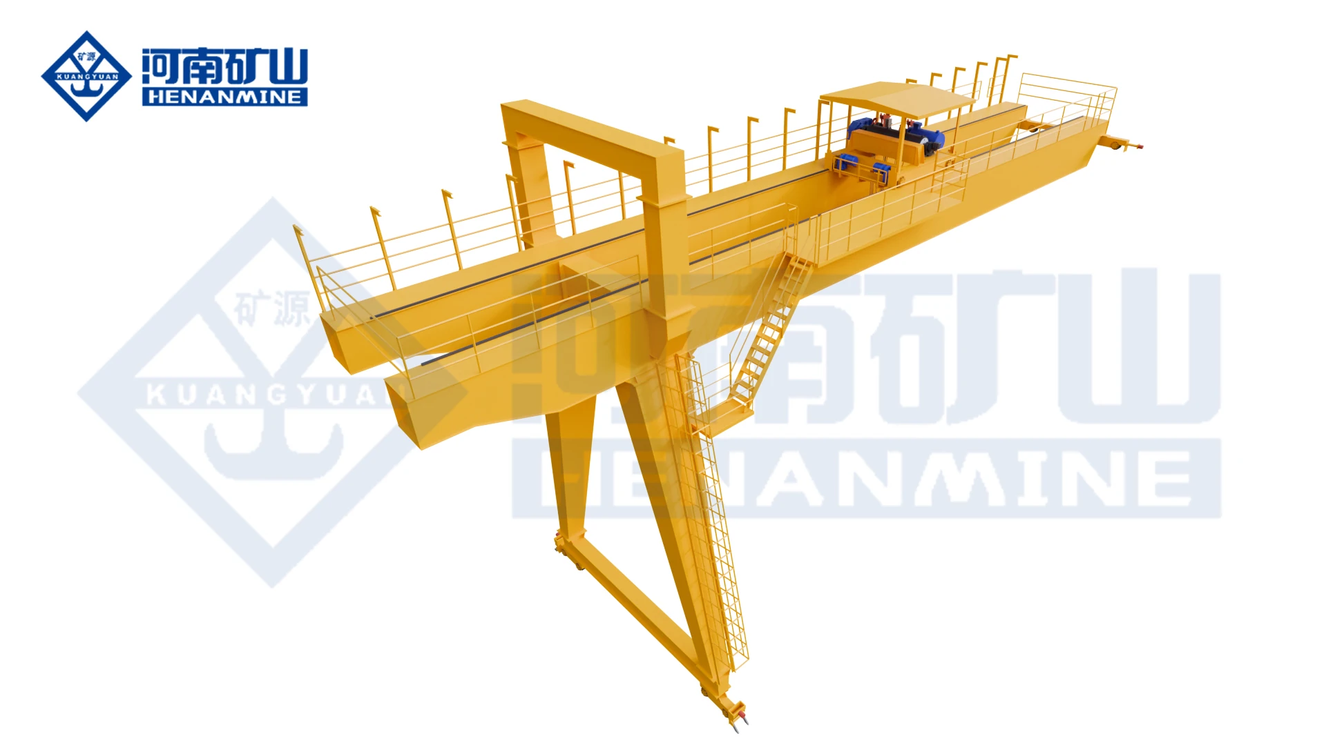
Semi-gantry crane systems for wall-side production, warehouse edges, narrow industrial bays and facilities where one side of the lifting area can use an existing elevated runway while the opposite side runs on a ground rail. The Henan Mine Crane range includes MGB hook, MGBE double-trolley, KSMB new electric-hoist, MB₁ double-main-girder electric-hoist and MBES new double-main-girder configurations.

Henan Mine Crane semi-gantry crane
5 Confirmed FamiliesSemi-Gantry Crane Range
General / Electric HoistHook, double-trolley and hoist-based systems
A3–A8 duty range across Gantry Crane Families
One Ground SideUses existing elevated/building-side runway where suitable
Product Family Structure

Complete Semi-Gantry Crane Range

The key selection decision is not only capacity. The building-side runway elevation, wall or column structure, ground-side rail position, floor traffic, available headroom and required lifting mechanism determine whether a general MGB/MGBE or an electric-hoist KSMB/MB₁/MBES configuration is appropriate.

General-Purpose Semi-Gantry Cranes

General-Purpose Semi-Gantry Cranes

Hook and double-trolley semi-gantry systems for wall-side heavy lifting and multi-point handling.

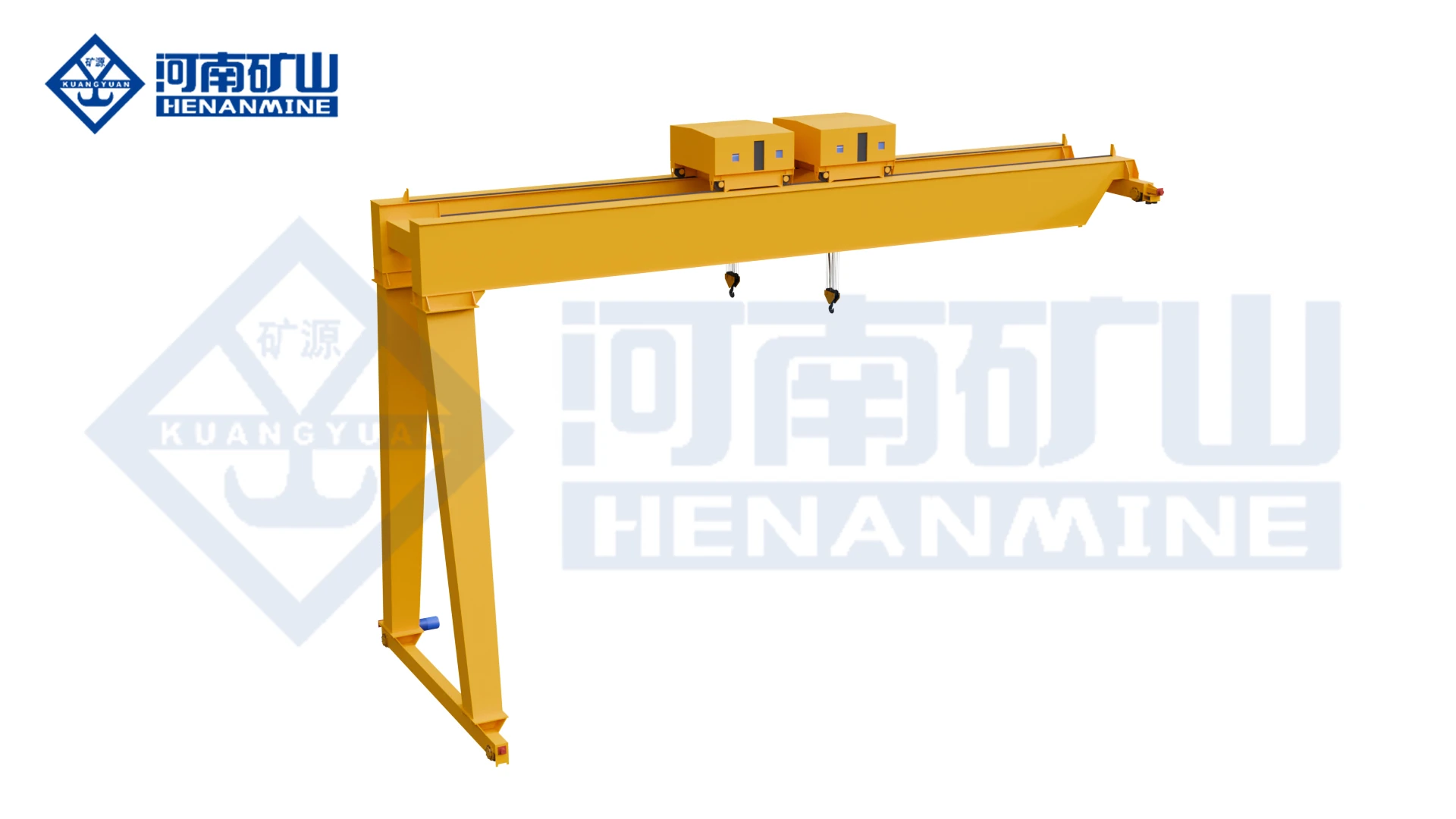
MGB Double-Girder Hook Semi-Gantry Crane
MGB

MGB Double-Girder Hook Semi-Gantry Crane

A hook-type semi-gantry crane developed from a conventional double-girder gantry crane. One side of the crane can use an elevated runway supported by the existing building while the opposite side runs on a ground rail, allowing wall-side handling without a full two-leg gantry structure.

Double GirderHookWall-Side HandlingSpace Saving
Technical Specifications
Type-Test ModelMGB
Type-Test ProductGeneral Gantry Crane
StructureSemi-gantry developed from a double-girder gantry crane
Lifting DeviceHook
Primary LayoutOne ground-side leg / runway + one elevated building-side runway
Main AdvantageUses wall-side and rack-side working zones while eliminating one full ground-supported leg line
Infrastructure BenefitLower ground-foundation requirement than a comparable full double-girder gantry crane
Typical UseWorkshop wall side, warehouse rack edge, railway-platform side and restricted industrial bays
Capacity / Span / HeightProject-specific; final values require site and load data
MGBE Double-Trolley Semi-Gantry Crane
MGBE

MGBE Double-Trolley Semi-Gantry Crane

A double-trolley semi-gantry crane for production areas that need two lifting positions while only one side of the crane can use a ground-supported gantry leg. The two trolleys support separate workstations or coordinated lifting of long and oversized loads.

Double TrolleyA3–A8Multi-Crane LinkageVFD
Technical Specifications
Type-Test ModelMGBE
Type-Test ProductGeneral Gantry Crane
Trolley Quantity2
Working ClassA3–A8
Travel ControlVariable-frequency control
Communication5G or industrial-Ethernet information synchronization for multi-crane coordinated operation
OperationTwo lifting positions for independent or process-coordinated handling
Primary LayoutSemi-gantry: building-supported/elevated side + ground-running side
Typical UseLong components, wall-side production, side bays and multi-point handling
Electric-Hoist Semi-Gantry Cranes

Electric-Hoist Semi-Gantry Cranes

Compact electric-hoist semi-gantry systems for light-to-medium industrial duty, low buildings and modern side-bay handling.

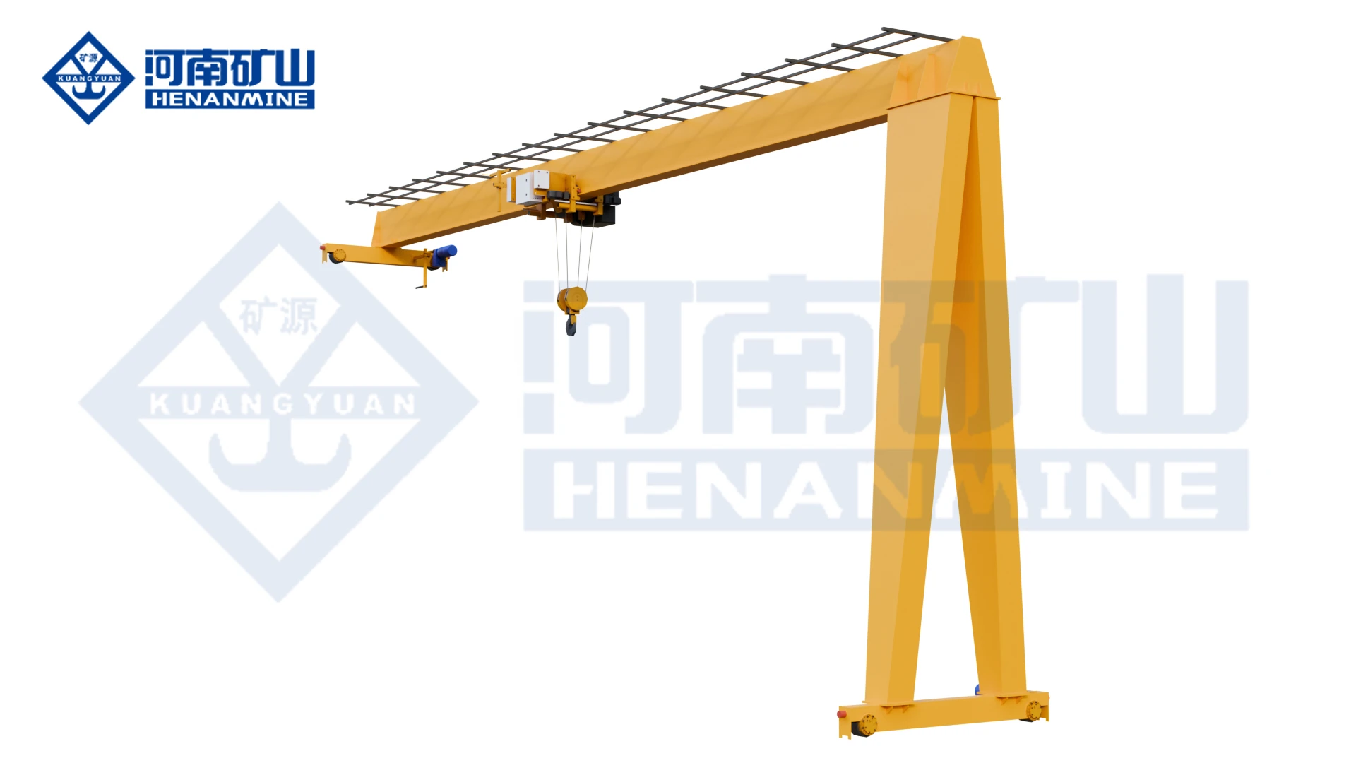
KSMB New Electric-Hoist Semi-Gantry Crane
KSMB

KSMB New Electric-Hoist Semi-Gantry Crane

A new-generation electric-hoist semi-gantry crane combining lightweight structure, variable-frequency motion and compact dimensions. It is designed for modern factories where one side of the lifting area can use the existing building runway and floor space must remain open.

A3–A5New Generation1:10 Speed RegulationLightweight
Technical Specifications
Type-Test ModelKSMB
Type-Test ProductElectric Hoist Gantry Crane
Working ClassA3–A5
Lifting MechanismElectric hoist
Lifting AttachmentsHook / grab / electromagnetic attachment according to project
Speed ControlVFD; heavy-load slow / light-load fast
Speed Regulation Range1:10
Lightweight Reduction15–30% vs traditional crane
Max. Wheel-Load Reduction20–35%
Energy Reduction10–20%
Travel DriveThree-in-one direct-drive travel mechanism
ControlCabin / pendant / wireless remote / PLC linkage
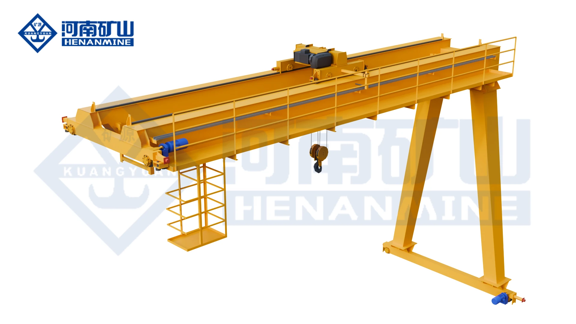
MB₁ Double-Main-Girder Electric-Hoist Semi-Gantry Crane
MB₁

MB₁ Double-Main-Girder Electric-Hoist Semi-Gantry Crane

A compact double-main-girder electric-hoist semi-gantry crane for low workshops, narrow aisles and wall-side material handling. The double-main-girder structure improves bridge rigidity while the semi-gantry runway arrangement reduces the floor area needed for support structures.

Double Main GirderA3–A5Electric HoistCompact Layout
Technical Specifications
Type-Test ModelMB₁
Type-Test ProductElectric Hoist Gantry Crane
Main StructureDouble main girder semi-gantry
Working ClassA3–A5
Lifting MechanismElectric hoist
Travel DriveThree-in-one direct-drive travel mechanism
ControlCabin / pendant / wireless remote / PLC linkage
Structural CharacterCompact overall height and external dimensions
Typical UseLow workshops, narrow passages, warehouse side bays and wall-adjacent production areas
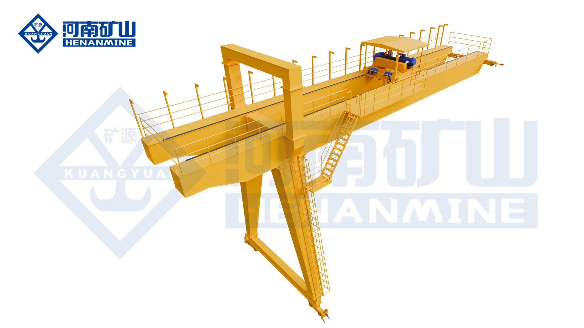
MBES New Double-Main-Girder Electric-Hoist Semi-Gantry Crane
MBES

MBES New Double-Main-Girder Electric-Hoist Semi-Gantry Crane

A new double-main-girder electric-hoist semi-gantry crane for restricted industrial spaces. It combines a compact double-girder bridge, electric-hoist lifting and three-in-one travel drive for wall-side or building-edge work areas where a complete gantry structure is unnecessary.

New TypeDouble Main GirderA3–A5Electric Hoist
Technical Specifications
Type-Test ModelMBES
Type-Test ProductElectric Hoist Gantry Crane
Main StructureNew double-main-girder semi-gantry
Working ClassA3–A5
Lifting MechanismElectric hoist
Travel DriveThree-in-one direct-drive travel mechanism
ControlPendant / wireless remote
Structural CharacterCompact overall height and dimensions for restricted spaces
Product ExampleAvailable configurations include a 50/10 t new double-main-girder semi-gantry example
Typical UseRestricted workshops, side bays, warehouse edges and production-line extensions
Side-by-Side Selection

Semi-Gantry Crane Model Comparison

Compare bridge structure, lifting mechanism and duty before checking the asymmetric runway reactions, building-side crane beam, ground rail and available working envelope.

Model / ConfigurationStructureLifting System DutyPrimary Direction
MGB
MGB Double-Girder Hook Semi-Gantry Crane
Semi-gantry developed from a double-girder gantry craneHookProject-specificSpace Saving
MGBE
MGBE Double-Trolley Semi-Gantry Crane
Semi-gantryProject-specificA3–A8VFD
KSMB
KSMB New Electric-Hoist Semi-Gantry Crane
Semi-gantryElectric hoistA3–A5Lightweight
MB₁
MB₁ Double-Main-Girder Electric-Hoist Semi-Gantry Crane
Double main girder semi-gantryElectric hoistA3–A5Compact Layout
MBES
MBES New Double-Main-Girder Electric-Hoist Semi-Gantry Crane
New double-main-girder semi-gantryElectric hoistA3–A5Electric Hoist
Semi-Gantry Layout

How a Semi-Gantry Crane Uses the Building

Building-Side Runway

One end of the crane travels on an elevated runway supported by the existing workshop structure or a dedicated elevated support line. The crane-beam capacity and column reactions must be verified before installation.

Ground-Side Leg & Rail

The opposite end uses a gantry leg running on a floor or foundation rail. Rail gauge, wheel load, foundation bearing capacity and floor traffic must be coordinated with production layout.

Asymmetric Structural Reactions

Because the two sides use different support elevations and structural systems, vertical, lateral and longitudinal reactions must be checked independently at the building-side runway and ground-side rail.

Current configuration Range

Double-Girder Electric-Hoist Semi-Gantry configuration Parameters

Henan Mine Crane's current international product data provides a general double-girder semi-gantry configuration range. Final MGB, MB₁ or MBES values remain project-specific and should be confirmed in the technical proposal.

ParameterconfigurationProcurement Relevance
Lifting Capacity3–20 t in technical table; 5–20 t shown in the headline rangeConfirms the standard electric-hoist semi-gantry family is primarily light-to-medium duty.
Span5–30 m technical; wider headline configurations can be customizedMust be matched to building-side runway centerline and ground-rail position.
Lifting Height6–18 m technicalControlled by workshop height, bridge depth and electric-hoist arrangement.
Working ClassA3–A6 configuration rangeChoose from actual lifts/hour, operating hours and load spectrum.
Hoisting Speed0.33–8 m/min; single / dual speed optionsDefines productivity and final positioning behavior.
Long Travel5–30 m/minRunway length and production flow determine suitable travel speed.
Trolley Travel2–20 m/minAffects load positioning across the working width.
Protection ClassIP54 electrical configurationShould be upgraded if dust, moisture or corrosive exposure requires it.
Selection by Application

Choose the Semi-Gantry Crane by Workshop Condition

Wall-Side Material Handling

MGB is suited to conventional hook lifting where one side of the bay already has a usable elevated runway and the opposite side can support a ground rail.

Two Lifting Positions

MGBE provides two trolleys for independent workstations, long-load lifting or process coordination in a semi-gantry layout.

Modern Light / Medium Duty

KSMB uses lightweight design and VFD motion for factories prioritizing reduced wheel load, lower energy use and smooth positioning.

Higher Bridge Rigidity

MB₁ uses a double-main-girder electric-hoist structure where compact dimensions and higher bridge stiffness are both required.

Restricted Headroom

MB₁ and MBES emphasize compact height and external dimensions for low workshops and narrow passages.

Existing Factory Retrofit

Semi-gantry layouts can reduce site modification when the building-side runway is suitable, but the existing crane beam and columns must be structurally verified.

Engineering Requirements

Critical Semi-Gantry Crane Design Factors

Building-Side Crane Beam

Provide beam section, material, column spacing, runway elevation and allowable vertical/lateral reactions for the elevated side.

Ground Rail & Foundation

The gantry-leg side requires rail type, foundation width/depth, allowable bearing pressure and drainage information for outdoor or semi-outdoor layouts.

Differential Settlement

Building-side and ground-side supports can move differently. Level tolerance and settlement control are important to avoid skew and wheel binding.

Anti-Skew Travel

VFD travel and drive synchronization reduce racking when the two runway sides have different structural stiffness and support conditions.

Wall / Column Clearance

Hook approach, trolley envelope, electrical equipment and bridge end clearances must be checked against walls, columns, racks and services.

Indoor / Outdoor Interface

Where the crane serves both workshop and exterior areas, wind, rain, corrosion, rail drainage and cable routing should be included in the design.

Layout Comparison

Semi-Gantry vs Full Gantry vs Overhead Crane

Semi-Gantry vs Full Gantry

Semi-gantry eliminates one full ground-supported leg line and can reduce floor-space and foundation requirements when a suitable elevated building-side runway already exists. Full gantry remains more independent from the building structure and is preferred where both sides must be ground supported.

Semi-Gantry vs Overhead Crane

A conventional overhead crane relies on elevated runways on both sides. Semi-gantry is useful when only one side has a suitable elevated support or when adding a second elevated crane beam would be difficult or expensive.

Engineering RFQ

Request a Semi-Gantry Crane Proposal

Provide the maximum load, span, lifting height, runway length, existing building-side crane beam, ground-rail position, floor/foundation condition, working duty and required lifting mechanism. Existing-factory projects should include building drawings or crane-beam data.