Skip to content
Henan mine crane co., ltd. Get a project quote
Henan Mine Crane · Double-girder gantry systems

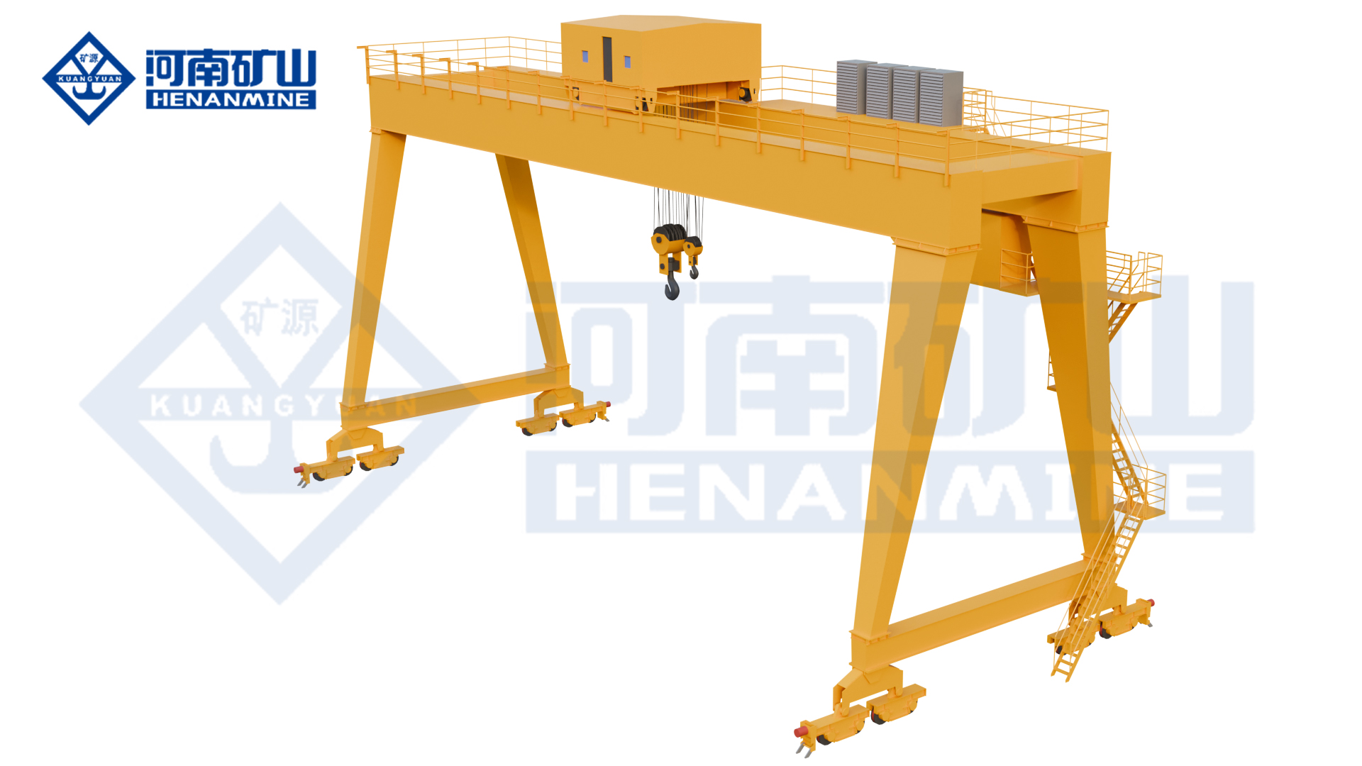
Double Girder Gantry Cranes

Double-girder gantry cranes use two main girders to support the lifting trolley over a work area. Compare hook, electric-hoist, double-trolley and process arrangements for your material, then match the useful hook positions and supporting runways to the load route. Full and semi-gantry layouts serve different site requirements.

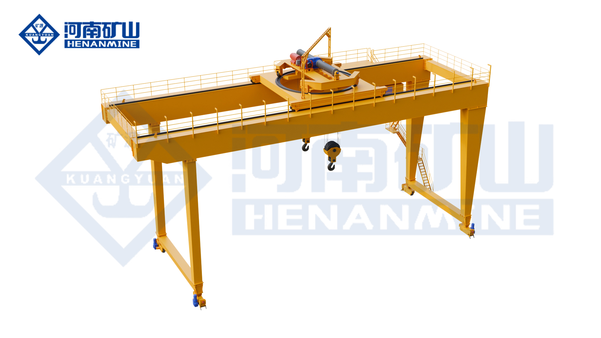
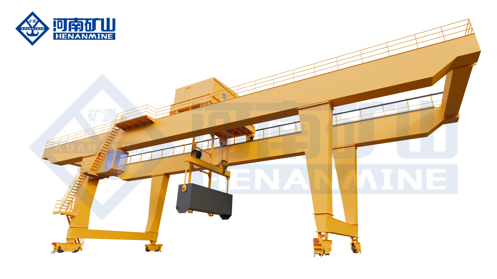
ME double-trolley double-girder gantry crane

Hook and Double Trolley Gantry Cranes

Compare MG for hook-handled cargo with ME where the work needs separated lifting points. Specify the complete load, operating cycle and permitted handling sequence.

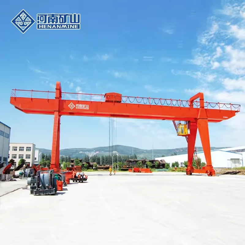
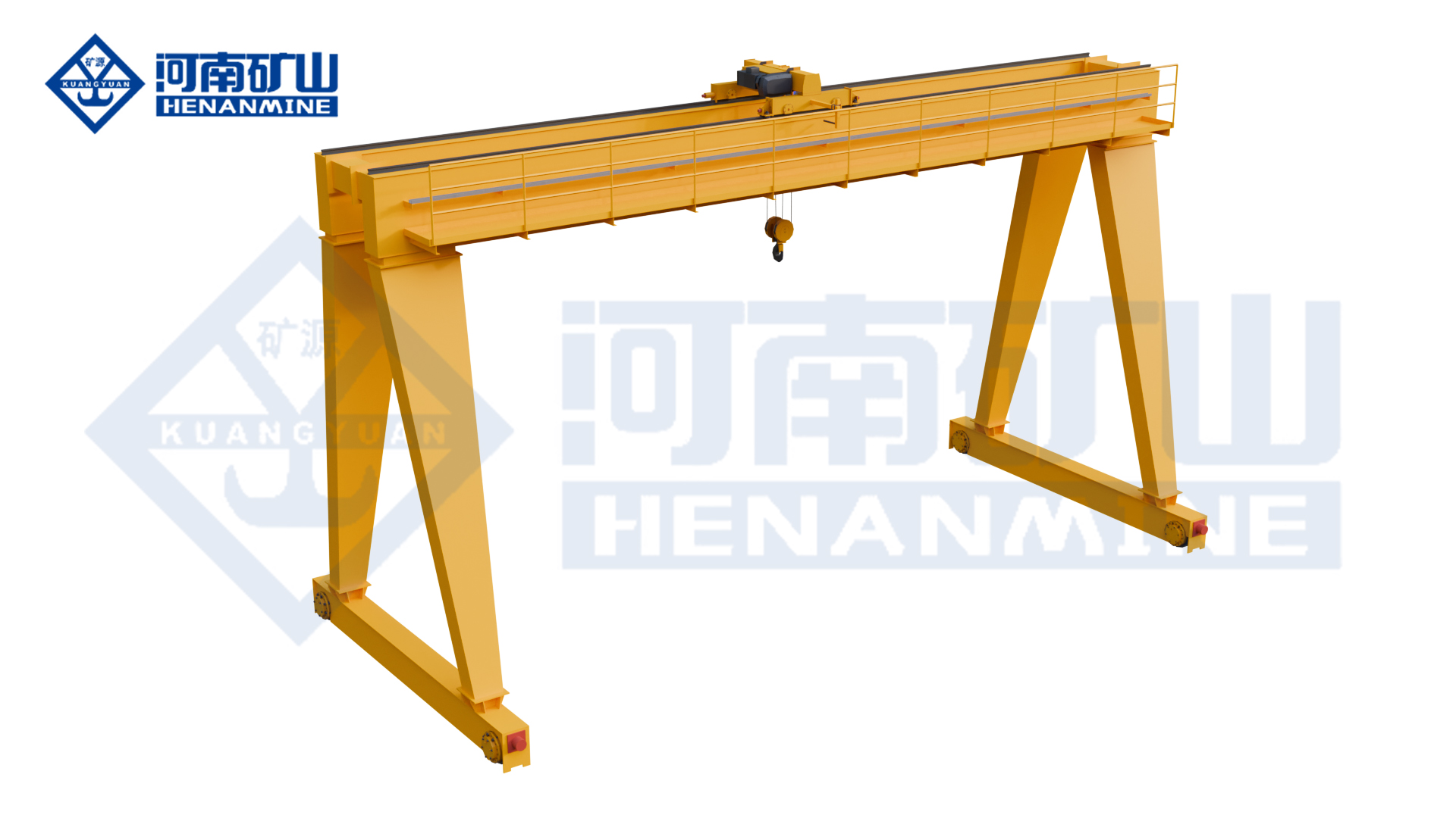
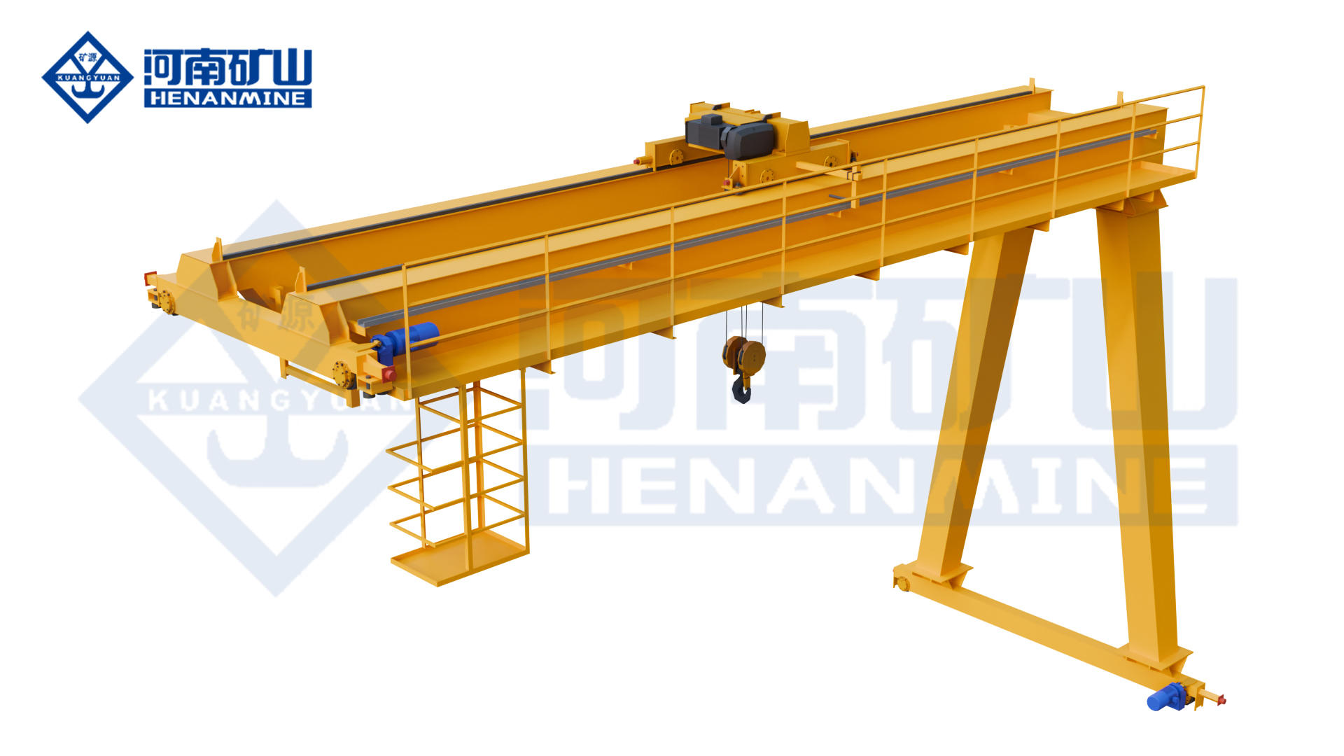
MG-series double-girder hook gantry crane in an outdoor yard
MG series

Double Girder Hook Gantry Crane (MG)

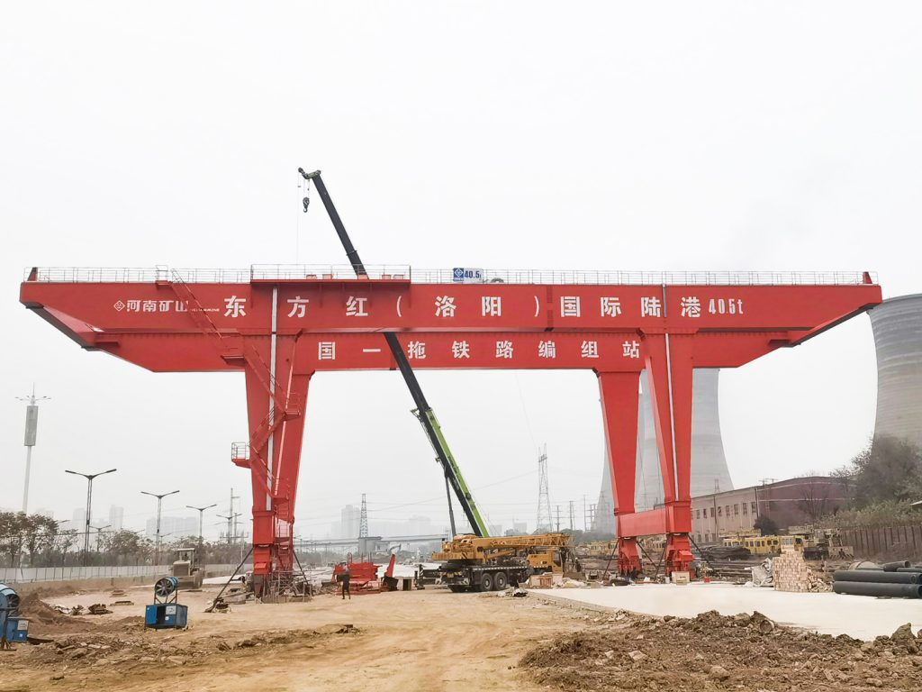
Outdoor yard loading and component handling with a hook trolley.

Handling systemHook lifting
RunwayGround rails, both sides
Capacity & spanSelected for the project
All specifications
Model specifications and configuration choices
ModelMG
Crane arrangementDouble-girder hook gantry
Lifting attachmentHook
Application focusOutdoor material handling; warehouses, factories and loading areas
Rated lifting capacitySelected for the complete suspended load, including lifting attachments and rigging
SpanRail-centre span selected for the working area
Lifting heightWorking lifting height selected for the pickup and placement levels
Working classSelected from load spectrum, lifts per hour and shifts
Hoisting packageMechanism, hook block and reeving identified for the selected load and lift
Lifting speedLoaded lifting and positioning speeds specified with the hoisting package
Trolley travelCross-travel speed and hook approaches selected for the transfer positions
Crane travelTravel speed and stopping control selected for the runway
Main / auxiliary hookHook capacities, heights and permitted operating modes specified where an auxiliary hook is required
Hook coverageLeg opening, end approach and any cantilever shown on the general arrangement
Operator controlsOperator position and control package selected for visibility and handling
Runway interfaceRail section, wheel loads and horizontal reactions provided for the selected crane
Electrical supplySite voltage, frequency, phases and power-feed route specified
Outdoor exposureWorking and parked wind conditions and corrosion exposure addressed in the equipment scope
Delivery arrangementTransport sections, assembly joints and site access agreed for the destination
Order quantityEnquire for one complete crane or a multi-crane project
ME double-trolley double-girder gantry crane
ME series

Double Trolley Gantry Crane (ME)

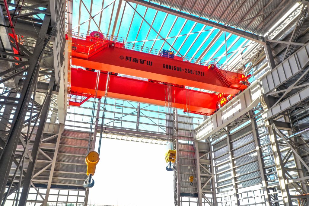
Two travelling trolleys for long components and planned two-point lifts.

Lifting trolleysTwo
Operating modesIndependent or joint
Working-class optionsA3–A8, selected to duty
All specifications
Model specifications and configuration choices
ModelME
Trolley arrangementTwo travelling lifting trolleys
Operating modesTrolleys can operate independently or jointly
Working-class rangeA3–A8; select the class for the operating cycle
Travel drivesThree-in-one direct-connected crane and trolley travel drives
Trolley feedbackEncoder-based double-trolley control
Drive controlVariable-frequency drive control with CI-card functionality
Cantilever arrangementOne side, both sides or no cantilever, according to the selected layout
Working motionsVertical lifting, cross travel and crane long travel
Rated lifting capacitySpecify the rating of each trolley and the permitted combined lifting load
SpanRail-centre span selected for the working area
Lifting heightWorking lifting height selected for the pickup and placement levels
Lifting-point spacingUsable trolley separation selected for the load geometry
Coordinated controlLoad sharing, positioning and permitted joint motions defined for the handling sequence
Projection warning lightHoisting-area projection light available by configuration
Lifting attachmentHook or other specified attachment matched to the handling task
Lifting and travel speedsWorking and positioning speeds specified for each motion
Operator controlsOperator position and independent / joint control functions specified
Electrical supplySite voltage, frequency, phases and power-feed route specified
Runway reactionsWheel-load and horizontal-reaction schedule supplied for the selected arrangement

Grab and Electromagnetic Gantry Cranes

Choose the pickup system for loose bulk material or suitable ferrous loads. Include the attachment mass, operating cycle and power or control interfaces in the crane selection.

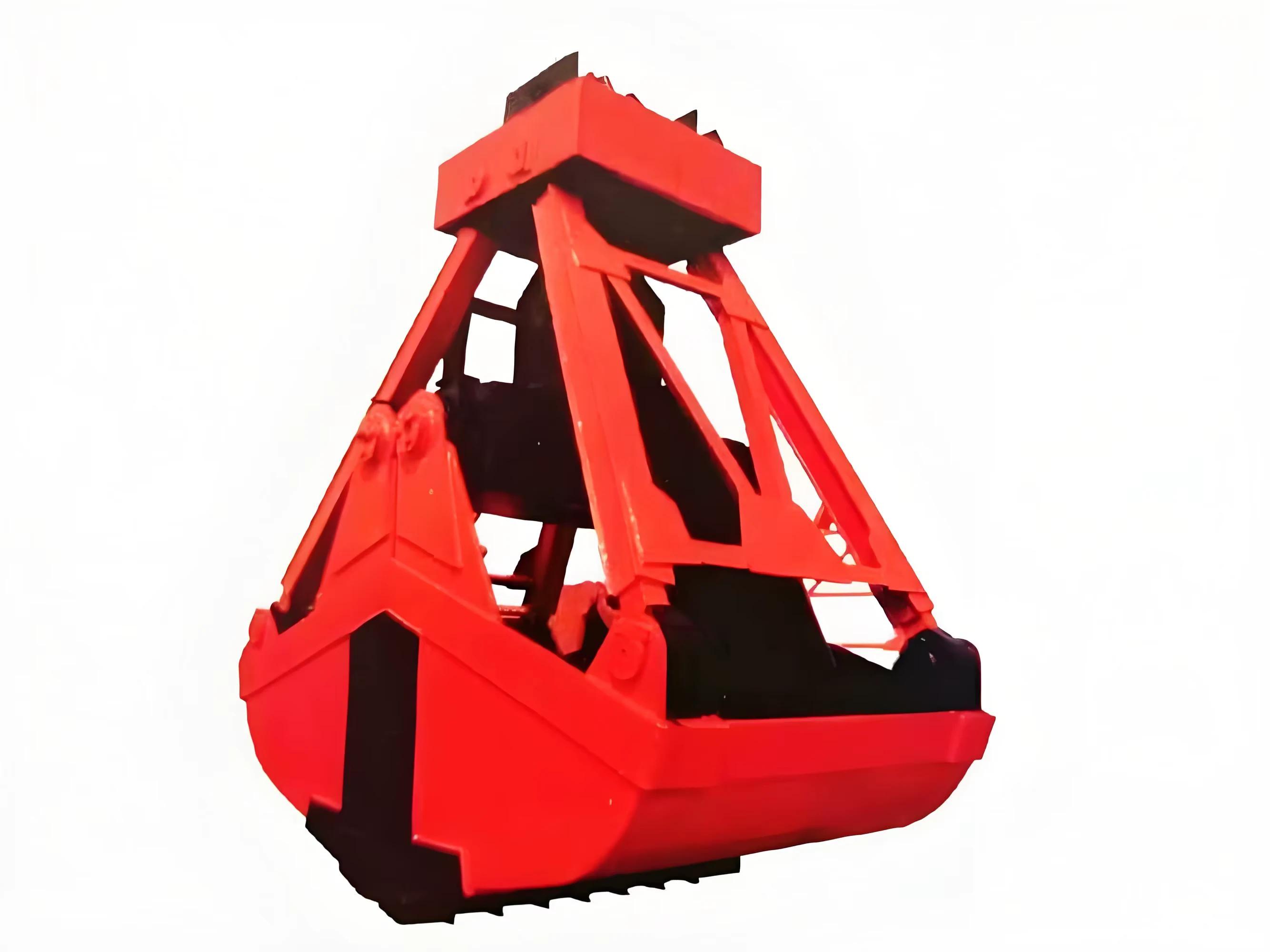
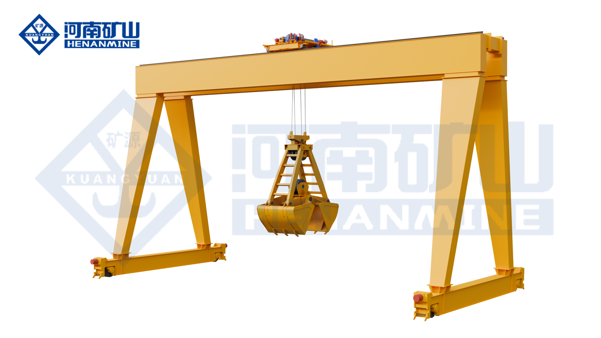
MZ double-girder gantry crane with a mechanical grab bucket
MZ series

Grab Bucket Gantry Crane (MZ)

Grab-bucket loading and unloading of loose bulk materials.

AttachmentDedicated grab
Reference load20 t suspended load
Reference span options18–35 m
All specifications
Model specifications and configuration choices
ModelMZ
Rated-load reference20 t; check the complete suspended load with the selected grab
Crane structureDouble-girder gantry frame
Primary attachmentGrab
Handling taskDedicated bulk-material loading and unloading
Runway arrangementLegs on both sides; ground-level rail travel
Working motionsGrab lifting, trolley cross travel and crane long travel
Structural designMain and end-girder stress distribution optimised by finite-element analysis
Rated suspended loadGrab self-weight plus material load and connecting equipment
Span options, reference package18–35 m; select the matched load/span arrangement
Maximum lift, reference package10 m; confirm the grab working levels
Grab volumeSelected from material density and the required load per cycle
Material propertiesSpecify density, particle size and flow characteristics
Bulk density, reference grab< 1.5 t/m³ for the stated grab package
Grab actuationHydraulic or mechanical opening / closing selected with the grab
Grab cycleOpening / closing speed and full handling cycle confirmed for the material and grab
Duty options, reference packageA6–A8; selected for the required load spectrum
Automation controlManual and automated operating functions specified in the control package
Authorised accessFingerprint-based operator access available by configuration
Camera systemMultiple camera views and operator display available by configuration
Lifting and travel speedsMotion speeds selected for pickup, transfer and controlled discharge
Electrical supplyCrane and grab power / control interfaces specified for the site
MC double-girder gantry crane and trolley arrangement
MC series

Electromagnetic Gantry Crane (MC)

Electromagnetic pickup of suitable ferrous scrap, billets and steel loads.

Lifting systemElectromagnetic
MaterialsSuitable ferrous loads
Motion controlVariable frequency
All specifications
Model specifications and configuration choices
ModelMC
Crane structureDouble-girder electromagnetic gantry
Lifting attachmentIntegrated electromagnetic lifting system
Material focusFerromagnetic material such as suitable scrap and steel billets
Motion controlVariable-frequency control throughout the crane
Structural arrangementModular crane design
WheelsForged wheels
Transmission couplingCrowned gear coupling
Rope drumRolled steel-plate drum
Protection functionsOverload protection, travel limits, buffers and wind protection
Cantilever arrangementOne side, both sides or no cantilever, according to the selected layout
Rated suspended loadMaterial plus magnet, suspension and connecting equipment
SpanRail-centre span selected for the working area
Lifting heightWorking lifting height selected for the pickup and placement levels
Magnet selectionMagnet arrangement selected for steel form, load condition and temperature
Magnet electrical packagePower supply, holding / release functions and any backup requirements defined in the offer
Working classSelected for the magnet handling cycle, load spectrum and shifts
Motion speedsLifting, trolley and crane-travel speeds specified for the work route
Operator controlsOperator position, visibility and magnet control functions selected together
Runway and wind interfaceWheel reactions and specified wind-restraint provisions coordinated with the site
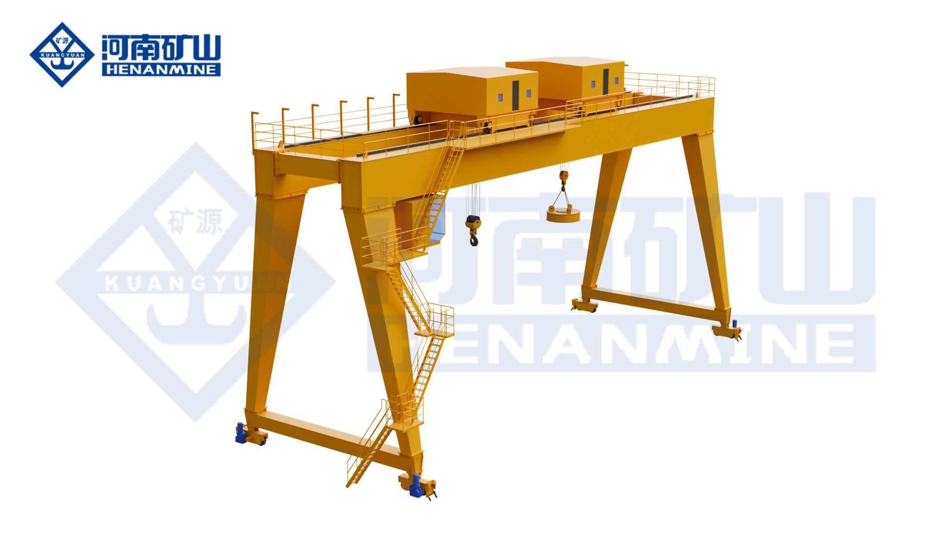
MEN double-trolley gantry crane with two lifting positions
MEN series

Double Trolley Magnet and Hook Gantry Crane (MEN)

Double-trolley magnetic and hook handling for defined steel-transfer tasks.

Trolley arrangementDouble trolley
Handling modesMagnet and hook
Working-class optionsA3–A8, selected to duty
All specifications
Model specifications and configuration choices
ModelMEN
Trolley arrangementDouble trolley
Handling modesElectromagnetic and hook handling
Working-class rangeA3–A8; select the class for the operating cycle
Control platformPLC module integrated with the control station
Operator interfaceHMI touch-screen interface
Master controllerWLK master controller
Controller functionsDefined operating steps, zero-return and locking functions
Magnet actuationPickup and release through electrical current switching
Structural designMain-girder, leg and end-girder stress distribution optimised by finite-element analysis
Cantilever arrangementOne side, both sides or no cantilever, according to the selected layout
Rated lifting capacitySpecify complete suspended load for each hook and electromagnetic handling mode
SpanRail-centre span selected for the working area
Lifting heightHook and magnet working heights selected for pickup and stacking levels
Trolley coordinationPermitted independent and coordinated functions defined for the process
Magnet packageMagnet type, suspension, power circuit and required holding / release functions specified
Steel materialSpecify material form, dimensions and relevant operating temperature
Duty and handling rateSelected for the actual pickup, travel, release and return cycle
Motion speedsLifting and travel speeds selected for controlled material placement
Site electrical supplyVoltage, frequency, phases and crane / magnet power-feed interfaces specified
MN double-girder gantry crane with grab and hook arrangements
MN series

Grab and Hook Gantry Crane (MN)

Grab and hook changeover for bulk materials and general cargo.

Handling modesGrab and hook
ChangeoverQuick-connection arrangement
Duty basisDefined for each mode
All specifications
Model specifications and configuration choices
ModelMN
Handling modesGrab for bulk material; hook for general cargo
Changeover systemDedicated quick-connection arrangement for grab / hook exchange
Grab rope systemCoordinated opening / closing ropes and supporting ropes for a rope-operated grab
Hook modeConventional hook-lifting operation
Motion controlVariable-frequency control
Wheel manufactureCombined forging and rolling process
Transmission couplingCrowned gear coupling
Maintenance arrangementModular design with replaceable core components
Grab-mode suspended loadGrab self-weight plus carried material and connecting equipment
Hook-mode capacityComplete hook-lifted load including slings and attachments
SpanRail-centre span selected for the working area
Lifting heightPickup level, discharge height and attachment dimensions selected together
Grab volume and materialSelected from material density, particle size and required load per cycle
Grab actuationHydraulic or mechanical opening / closing selected with the attachment package
Grab cycleOpening / closing speed and full handling cycle confirmed for the selected configuration
Working dutyLoad spectrum and cycle defined separately for grab and hook modes
Changeover procedureConnection, parking and attachment-handling provisions agreed for the work area
Operator controlsMode selection and required rope / attachment control functions specified
Electrical supplyCrane and any separate attachment power / control interfaces specified

Metallurgical, Tunnel Muck and Construction Gantry Cranes

Heat exposure, shaft depth and construction handling require different lifting packages. Match the mechanism and attachment to the process and its site interfaces.

MGY double-girder metallurgical gantry crane arrangement
MGY series

Metallurgical Gantry Crane (MGY)

Dedicated ladle lifting and slag-pot maintenance for specified metallurgical processes.

ApplicationLadle or slag-pot handling
ProtectionHeat-protection arrangement
ControlsPLC and HMI
All specifications
Model specifications and configuration choices
ModelMGY
Crane structureMetallurgical double-girder gantry
Lifting attachmentGantry-hook attachment for the selected vessel
Application focusSteel-ladle lifting or slag-pot maintenance
Thermal protectionHeat protection for key main-girder and leg structures
Thermal exposureArrangement intended for radiant-heat exposure in metallurgical work
Control platformPLC module with HMI touch screen
Master controllerWLK controller with defined steps, zero-return and locking functions
Lifting controlStator-voltage regulation for lifting speed control
Travel controlVariable-frequency travel-speed control
Structural designKey load-bearing members optimised by finite-element analysis
Rated lifting capacityVessel, contents, lifting attachment and connecting equipment assessed together
SpanRail-centre span selected for the working area
Lifting heightWorking hook levels selected for vessel pickup, transfer and maintenance
Vessel interfaceGantry-hook geometry and engagement matched to the vessel lifting points
Process and dutyLoad spectrum, handling sequence, shifts and required operating modes specified
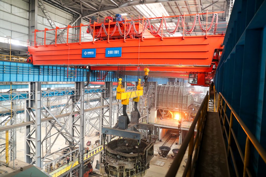
Heat conditionsVessel temperatures and radiant-heat exposure stated for the selected equipment
Lifting and travel speedsLoaded, positioning and travel speeds specified for the process
Electrical packageSite supply, protection and cable routing selected for the environment
Runway reactionsRail interface, wheel loads and relevant horizontal reactions provided for the selected crane
MGC double-girder gantry crane with a slag-handling bucket
MGC series

Tunnel Muck Handling Gantry Crane (MGC)

Lift, transfer and tip tunnel muck bins from shaft to discharge.

Handling taskTunnel muck and segments
SystemMatched bin and tipping gear
Lift requirementSelected with shaft depth
All specifications
Model specifications and configuration choices
ModelMGC
Application focusTunnel muck lifting, tipping and segment handling
Typical lifting capacityTypically 45–50 t; selected for the project and complete suspended load
Lifting-height capabilityUp to 100 m in project-specific arrangements; confirm with the selected load
Working dutyGenerally heavy-duty; exact working class selected for the cycle
Tipping systemDedicated spreader / tipping-hook arrangement with hydraulic tipping mechanism
Protection functionsOverload protection, travel limits, buffers and wind protection
Key transmission componentsForged wheels, crowned gear couplings and rolled steel-plate drums
SpanSelected for the shaft, discharge positions and site rail layout
Variable-span provisionVariable-span construction arrangement available where specified
Trolley rotation180° rotating trolley arrangement available for the discharge direction
Long-travel arrangementEight-wheel, four-drive arrangement specified with the selected crane
Wind restraintRail clamps and ground-anchor arrangement coordinated with the site
Muck-bin interfaceBin, lifting beam and tipping hooks selected as a matched system
Deep-lift rope systemHook travel, rope arrangement and hoisting package specified for the shaft depth
Discharge positionTipping envelope and discharge clearance shown in the layout
Segment handlingSegment load and lifting attachment specified where this duty is required
Operating controlsLifting, transfer, rotation and tipping functions defined for the selected equipment
Power and cablesSite supply and crane / trolley cable routes specified for the working area
Runway reactionsWheel loads, horizontal reactions and anchoring interfaces supplied for the selected arrangement
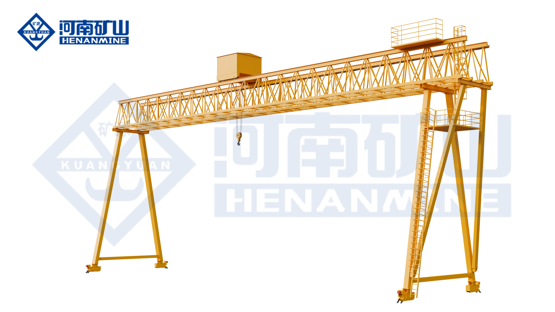
MGG truss-bridge construction gantry crane
MGG series

Construction Gantry Crane (MGG)

Twin-truss construction lifting for precast beams and site material transfer.

BridgeTwin truss girders
Lifting arrangementSingle trolley and winch
ApplicationBridge and highway work
All specifications
Model specifications and configuration choices
ModelMGG
Main-girder structureTwin truss main girders
Leg structureTubular steel legs
Trolley arrangementSingle trolley
Hoisting mechanismSingle winch
Application focusBridge and highway construction work
Handling tasksPrecast-beam lifting, material transfer and specified piling-spoil operations
Rated lifting capacitySelected for the complete suspended load, including lifting attachments and rigging
SpanRail-centre span selected for the construction work area
Lifting heightWorking hook travel selected for the construction lifting sequence
Working classSelected for the load spectrum, lifts per hour and shifts
Lifting attachmentHook, lifting beam or other attachment specified for the actual load
Hoisting speedLoaded lifting and positioning speeds selected with the winch package
Trolley travelCross-travel speed and usable hook approaches specified for the load route
Crane travelLong-travel speed and stopping control selected for the runway
Site clearancesLeg opening, load envelope and vehicle access shown in the arrangement
Transport and assemblyTransport sections, site assembly and installation access agreed
Operator controlsOperator position and control package selected for visibility
Electrical supplyVoltage, phases, frequency and power-feed route specified
Runway and exposureWheel reactions, rail interfaces and relevant wind provisions coordinated with the site

Double Girder Electric Hoist Gantry Cranes

Compare MHS and KSMHS at the load, useful hook height and working cycle you need. Review the hoist arrangement, trolley approaches, controls and service access.

MHS double-girder electric-hoist gantry crane
MHS series

Double Girder Electric Hoist Gantry Crane (MHS)

Electric-hoist double-girder lifting for yard loading and material transfer.

Rated capacity3–50 t
Span7.5–35 m
Lifting height4–30 m
All specifications
Model specifications and configuration choices
ModelMHS
Rated lifting capacity3–50 t
Span7.5–35 m
Lifting height4–30 m
Girder arrangementDouble girder
Runway/support layoutFull gantry; ground rails on both sides
Lifting mechanismElectric hoist
Hoist/trolley arrangementSeated electric-hoist trolley
Lifting attachmentHook
Working classA-class selected for the load spectrum and operating cycle
Lifting speedLifting and positioning speeds matched to the selected electric hoist
Trolley travel speedCross-travel speed and stopping control selected for the load route
Crane travel speedLong-travel speed selected for the runway and operating cycle
Travel driveMotor / gearbox / brake package matched to duty and wheel reactions
Operating controlsPendant / wireless remote / cabin options
Cantilever arrangementWith or without cantilever
Electrical supply380 V / 50 Hz; 220–660 V / 50–60 Hz supply options
Electrical protectionIP54 option; protected equipment scope defined in the electrical schedule
Runway rail profileRail section matched to wheel geometry, reactions and supporting structure
Motor ratingsLifting, trolley and crane-travel motor ratings specified in the equipment schedule
Operating patternIntermittent, repeated loading/unloading and material handling
Site layoutOverall height, leg clearance and hook approach shown in the crane drawing
KSMHS new-design double-girder electric-hoist gantry crane
KSMHS series

New-Design Double Girder Electric Hoist Gantry Crane (KSMHS)

Top-running electric-hoist lifting with variable-frequency motion control.

Working classA3–A5
Motion controlVariable frequency
Lifting arrangementTop-running hoist trolley
All specifications
Model specifications and configuration choices
ModelKSMHS
Rated lifting capacitySelected for the complete suspended load, including rigging
SpanRail-centre span selected for the working area
Lifting heightHook travel and headroom selected for pickup / set-down levels
Girder arrangementDouble girder
Runway/support layoutFull gantry; ground rails on both sides
Lifting mechanismElectric hoist
Hoist/trolley arrangementTop-running electric-hoist trolley
Lifting attachmentHook / grab / electromagnetic lifting configurations
Working classA3–A5
Lifting speedLifting and positioning speeds matched to the selected electric hoist
Trolley travel speedCross-travel speed and stopping control selected for the load route
Crane travel speedLong-travel speed selected for the runway and operating cycle
Travel drive / motion controlVariable-frequency lifting and travel
Operating controlsOperator control package selected for visibility and the lifting task
Cantilever arrangementWith or without cantilever
Electrical supplySite voltage, phases, frequency and power feed matched in the electrical package
Electrical connectorsHeavy-duty electrical plug connectors: IP55
Runway rail profileRail section matched to wheel geometry, reactions and supporting structure
Motor ratingsLifting, trolley and crane-travel motor ratings specified in the equipment schedule
Operating patternIntermittent, repeated loading/unloading and material handling
Speed adjustment ratio1:10

Double Trolley Truss Gantry Crane

For work needing two lifting positions on a truss bridge. Compare trolley spacing, handling modes and the transport sections and site joints required for installation.

MEH twin-trolley truss gantry crane
MEH series

Double Trolley Truss Gantry Crane (MEH)

Double-trolley truss lifting for loads with separated lifting points.

BridgeTruss arrangement
Lifting trolleysTwo
Working classA3–A5
All specifications
Model specifications and configuration choices
ModelMEH
StructureTruss gantry arrangement
Trolley arrangementDouble trolley
Working classA3–A5
Lifting controlVariable-frequency lifting-speed control
Travel controlVariable-frequency travel-speed control
Transport structureSegmented main and end-girder components
Site jointsBolted site assembly
Runway arrangementLegs on both sides; ground-level rail travel
Cantilever arrangementOne side, both sides or no cantilever, according to the selected layout
Rated lifting capacitySpecify each trolley load and the permitted shared lifting load
SpanSelected for the work-area coverage and transport-section design
Lifting heightSelected for pickup, stacking or equipment-installation levels
Trolley spacingUsable separation selected for lifting-point spacing
Handling modesIndependent and coordinated functions specified for the lifting task
Motion speedsLifting and travel speeds matched to positioning and cycle requirements
Transport envelopeSection dimensions and joint positions agreed for delivery access
Operator controlsControl package selected for the two-trolley arrangement
Electrical supplySite voltage, phases, frequency and crane power feed specified
Runway reactionsWheel loads and relevant horizontal reactions supplied for the selected crane

Double Girder Semi-Gantry Cranes

For a layout with one floor rail and one elevated runway. Compare hook, double-trolley and electric-hoist arrangements with the reactions and elevations of both supporting structures.

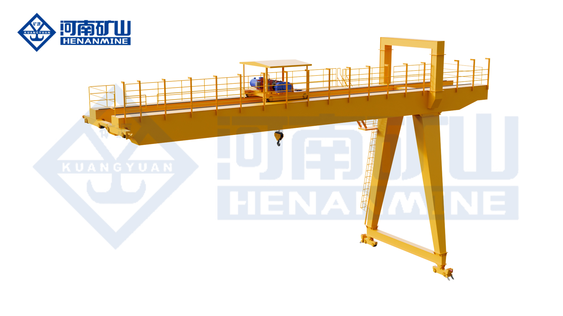
MGB hook semi-gantry arrangement
MGB series

Hook Semi-Gantry Crane (MGB)

Hook handling between one floor rail and one elevated runway.

Lifting attachmentHook
Support layoutFloor rail + elevated runway
Lifting packageSpecified in the offer
All specifications
Model specifications and configuration choices
ModelMGB
Crane arrangementHook semi-gantry developed from a double-girder gantry layout
Lifting attachmentHook
Floor-side supportLeg-supported ground-level rail
Elevated-side supportSuitable building structure or independent elevated support
Working motionsVertical lifting, trolley cross travel and crane long travel
Application focusWall-side workshop areas, storage edges and restricted working bays
Rated lifting capacitySelected for the complete suspended load, including lifting attachments and rigging
SpanHorizontal rail-centre distance selected for the working bay
Lifting heightUsable hook height selected with both runway elevations
Runway elevation differenceGround-side and elevated-side rail levels shown in the arrangement
Building-side reactionsVertical and horizontal runway reactions provided for support design
Ground-side foundationWheel loads and rail interface supplied for the floor-side support
Working classSelected for load spectrum, handling frequency and shifts
Lifting packageHoisting mechanism, hook block and speeds selected for the load
Cross-travel coverageHook approaches and work-area coverage checked against the elevated support
Travel and accessRunway length, stopping positions and clear floor route coordinated
Operator controlsOperator position and control package selected for the bay
Electrical supplySite voltage, frequency, phases and power-feed route specified
Installation scopeRunway supports, rail installation and crane assembly responsibilities agreed
MGBE twin-trolley semi-gantry crane
MGBE series

Double Trolley Semi-Gantry Crane (MGBE)

Two-trolley semi-gantry handling across floor-side and elevated runways.

Lifting trolleysTwo
Support layoutSemi-gantry
Motion controlVariable frequency
All specifications
Model specifications and configuration choices
ModelMGBE
Crane arrangementDouble-trolley semi-gantry
Trolley arrangementTwo lifting trolleys
Working-class rangeA3–A8; select the class for the operating cycle
Drive controlVariable-frequency motion control
Communication choices5G or industrial Ethernet communication for crane information synchronisation
Coordinated systemMulti-crane linked operation within a specified shared working area
Available attachmentsHook, grab or electromagnetic arrangements selected for the process
Rated lifting capacitySpecify trolley ratings and the permitted shared lifting load
SpanRail-centre span selected for the floor-side and elevated-side runways
Lifting heightWorking hook levels selected with both runway elevations
Lifting-point spacingTrolley separation selected for the load geometry
Permitted operating modesTrolley and multi-crane independent / joint functions specified in the control scope
Communication integrationNetwork coverage, interfaces and system responsibilities agreed for the site
Elevated-runway supportBuilding-side or independent support reactions supplied for the selected layout
Floor-side runwayRail interface, wheel loads and clear travel route coordinated
Motion speedsLifting and travel speeds selected for the coordinated process
Operator controlsOperator positions, visibility and control authority agreed for linked operation
Electrical supplyCrane and attachment supply and power-feed routes specified
Cantilever coverageAny required outside-span coverage confirmed in the selected arrangement
MB1 double-girder electric-hoist semi-gantry arrangement
MB1 series

Double Girder Electric Hoist Semi-Gantry Crane (MB1)

Electric-hoist double-girder handling beside a suitable elevated runway.

Lifting systemElectric hoist
Working classA3–A5
Support layoutSemi-gantry
All specifications
Model specifications and configuration choices
ModelMB₁
Rated lifting capacitySelected for the complete suspended load, including rigging
SpanRail-centre span selected for the working area
Lifting heightHook travel and headroom selected for pickup / set-down levels
Girder arrangementDouble girder
Runway/support layoutSemi-gantry; one elevated runway and one ground rail
Lifting mechanismElectric hoist
Hoist/trolley arrangementElectric-hoist trolley on twin girders
Lifting attachmentHook / grab / electromagnetic lifting configurations
Working classA3–A5
Lifting speedLifting and positioning speeds matched to the selected electric hoist
Trolley travel speedCross-travel speed and stopping control selected for the load route
Crane travel speedLong-travel speed selected for the runway and operating cycle
Travel drive / motion controlThree-in-one direct-connected crane and trolley travel drives
Operating controlsPendant / wireless remote; cabin or PLC-linked control by configuration
Cantilever arrangementWith or without cantilever
Electrical supplySite voltage, phases, frequency and power feed matched in the electrical package
Electrical protectionCabinet, motor and connector protection selected for the environment
Runway rail profileRail section matched to wheel geometry, reactions and supporting structure
Motor ratingsLifting, trolley and crane-travel motor ratings specified in the equipment schedule
Operating patternIntermittent, repeated loading/unloading and material handling
Site layoutOverall height, leg clearance and hook approach shown in the crane drawing
MBES new-design double-girder electric-hoist semi-gantry crane
MBES series

New-Design Double Girder Electric Hoist Semi-Gantry Crane (MBES)

Top-running electric-hoist semi-gantry lifting across two support elevations.

Hoist arrangementTop-running trolley
Working classA3–A5
Support layoutSemi-gantry
All specifications
Model specifications and configuration choices
ModelMBES
Rated lifting capacitySelected for the complete suspended load, including rigging
SpanRail-centre span selected for the working area
Lifting heightHook travel and headroom selected for pickup / set-down levels
Girder arrangementDouble girder
Runway/support layoutSemi-gantry; one elevated runway and one ground rail
Lifting mechanismElectric hoist
Hoist/trolley arrangementTop-running electric-hoist trolley
Lifting attachmentHook / grab / electromagnetic lifting configurations
Working classA3–A5
Lifting speedLifting and positioning speeds matched to the selected electric hoist
Trolley travel speedCross-travel speed and stopping control selected for the load route
Crane travel speedLong-travel speed selected for the runway and operating cycle
Travel drive / motion controlThree-in-one direct-connected crane and trolley travel drives
Operating controlsPendant / wireless remote options
Cantilever arrangementWith or without cantilever
Electrical supplySite voltage, phases, frequency and power feed matched in the electrical package
Electrical protectionCabinet, motor and connector protection selected for the environment
Runway rail profileRail section matched to wheel geometry, reactions and supporting structure
Motor ratingsLifting, trolley and crane-travel motor ratings specified in the equipment schedule
Operating patternIntermittent, repeated loading/unloading and material handling
Site layoutOverall height, leg clearance and hook approach shown in the crane drawing

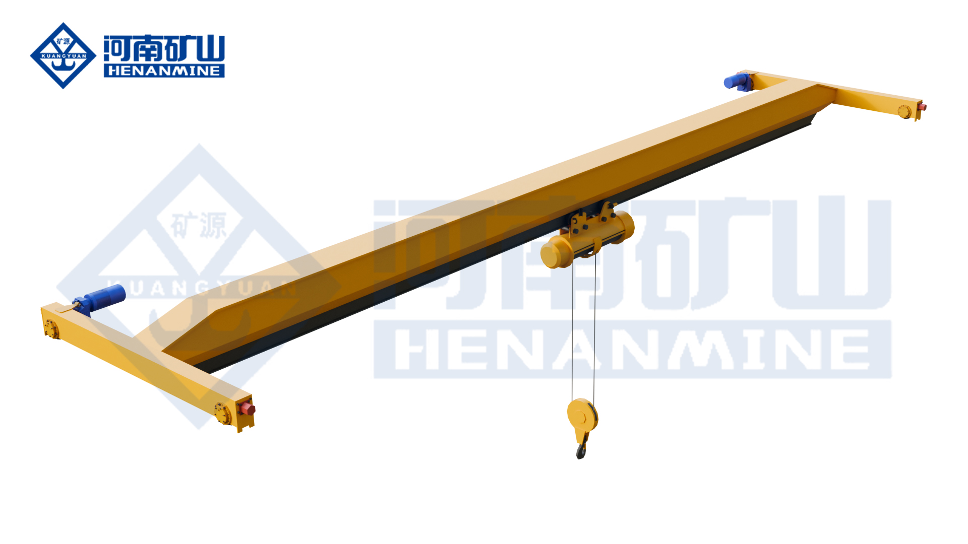
Two main girders describe the bridge, not the number of trolleys or the leg shape. A double-girder crane can use a single trolley, two trolleys or a specified electric-hoist arrangement. Compare the complete load, working cycle, useful opening and hook path for the selected configuration.

Check the Crane Against Your Working Space

A-frame or U-leg?

Compare the load and vehicle route at the heights and orientations used during handling. Leg geometry changes the available passage, hook approach and outside-span route. Confirm the useful opening on the proposed drawing.

Full gantry or semi-gantry?

A full gantry runs on two ground-level rails. A semi-gantry combines a floor rail with an elevated runway on suitable building support or an independent structure. Compare the clear aisle and reactions on both sides.

Box girder or truss?

Compare bridge geometry, wind conditions, wheel loads, transport sections and assembly access at the required load and span. A truss or segmented arrangement still needs its specified joints and service access.

A-Frame and U-Leg Reference Specifications

These four double-girder hook-gantry examples keep the load, span, lifting heights, motion speeds and runway information together. They are separate catalogue configurations, not guaranteed specifications for every MG or other model.

Scroll across to compare the complete configurations.

Matched hook-gantry reference configurations
SpecificationA-frame · 5 t / 22 mA-frame · 32/5 t / 22 mU-frame · 10 t / 22 mU-frame · 20/10 t / 26 m
Portal geometryA-frame · double girderA-frame · double girderU-frame · double girderU-frame · double girder
Main hook capacity5 t32 t10 t20 t
Auxiliary hook capacity—5 t—10 t
Span22 m22 m22 m26 m
Main lifting height10 m10 m11.5 m10.5 m
Auxiliary lifting height—10.73 m—11 m
Crane working classA5A5A5A5
Main hoisting speed11.3 m/min7.5 m/min8.5 m/min7.2 m/min
Auxiliary hoisting speed—15.4 m/min—10.4 m/min
Trolley travel speed37.3 m/min37 m/min43.8 m/min44.5 m/min
Crane travel speed37.3 m/min39.4 m/min37.6 m/min36 m/min
Maximum wheel load159 kN258 kN235 kN208 kN
Crane railP43P43 / QU70 · confirm selectionP4350 kg/m; QU70 · confirm specification
Motor power40.8 kW total99.3 kW totalHoist 17 kW; trolley 2 × 2.5 kW; crane 2 × 13 kWMain 26 kW; auxiliary 26 kW; trolley 2 × 4 kW; crane 4 × 8.5 kW
Supply voltage380 V380 V380 V380 V
Supply frequency50 Hz50 Hz50 Hz50 Hz
AC phases3-phase AC3-phase AC3-phase AC3-phase AC

Main and auxiliary capacities are separate hook ratings. Each column describes one arrangement; do not combine its values with another column. The 32/5 t A-frame rail choices come from a shared table and require confirmation. The 20/10 t U-frame rail notation also requires confirmation. U-frame motor figures are listed by mechanism, rather than as an inferred total. The selected drawing and wheel-load schedule define the order.

Budget planning

Double Girder Gantry Crane Prices

Compare budgets for the same rated hooks, span, lifting height and duty. These preliminary equipment allowances use the configurations below; the final quotation defines the crane, supply scope and delivery terms.

Preliminary double-girder gantry equipment budgets · USD
Main / auxiliary loadSpanLifting heightDutyBudget range (USD)
20/5 t28 m10 mA5USD 80,000–130,000
32/5 t26 m10 mA5USD 120,000–195,000
50/16 t39 m30 mA5USD 150,000–250,000

These rounded planning estimates are not current supplier quotations or confirmed transaction prices. Allow for the crane bridge and legs, selected hook trolley, end carriages and standard controls; runway rails, foundations, site power supply, freight, import charges, erection and commissioning are excluded unless stated in the offer. Main and auxiliary hook ratings remain separate and do not define a permitted combined lift.

The lifting package

A hook trolley, electric hoist, two-trolley system, grab or magnet changes the equipment. Match the selected mechanisms and duty to the actual load spectrum and handling cycle.

The working envelope

Compare the same rail-centre span, upper and lower hook positions, cantilever reach and load route. Different configurations cannot be reduced to a capacity-only price range.

Delivery and site work

Identify packing, freight terms, rail and power-feed scope, civil works, unloading, erection and commissioning. Compare exclusions as well as the quoted equipment price.

For an initial quotation, send the complete load, approximate span, useful lifting height and destination. Leave unknown dimensions open and describe the lifting task; a sketch or photo can help develop the proposal.

Get a configuration-based quotation
Select around the load and yard

Configure the Crane Around the Job

Main and auxiliary hooks

Specify each hook’s load, lifting height and speed, with its permitted operating modes. An auxiliary hook can serve a lighter task or a separate handling step; its rating is not automatically added to the main hook.

Double-trolley operation

Define the lifting-point spacing, load distribution and handling sequence. Agree whether trolleys operate independently, together or in both modes, with the shared-load limits and control functions stated.

Hoisting, travel and duty

Describe lifts per shift, load distribution and travel distances. Compare lifting and travel speeds, low-speed positioning, service access and working class for the selected mechanism.

Wind and outdoor exposure

State the installation location, wind, temperature and corrosion conditions. Agree working and parked provisions, wind monitoring and any selected rail clamps, brakes or anchoring interfaces.

Rails, foundations and clearance

Confirm rail centres, travel length, hook approaches, leg opening and cantilevers. Obtain wheel loads and horizontal reactions for the selected crane. Include both supporting elevations for a semi-gantry.

Power, controls and attachments

State the known voltage, frequency and phases, supply point and power-feed route. Select the operator position and attachment controls; define magnet holding/release and any backup requirements in the electrical package.

Compare the Equipment and the Work Included

The selected equipment

Enquire for one complete crane or a multi-crane project. Identify the structure, lifting mechanisms, hooks and attachments, control functions, power feed and any included rail equipment. State exclusions and the delivery term.

Documents and acceptance

Agree the general arrangement, equipment schedule, wheel-load information, electrical drawings and operating instructions. Identify destination requirements, inspection, functional checks and load testing for the equipment actually ordered.

Delivery and support

Request manufacturing and delivery timing for the agreed configuration. Allocate packing, freight, unloading, rail readiness, assembly, connections, commissioning and operator instruction. Record warranty terms, their starting point, spare-parts scope and service responsibilities in the offer.

Project applications

Double Girder Gantry Cranes in Project Lifting

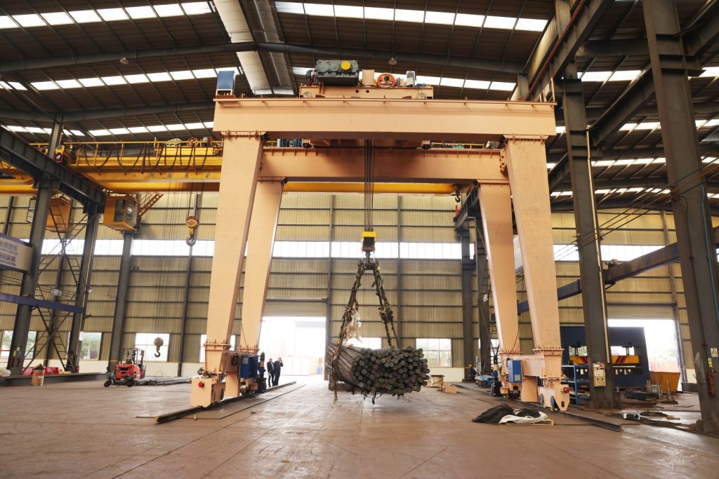
Factory acceptance · 100 t

100 t Double Girder Gantry Crane for a Nuclear Project

A 100 t double-girder gantry completed factory acceptance for a nuclear project, including heavy-load movement and positioning tests.

Where positioning is part of the lifting task, agree the load, motion sequence, control functions and acceptance checks together. This project image shows factory testing; it does not represent a customer-site installation.

View project details
100 t double-girder nuclear-project gantry carrying a suspended factory-test load
100 t nuclear-project gantry during factory testing.
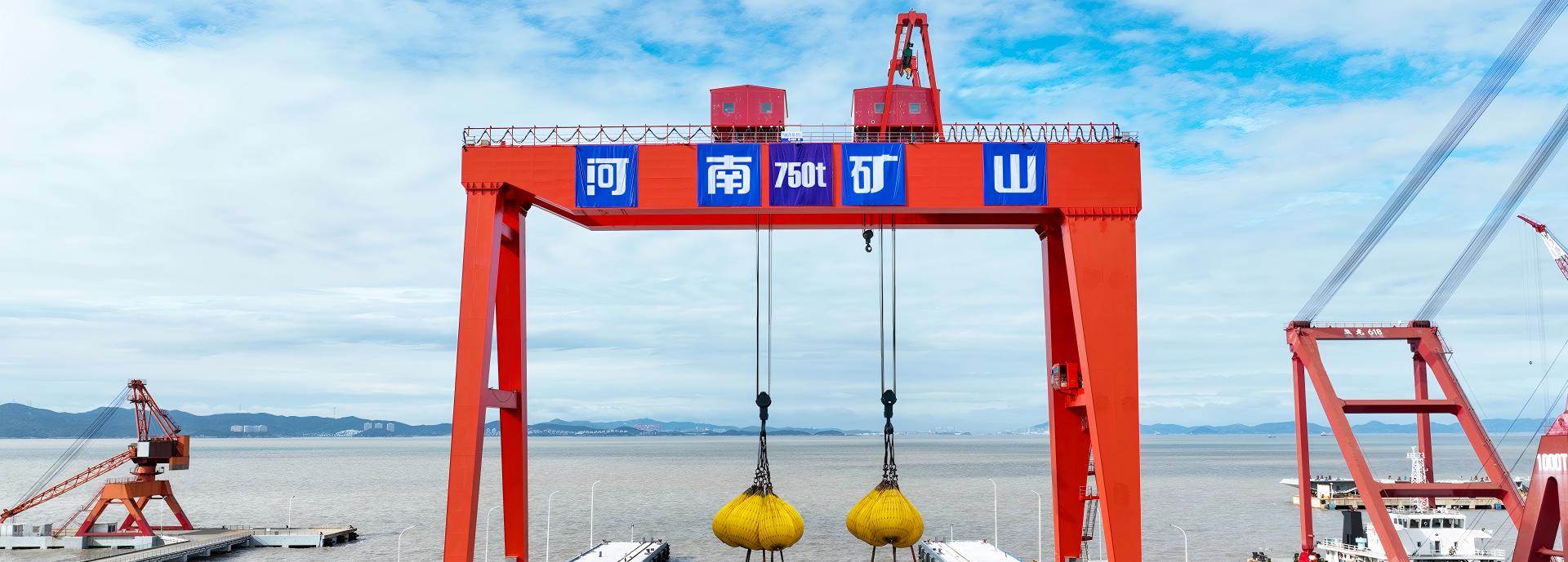
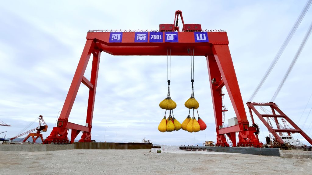
Zhejiang, China · 750 t

750 t Double Girder Gantry Crane in Zhejiang

This 750 t double-girder gantry entered use on a project in Zhejiang, China. The arrangement included coordinated lifting points and double rails on one side.

The project illustrates how a heavy-lift arrangement and its supporting runway are selected together. Its capacity and control functions are project-specific, rather than standard ratings for the models on this page.

View project details
750 t double-girder project gantry in Zhejiang with suspended test weights
750 t project gantry in Zhejiang, shown with suspended test weights.

Double Girder Gantry Crane Buying Questions

How should I compare single- and double-girder gantry cranes?

Use the same complete load, span, hook levels and working cycle for each proposal. Compare the offered mechanism, hook approaches, headroom, service access and runway reactions. The number of girders alone does not establish the capacity, duty or overall cost of the crane you need.

Are all double-girder gantries A-type cranes?

Double girder describes the bridge; A-type describes supporting-leg geometry. Compare the actual supporting layout and clear opening on the drawing, together with the hook path and any outside-span task. Different support arrangements can serve different material and vehicle routes.

Does a double-girder crane always have two lifting trolleys?

No. Two main girders can support a single lifting trolley or a selected double-trolley system. Main and auxiliary hooks on one trolley are also different from two separately travelling trolleys. Identify the lifting positions and operating sequence the workpiece needs before choosing the arrangement.

When should I compare an electric hoist with a winch trolley?

Compare both packages at the required load, useful hook travel and operating cycle. Review positioning speeds, trolley approaches, maintenance access and the controls offered with each mechanism. The selected equipment schedule should name the lifting package rather than leaving it implied by the gantry structure.

Can two trolley ratings or main and auxiliary hook ratings be added?

Use the operating limits stated for the complete crane. Individual ratings do not automatically define a permitted shared lift. Provide the lifting-point geometry, load distribution and any simultaneous or turning operation so the ratings, method and control functions can be selected together.

What should I check before selecting a semi-gantry?

Compare both rail elevations, the clear floor aisle and the reactions on the floor and elevated supports. An existing building-side runway needs suitable structural capacity; an independent elevated support is another layout option. Include vehicle crossings, hook approaches and site-work responsibility in the proposal.

Is a grab crane's stated rating the material payload?

Check the rating for the selected package. The complete suspended load includes the grab, carried material and connecting equipment. Material density, bucket volume, particle size and the full handling cycle affect the grab selection. Keep net-material payload separate from total suspended mass.

What needs to be specified for magnetic lifting?

Describe the steel form, dimensions, temperature and pickup arrangement. Include the magnet, suspension and connecting equipment in the complete load. Agree the power circuit, holding/release functions and any required backup provisions in the selected electrical package, with the operating and acceptance scope stated clearly.

Can a general hook gantry handle ladles or other hot process loads?

Choose equipment intended for the actual metallurgical duty. State the vessel, contents, lifting interface, heat exposure and handling sequence so the lifting system, controls and protection package address that process. Compare the dedicated metallurgical arrangement with the project requirements rather than relying on a general hook-crane capacity.

Can I combine any values shown in the specification tables?

Reference figures and options belong to their stated equipment or configuration. Request the load, span, lift and duty combination your task needs, then compare useful hook coverage, mechanisms and support reactions together. Main and auxiliary hook schedules remain separate unless a permitted operating mode is expressly defined.

What should be included when comparing quotations?

Compare the crane and lifting equipment with controls, attachments, power feed and any rail equipment included. Identify freight terms, civil work, assembly, commissioning and training responsibilities. Agree the documents, acceptance checks, delivery schedule, warranty terms and support scope for that same package.

Can I enquire before the layout and foundations are final?

Yes. Start with the load, approximate rail-centre span, useful lifting height and destination, leaving unknown items open. A short task description or optional sketch can explain the lifting points and route. The proposal can develop the selected arrangement and the support interfaces needed for the site design.

Compare the range

Double Girder Gantry Crane Specification Comparison

Shortlist by handling system and supporting layout. Open All specifications on each card for the complete model schedule, or select the full product name for its detail page.

Swipe across the table to compare models.

Product / modelHandling systemSupport layoutCapacity basisSpanLifting heightKey selection point
Double Girder Hook Gantry Crane (MG)Hook-handled cargo and componentsFull gantryProject-specificProject-specificProject-specificUsable hook coverage, clear leg opening and the complete operating cycle
Double Trolley Gantry Crane (ME)Two-trolley lifting; independent or joint operationFull gantryProject-specificProject-specificProject-specificTrolley spacing, shared-load limits and independent / joint operating modes
Grab Bucket Gantry Crane (MZ)Dedicated bulk-material grabFull gantry20 t reference package18–35 m, by configurationUp to 10 m, reference packageMaterial density, filled-grab mass and the complete handling cycle
Electromagnetic Gantry Crane (MC)Electromagnetic material handlingFull gantryProject-specificProject-specificProject-specificSteel form, total suspended weight and magnet power / release functions
Double Trolley Magnet and Hook Gantry Crane (MEN)Double-trolley magnet and hook dutiesFull gantryProject-specificProject-specificProject-specificMode-specific loads, trolley coordination and the electromagnetic control circuit
Grab and Hook Gantry Crane (MN)Quick-change grab and hook dutiesRail-mounted gantryProject-specificProject-specificProject-specificMode-specific suspended loads, rope functions and the attachment changeover
Metallurgical Gantry Crane (MGY)Metallurgical ladle / pot handlingFull gantryProject-specificProject-specificProject-specificVessel and lifting attachment, complete load and thermal exposure
Tunnel Muck Handling Gantry Crane (MGC)Muck-bin lifting, transfer and tippingConstruction-site full gantryTypically 45–50 t; project-specificProject-specificUp to 100 m; confirm selected arrangementShaft depth, bin interface, tipping direction and the selected capacity / lift combination
Construction Gantry Crane (MGG)Single-trolley construction liftingTwin-truss full gantryProject-specificProject-specificProject-specificSingle-trolley load path, site clearance and the construction lifting sequence
Double Girder Electric Hoist Gantry Crane (MHS)Electric-hoist hook handlingFull gantry3–50 t7.5–35 m4–30 mUpper hook position, trolley approach and the selected duty
New-Design Double Girder Electric Hoist Gantry Crane (KSMHS)Electric-hoist lifting configurationsFull gantryProject-specificProject-specificProject-specificHoist configuration, positioning speeds and usable hook coverage
Double Trolley Truss Gantry Crane (MEH)Double-trolley liftingTruss full gantryProject-specificProject-specificProject-specificTrolley spacing, coordinated handling and bolted transport-section interfaces
Hook Semi-Gantry Crane (MGB)Hook-handled components and cargoOne floor rail + one elevated runwayProject-specificProject-specificProject-specificRunway elevation difference, building-side reactions and clear floor access
Double Trolley Semi-Gantry Crane (MGBE)Double-trolley semi-gantry handlingOne floor rail + one elevated runwayProject-specificProject-specificProject-specificTrolley / crane coordination, communication scope and elevated-runway reactions
Double Girder Electric Hoist Semi-Gantry Crane (MB1)Electric-hoist lifting configurationsOne floor rail + one elevated runwayProject-specificProject-specificProject-specificRunway elevations, building-side reactions and clear floor access
New-Design Double Girder Electric Hoist Semi-Gantry Crane (MBES)Electric-hoist lifting configurationsOne floor rail + one elevated runwayProject-specificProject-specificProject-specificHook height, trolley approach and the two supporting runways

Listed options and reference figures do not establish every possible combination. Select the load, span, lifting height and duty together. The quotation, approved drawing and equipment schedule define the mechanisms, operating modes and support reactions for your crane.

Specialist Gantry Crane Applications

For classified areas, container handling or shipbuilding, compare the dedicated equipment family and its application-specific systems.

Explosion-Proof Gantry Cranes

Start with the hazardous-area classification, material and complete lifting task. Agree the protected mechanisms, controls and required equipment documents for that environment.

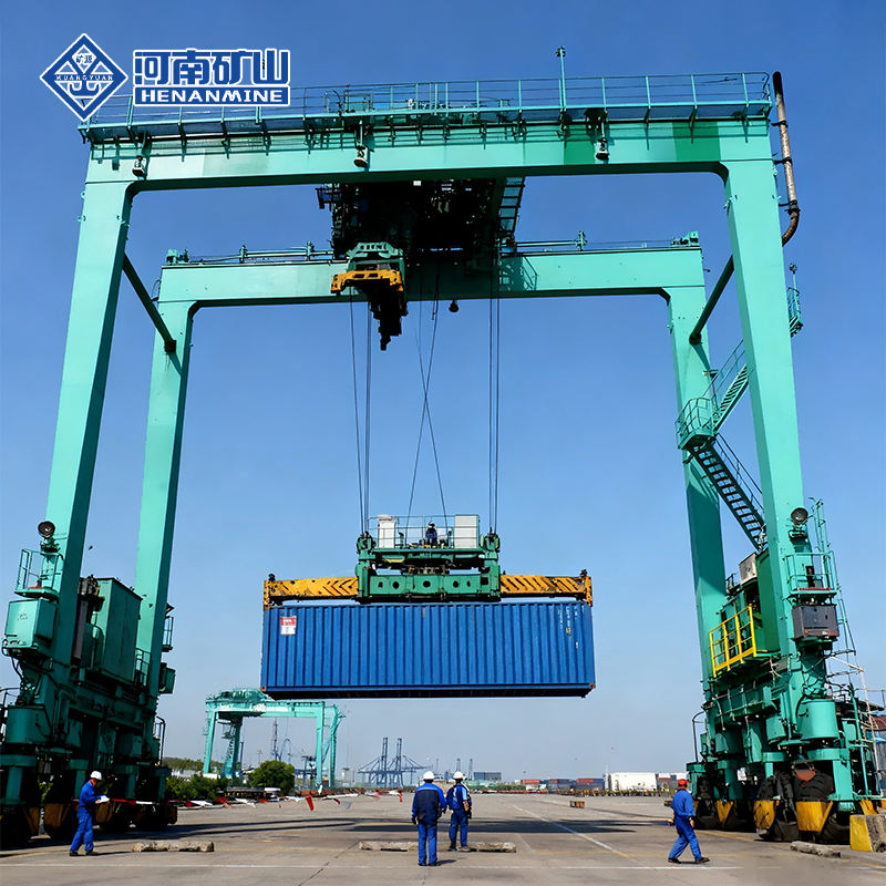
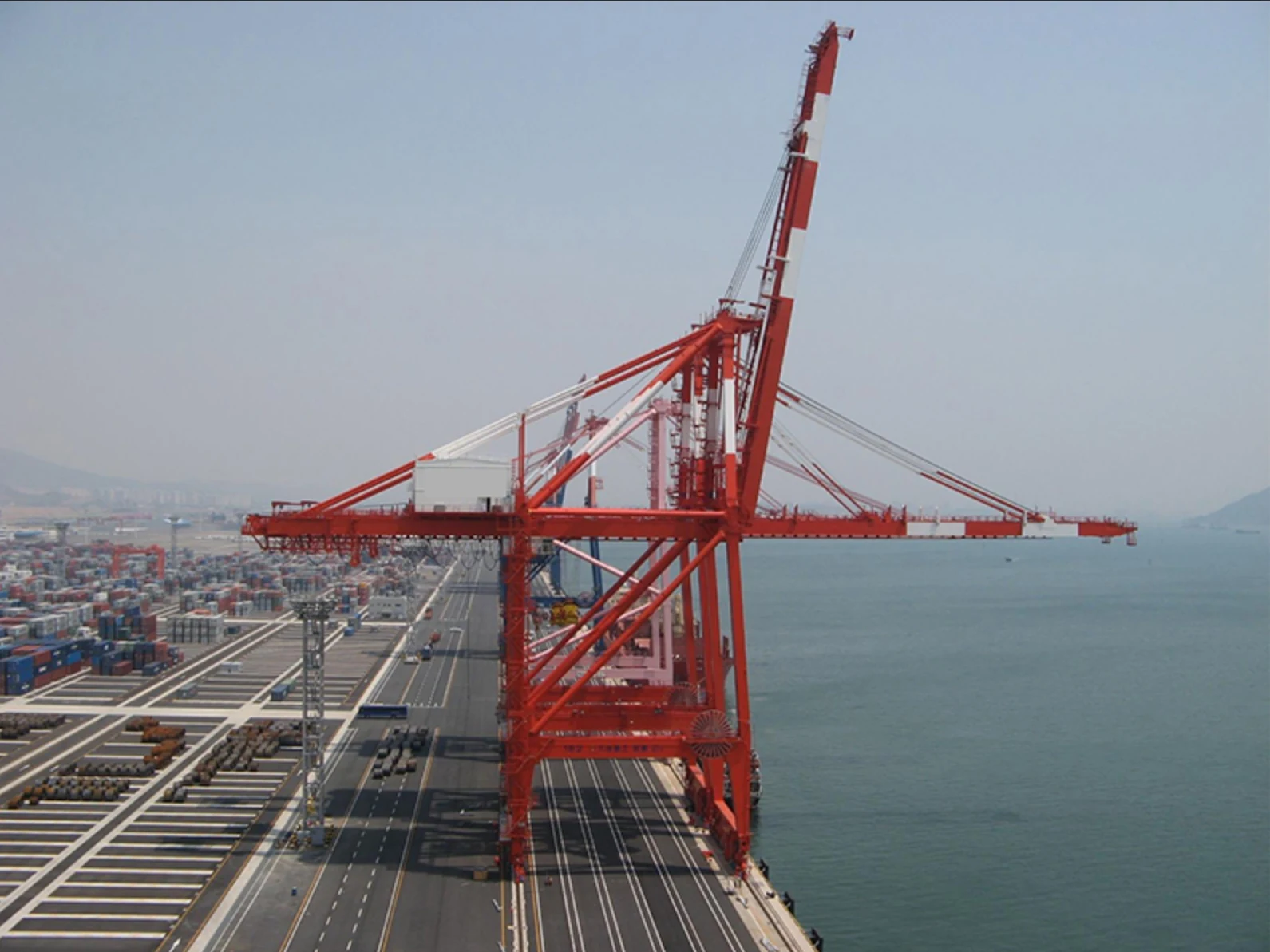
Rail-Mounted Container Gantry Cranes

Match the container spreader, stacking envelope, yard layout and handling cycle. Compare the dedicated container-crane family for terminal work.

Shipbuilding Gantry Cranes

For large block assembly and planned turning operations, compare the lifting arrangement, trolley positions and handling sequence around the shipyard project.

Request a Double Girder Gantry Crane Quotation

Send the complete load, approximate span, useful lifting height and destination. Add a task description or site sketch if available. For a two-point or process lift, include the lifting points, attachment and expected cycle.

Unknown dimensions can remain open for the initial enquiry. The proposal can develop the selected arrangement, drawings, support interfaces and an itemized technical and commercial scope.

Request a quotation